Table of Contents
Advertisement
Quick Links
Advertisement
Chapters
Table of Contents

Related Manuals for Omron C200H-CT021


Summary of Contents for Omron C200H-CT021
- Page 1 C200H-CT021 High-speed Counter Unit Operation Manual Revised December 2000...
- Page 3 OMRON. No patent liability is assumed with respect to the use of the information contained herein. Moreover, because OMRON is con- stantly striving to improve its high-quality products, the information contained in this manual is subject to change without notice.
-
Page 5: Table Of Contents
TABLE OF CONTENTS PRECAUTIONS ........xiii Intended Audience . - Page 6 TABLE OF CONTENTS SECTION 5 DM Area Allocation ....... . DM Area Allocation in Simple Counter Mode .
- Page 7 TABLE OF CONTENTS SECTION 10 Using IORD and IOWR Instructions ....115 10-1 IORD and IOWR Instructions..........10-2 Control Codes of IORD and IOWR Instructions .
- Page 8 Please read this manual carefully and be sure you understand the information provided before attempting to install and operate the C200H-CT021 High-speed Counter Unit. Be sure to read the precautions in the next section.
-
Page 9: Precautions
PRECAUTIONS This section provides general precautions for using the Programmable Controller (PC) and the High-speed Counter Unit. The information contained in this section is important for the safe and reliable application of the PC and the High-speed Counter Unit. You must read this section and understand the information contained before attempting to set up or operate a PC system. -
Page 10: Intended Audience
It is extremely important that a PC and all PC Units be used for the specified purpose and under the specified conditions, especially in applications that can directly or indirectly affect human life. You must consult with your OMRON representative before applying a PC System to the abovementioned applica- tions. -
Page 11: Operating Environment Precautions
Operating Environment Precautions • The PC will turn OFF all outputs when its self-diagnosis function detects any error or when a severe failure alarm (FALS) instruction is executed. As a countermeasure for such errors, external safety measures must be provided to ensure safety in the system. •... - Page 12 Application Precautions • Setting DIP switches or rotary switches. • Connecting cables or wiring the system. • Connecting or disconnecting the connectors. Failure to abide by the following precautions could lead to faulty operation of ! C a u t i o n the PC or the system, or could damage the PC or PC Units.
- Page 13 Application Precautions • Resume operation only after transferring to the new CPU Unit the con- tents of the DM Area, HR Area, and other data required for resuming operation. Not doing so may result in an unexpected operation. • Do not pull on the cables or bend the cables beyond their natural limit. Doing either of these may break the cables.
-
Page 14: Features And System Configuration
SECTION 1 Features and System Configuration This section provides a list of features and a system configuration example. Features............System Configuration . -
Page 15: Features
Section 1-1 Features Features The C200H-CT021 High-speed Counter is a Special I/O Unit for the C200H, C200HS, C200HX, C200HG, and C200HE PCs. The High-speed Counter Unit has the following features. Two Built-in Counters The High-speed Counter Unit has two high-speed increment/decrement... -
Page 16: System Configuration
In the following example, the size of each product on the belt conveyor is mea- Sizes sured and improper-sized products are removed from the line using the sole- noid. C200H-OA221 C200H-CT021 AC Output Unit High-speed Counter Unit C200HX Solenoid: Through-beam... - Page 17 Section 1-2 System Configuration Number of Mounted Units The maximum number of High-speed Counter Units and other Special I/O Units that can be mounted to the C200HX, C200HG, or C200HE CPU Rack, Expansion I/O Rack, or Slave Rack is 16 and the maximum number of those mounted to any other PC is 10.
-
Page 18: Specifications And Components
SECTION 2 Specifications and Components This section provides the Unit’s basic specifications and describes its major components. Specifications ..........2-1-1 General Specifications . -
Page 19: Specifications
Section 2-1 Specifications Specifications 2-1-1 General Specifications The general specifications conform to the C-series specifications. 2-1-2 Characteristics Item Specification Number of counters Operating modes Simple counter, linear counter, circular counter, preset counter, gate counter, cumulative gate counter, and sam- pling modes. Count Input signals Counter 1 inputs A and B and counter 2 inputs A and B... -
Page 20: I/O Electrical Specifications
Section 2-1 Specifications 2-1-3 I/O Electrical Specifications Input Characteristics Item Counter inputs A, B, and Z External control inputs IN1 and IN2 Input voltage 12 VDC ±10% 24 VDC ±10% RS-422 line driver 12 to 24 VDC ±10% Input current 14 mA (typical) at each voltage (12.9 to Conform to RS-422 line driver 4 to 11 mA 17.1 mA) - Page 21 Section 2-1 Specifications Output Characteristics Item External Outputs 0 to 7 Max. switching capacity 16 mA at 4.5 VDC to 80 mA at 26.4 VDC (See the following graph.) 320 mA max./common Leakage current 0.1 A max. Residual voltage 0.8 V max. ON/OFF response time 0.2 ms max.
-
Page 22: Counting Speed
The maximum response pulse frequency of the High-speed Counter for offset phase inputs is determined with the type of increment encoder connected to the High-speed Counter. In this following example, OMRON’s E6B-CWZ3C Encoder is connected to the High-speed Counter. Example:E6B-CWZ3C (500 pulses/time) -
Page 23: Bcd Or Hexadecimal Count Values
Section 2-1 Specifications The output offset phase is 90°±45°. Therefore, the greatest offset phase of the encoder is 45° (i.e., 90° – 45°). The Unit requires a minimum offset phase of 3.2 µs. Thus: 4.5 µs (When the rise and fall of the Encoder's 45°... -
Page 24: Dimensions
Section 2-1 Specifications Example: In the following example, the count value is FFFFFF. – {1000000 – (FFFFFF)} = – 1 = – 1 Hex. Hex. Hex. BCD In the following example, the count value is 800000. – {1000000 – (800000)} = – 800000 = – 8,388,608 Hex. -
Page 25: High-Speed Counter Unit Components
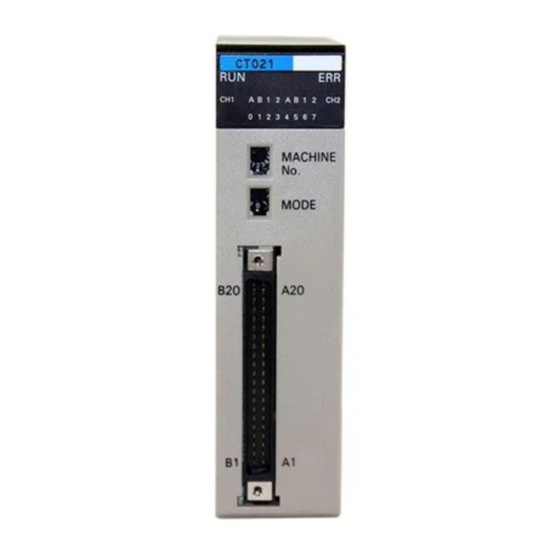
Section 2-2 High-speed Counter Unit Components High-speed Counter Unit Components 2-2-1 Nomenclature Indicators Rear setting switch Rotary switches Backplane connector External connector 2-2-2 Indicator Functions Indicator Name Function Operation Lit when the High-speed Counter is in normal counting operation. Not lit when the High-speed Counter stops counting pulses. -
Page 26: Switch Settings
Section 2-2 High-speed Counter Unit Components 2-2-3 Switch Settings There are two rotary switches on the front panel of the High-speed Counter Unit, which can be used for unit number and operating mode settings. Note 1. Be sure to turn OFF the High-speed Counter Unit before setting the unit number and operating mode. -
Page 27: Wiring
SECTION 3 Wiring This section explains how to connect various input and output devices to the High-speed Counter Unit. ! W A R N I N G Do not touch the terminals while the power is being supplied. Otherwise an electric shock may occur. External Connector Pins . -
Page 28: External Connector Pins
Section 3-1 External Connector Pins External Connector Pins The following table lists the allocation of the external connector pins on front side of the High-speed Counter Unit. Row B Pin no. Row A Counter 1 external control input IN2: Counter 2 external control input IN2: 12 or 24 VDC 12 or 24 VDC Counter 1 external control input IN1:... - Page 29 Section 3-2 Connector Wiring Method 2. Do not short-circuit any terminals when wiring. Covering each soldered portion with an insulating tube is recommended. 3. When using multi-conductor cables, separate the input and output cables. Wires Insulating tube Wire (Thickness: 0.3 mm max.) Connector Connector terminal side...
-
Page 30: I/O Circuit Configurations
Section 3-3 I/O Circuit Configurations Wiring Precautions Refer to the following for noise prevention when wiring counter inputs A, B, and Z. 1,2,3... 1. Use shielded, twisted-pair cable and ground the shield to a resistance of 100 Ω max. 2. Make the wiring as short as possible and do not run the wires parallel to lines that produce a lot of noise, such as high-power lines. - Page 31 Section 3-3 I/O Circuit Configurations Line Driver Input Terminals numbers in parentheses are used with counter 2. Configuration Terminal number Name Counter 1 input Z: (+) Counter 1 input Z: (−) Counter 1 input B: (+) Counter 1 input B: (−) Counter 1 input A: (+) Counter 1 input A: (−) External Output Configuration...
-
Page 32: Wiring Examples Of Encoder Inputs
The following are wiring examples of an encoder with A, B, and Z-phase out- puts. Wiring Example 1: 12-VDC Open-collector Encoder 12-VDC 12 VDC Power power supply Encoder C200H-CT021 High-speed Counter Unit Shielded, twisted-pair cable Counter input A 24 V 12 V A phase Counter input B Encoder... - Page 33 Section 3-4 Wiring Examples of Encoder Inputs Wiring Example 3: 12-VDC Voltage-output (Source load) Encoder Encoder 12-VDC 12 VDC power supply C200H-CT021 High-speed Counter Unit Shielded, twisted-pair cable Counter input A 24 V 12 V A phase Counter input B...
-
Page 34: Wiring Example Of External Control Inputs
Wiring Example of External Control Inputs In order to prevent chatter at the input, use solid-state as much as possible. 12- to 24-VDC 12 to 24 VDC C200H-CT021 High-speed Counter Unit power supply External control input IN1 12 or 24 V... -
Page 35: Example Of External Output Wiring
Example of External Output Wiring In the following example, relays are connected to external outputs 0 to 3 and TTLs are connected to external outputs 4 to 7. C200H-CT021 High-speed Counter Unit 5 to 24 VDC Fuse (1 A) Power supply... -
Page 36: Functions And Operating Modes
SECTION 4 Functions and Operating Modes This section describes the High-speed Counter Unit functions and their operating modes. Operating Modes ..........DM and IR Bit Allocation . -
Page 37: Operating Modes
Section 4-1 Operating Modes Operating Modes The High-speed Counter Unit can operate in any of the following seven modes selected with the rotary switch on the front panel of the High-speed Counter Unit. The modes other than the simple counter modes are classified according to the function. -
Page 38: Dm And Ir Bit Allocation
Note Unit numbers 10 to 15 (A to F) are available only when the C200HX, C200HG, or C200HE PC is used with the C200H-CT021. IR Area A block of 10 words between IR 100 to IR 199 or IR 400 to IR 459 is allocated to the Special I/O Unit. - Page 39 Section 4-2 DM and IR Bit Allocation Data of 10 IR words and data from the Special I/O Unit are transferred at the time of the PC’s I/O refresh. Example: C200HX High-speed Counter Unit [DM] DM 1000 to 1099 Unit 0 DM 1100 to 1199 Unit 1 DM 1200 to 1299...
-
Page 40: Linear Mode
Section 4-3 Linear Mode Linear Mode A total of 16 ranges with upper and lower limits between –8,388,608 and 8,388,607 can be set in this mode and when the count value is within the ranges, the High-speed Counter Unit will turn an output ON. (800000 to FFFFFF) (000000 to 7FFFFF) Count value... - Page 41 Section 4-3 Linear Mode A range consists of lower and upper limits and output pattern, and uses five words. The lower limit uses two words, the upper limit uses two words, and the output pattern uses one word. Up to 16 ranges are available. Lower limit Range 0 Upper limit...
-
Page 42: Circular Mode
Section 4-4 Circular Mode Output Pattern External outputs 7 to 0 correspond to the rightmost 8 bits (07 to 00) for the output pattern. External outputs Internal outputs To output pins 0 to 7 of the external connector. Both internal and external outputs or only eight internal outputs can be speci- fied. -
Page 43: Configuration Of Range
Section 4-4 Circular Mode If the present counter value is 600, outputs 7, 6, and 5 will be turned ON because the present counter value is within ranges 1 and 2, in which case the OR of the outputs will be turned ON. If the present counter value is 4,500, outputs 3, 2, and 1 will be turned ON because the present counter value is within ranges 0 and 3. -
Page 44: Preset Mode
Section 4-5 Preset Mode Upper and Lower Limits Upper and lower limits can be within a range of 0 to the maximum count value and Output Pattern set. Outputs 7 to 0 correspond to the rightmost 8 bits (07 to 00) for the output pat- tern. -
Page 45: External Output Pattern
Section 4-5 Preset Mode Note An interval of 2 ms min. is required between the preset count values marked with asterisks in the above chart, otherwise no external output can be obtained normally. 4-5-1 External Output Pattern External outputs 0 to 3 are for counter 1 and external outputs 4 to 7 are for counter 2. - Page 46 Section 4-5 Preset Mode Example 1: OFF Count Value of External Output 1 Set value: 0 to 8,388,607 (0 to 8,388,606 for external output 0 (4)) Hexadecimal Set to 0. Set value: 000000 to 7FFFFF (0 to 7FFFFE for external output 0 (4)) There is no difference in configuration among count values for external out- puts 0, 2, 4, 5, and 6.
-
Page 47: Gate Mode
Section 4-6 Gate Mode Example: Counter Preset Value 0 Set value: 1 to 8,388,607 Hexadecimal Set to 0. Set value: 000001 to 7FFFFF A maximum of six counter preset values can be changed by transferring data from the PC, in which case data blocks A to E and T for turning the outputs ON and OFF must be preset. -
Page 48: Cumulative Gate Mode
Section 4-7 Cumulative Gate Mode Cumulative Gate Mode The High-speed Counter Unit in this mode counts the number of pulses within a range of –8388,608 to 8,388,607 while control input IN2 is turned ON to accumulate the count value. The count value is reset at the rising edge of control input IN1. An external control input or an IR bit can be used as the control input. -
Page 49: Input Types
Section 4-9 Input Types The High-speed Counter Unit resets the count value at the rising edge of con- trol input IN1 and starts counting the number of pulses for a preset sampling time. The High-speed Counter Unit in this mode does not have any external output. 4-8-1 Configuration of Sampling Time Note The configuration in sampling mode is briefly described below to explain the... - Page 50 Section 4-9 Input Types Offset Phase Inputs High-speed Counter Unit Encoder A phase Connect to Counter input A match direction of B phase operation. Counter input B (Reset input) Z phase Counter input Z Forward Reverse rotation rotation When the A phase is 90° in When the A phase is 90°...
- Page 51 Section 4-9 Input Types Up and Down Pulse Inputs Encoder or sensor for decrementing High-speed Counter Unit Down pulses Counter input A Up pulses Encoder or sensor for incrementing Counter input B Reset inputs, etc. Counter input Z Sensor or switch Up pulses Down pulses The High-speed Counter Unit counts up and down pulse inputs when the...
-
Page 52: Counter Reset Conditions
Section 4-10 Counter Reset Conditions 4-10 Counter Reset Conditions The count value can be reset with the internal Reset Bit, external control input IN1, and counter input Z. There are 12 counter reset modes as shown in the following table. Counter reset modes are set with bits 08 to 15 of words m+1 and m+2. -
Page 53: Data Processing With Pc
Input Counter reset condition and timing External control input IN1 Reset Reset Note 1. The width of a pulse of counter input Z and that of external control input IN1 must be 0.1 ms min. 2. When the High-speed Counter Unit in counter reset operation uses counter input Z or external control input IN1, the input repetition frequency of counter input Z or external control input IN1 must be 500 cps max. - Page 54 Section 4-11 Data Processing with PC Note When the High-speed Counter Unit is mounted to a Slave Rack, there may be a data transfer delay between the Master and the Slave. Refer to C200H PCs Operation Manual for details.
-
Page 55: Dm Area Allocation
SECTION 5 DM Area Allocation This section provides information on the DM and IR bit allocation in each mode. DM Area Allocation in Simple Counter Mode ..... . . DM Area Allocation in Linear and Circular Modes. -
Page 56: Dm Area Allocation In Simple Counter Mode
Section 5-1 DM Area Allocation in Simple Counter Mode DM Area Allocation in Simple Counter Mode The following explains DM and IR bit allocation in simple counter mode. DM Allocation Word Function 00 to 03 Operating mode (0: Simple counter mode) 04 to 07 Not used. - Page 57 Section 5-1 DM Area Allocation in Simple Counter Mode Word Flag Function (input) n+2, n+3 00 to 15 Present Counter 1 Value Sign Stored data range: −8,388,608 to 8,388,607 Hexadecimal Set to 0. Stored data range: 800000 to FFFFFF (−8,388,608 to −1) and 000000 to 7FFFFF (0 to 8,388,607) n+4, n+5 00 to 15 Present Counter 2 Value Refer to the information on the above present counter 1 value.
-
Page 58: Dm Area Allocation In Linear And Circular Modes
Section 5-2 DM Area Allocation in Linear and Circular Modes DM Area Allocation in Linear and Circular Modes The section explains DM and IR bit allocation in linear and circular modes. DM Allocation Word Function 00 to 03 Operating mode (1: Linear mode; 2: Circular mode) 04 to 07 Forced external output setting (0: Disabled;... - Page 59 Section 5-2 DM Area Allocation in Linear and Circular Modes Word Function 00 to 03 PC data area (0: DM; 1: I/O; 2: LR; 3: HR; 4:AR; 5: EM) 04 to 07 Not used. 08 to 15 Number of transfer data blocks (01 to 03) PC data area Number of transfer PC data area...
- Page 60 Section 5-2 DM Area Allocation in Linear and Circular Modes Word Function 00 to 15 Ranges assigned to counter 2 (1: Enabled; 0: Disabled) Bits 00 to 15 correspond to ranges 0 to 15. m+7, 00 to 15 Max. count value of counter 1 (in circular mode only) Set to 0.
- Page 61 Section 5-2 DM Area Allocation in Linear and Circular Modes Word Function m+19 00 to 15 Output pattern of range 0 (1: ON; 0: OFF) External outputs Internal outputs To output pins 0 to 7 of the output connector Set bits to 1 so that signals will be output from the bits when the count value is between the upper and lower limits.
- Page 62 Section 5-2 DM Area Allocation in Linear and Circular Modes IR Bit Allocation Word Flag Function (output) Start/Stop Command Unit starts counting at the rising edge of this bit. Unit stops counting at the falling edge of this bit. If the forced external output function is dis- abled at this time, the preset counter value and output pattern will be kept on hold.
- Page 63 Section 5-2 DM Area Allocation in Linear and Circular Modes Word Flag Function (input) n+2, 00 to 15 Present Counter 1 Value Sign Stored data range: −8,388,608 to 8,388,607 Hexadecimal Set to 0. Stored data range: 800000 to FFFFFF (−8,388,608 to −1) and 000000 to 7FFFFF (0 to 8,388,607) n+4, 00 to 15...
-
Page 64: Dm Area Allocation In Preset Mode
Section 5-3 DM Area Allocation in Preset Mode DM Area Allocation in Preset Mode The section explains DM and IR bit allocation in preset mode. DM Allocation Word Function 00 to 03 Operating mode (3: Preset mode) 04 to 07 Forced external output setting (0: Disabled;... - Page 65 Section 5-3 DM Area Allocation in Preset Mode Word Function 00 to 03 PC data area (0: DM; 1: I/O; 2: LR; 3: HR; 4:AR; 5: EM) 04 to 07 Not used. 08 to 15 Number of transfer data blocks (01 to 06) PC data area Number of transfer PC data area...
- Page 66 Section 5-3 DM Area Allocation in Preset Mode Word Function m+10, 00 to Counter OFF count value of external output 0 m+11 Range: 0 to 8,388,606 Hexadecimal Set to 0. Range: 000000 to 7FFFFE m+12, 00 to ON count value of external output 1 m+13 Range: 0 to 8,388,607 (000000 to 7FFFFF) m+14,...
- Page 67 Section 5-3 DM Area Allocation in Preset Mode Word Function m+50, 00 to 15 Counter preset value 0 m+51 Range: 1 to 8,388,607 Hexadecimal Set to 0. Range: 000001 to 7FFFFF m+52, 00 to 15 Counter preset value 1 m+53 m+54, 00 to 15 Counter preset value 2...
- Page 68 Section 5-3 DM Area Allocation in Preset Mode IR Bit Allocation Word Flag Function (output) START Counter 1 Unit starts counting at the rising edge of this bit with the counter pre- Command set data of word n+1 if this bit is set to 1. Unit stops counting when word n bit 04 is set to 1 or the count value reaches 0.
- Page 69 Section 5-3 DM Area Allocation in Preset Mode Word Flag Function (input) n+4, n+5 00 to 15 Present Counter 2 Value Refer to the information on the above present counter 1 value. 00 Counter Counting Set to 1 when the counter is counting. Input Z Indicates the status of input Z (1: H;...
-
Page 70: Dm Area Allocation In Gate, Cumulative Gate, And Sampling Modes
Section 5-4 DM Area Allocation in Gate, Cumulative Gate, and Sam- DM Area Allocation in Gate, Cumulative Gate, and Sampling Modes The section explains DM and IR bit allocation in gate, cumulative gate, and sampling modes. DM Allocation Word Function 00 to 03 Operating mode (4: Gate mode;... - Page 71 Section 5-4 DM Area Allocation in Gate, Cumulative Gate, and Sam- IR Bit Allocation Word Flag Function (output) Not used. SET TIME for Counter 1 (The sampling time of word n+1 will be set only in sampling mode.) Command The sampling time for n+1 word is set at the rising edge. The new sampling time will be valid after the counter completes count- ing if the new sampling time is set while the counter is counting.
- Page 72 Section 5-4 DM Area Allocation in Gate, Cumulative Gate, and Sam- Word Flag Function (input) n+2, n+3 00 to 15 Present Counter 1 Value Sign Stored data range: −8,388,608 to 8,388,607 Hexadecimal Set to 0. Stored data ranges: 800000 to FFFFFF (−8,388,608 to −1) and 000000 to 7FFFFF (0 to 8,388,607) n+4, n+5 00 to 15 Present Counter 2 Value...
-
Page 73: Guidance For Program Development
SECTION 6 Guidance for Program Development This section describes the steps required to operate the High-speed Counter Unit in each mode, the DM required for unit number settings, and IR bit allocation. Operating Steps ..........Unit Number Setting. -
Page 74: Operating Steps
Section 6-1 Operating Steps Operating Steps Take the following steps to operate the High-speed Counter Unit. 1,2,3... 1. Decide the unit number of the High-speed Counter Unit and set the MA- CHINE No. switch to that unit number. 2. Decide the operating mode and set the MODE switch to that operating mode. -
Page 75: Unit Number Setting
Section 6-2 Unit Number Setting Unit Number Setting The C200H and C200HS PCs can each use a maximum of 10 Special I/O Units and their unit numbers set within a range of 0 to 9. The C200HX, C200HG, and C200HE PCs can each use a maximum of 16 Special I/O Units, the unit numbers of which are set within ranges of 0 to 9 and A to F. -
Page 76: Program Development With Drum Function
SECTION 7 Program Development with Drum Function This section describes program development using the drum function in linear and circular modes. Performance Specifications of Drum Function ..... . . DM Area Settings and Functions . -
Page 77: Performance Specifications Of Drum Function
Section 7-1 Performance Specifications of Drum Function Performance Specifications of Drum Function Refer to the following for the performance specifications of the drum function. Item Specification Count input signal Offset phase input Counter input A (A phase of encoder) Counter input B (B phase of encoder) Up and down pulse input Counter input A (Down pulse input) Counter input B (Up pulse input) - Page 78 Section 7-2 DM Area Settings and Functions Operating Mode Set these bits so that the setting will correspond to the MODE switch setting. (Word m Bits 03 to 00) Operating mode (1: Linear mode; 2: Circular mode) Forced External Output Forced external outputs are enabled or disabled with these bit settings.
- Page 79 Section 7-2 DM Area Settings and Functions Range Enabled/Disabled (Word (m+5) or (m+6)) Each bit (0: Disabled 1: Enabled) These bits are used to enable or disable ranges 0 to 15. Bits 00 to 15 corre- spond to ranges 0 to 15. The settings will be valid when the High-speed Counter Unit is turned ON or restarted until new ranges are transferred to the High-speed Counter Unit.
-
Page 80: Ir Area Settings And Functions
Section 7-3 IR Area Settings and Functions If the range of upper and lower limits includes 0, the lower limit will be larger than the upper limit in circular mode. Refer to the following example. Example: Upper and lower limit ranges in circular mode Range N Range M Lower limit... - Page 81 Section 7-3 IR Area Settings and Functions External Output Enabled External outputs 0 to 7 will be enabled and the corresponding indicators will (Word n Bit 07) be lit if this bit is set to 1. Data is transferred to word n+9 regardless of the set- ting of this bit.
- Page 82 Section 7-3 IR Area Settings and Functions Preset Counter Value These words are used to store the present counter values of the counters. (Words (n+2) and (n+3) Words (n+4) and (n+5)) Sign Sign The above is a setting example in BCD. The following data is stored.
-
Page 83: I/O Signal Timing Chart
Section 7-4 I/O Signal Timing Chart Output Status These bits indicate the status of outputs. (Word n+9) These bits are set to 1 regardless of the setting of word n bit 07 for the exter- nal output enabled function. External outputs Internal outputs I/O Signal Timing Chart Refer to the following for the relationship between input and output bits in lin-... -
Page 84: Data Transfer Programs
Section 7-5 Data Transfer Programs Data Transfer Programs The High-speed Counter Unit usually operates according to a maximum of 16 ranges set in the DM area. New ranges can be, however, transferred from the PC so that the High-speed Counter Unit can use new ranges. Note After writing a program, make sure that the program works properly. -
Page 85: Transfer Data Format (Ir And Dm Areas Of Pc)
Section 7-5 Data Transfer Programs Note Execute data transfer when the counters are not operating, otherwise no cor- rect output pattern will be obtainable. 7-5-2 Transfer Data Format (IR and DM Areas of PC) Upper and Lower Limits N: The first word number of the area set with the PC Wd N Range: 00 to 15 Wd (N+1) -
Page 86: Program Example For Range Change
Section 7-5 Data Transfer Programs 7-5-3 Program Example for Range Change The range is changed with external data transfer switches in the following example. Wd 0 Unit No. 0 points Rotary encoder SW1 (00000): Start switch SW2 (00001): Data transfer switch 1,2,3... -
Page 87: Program Example For Present Counter Value Change
Section 7-5 Data Transfer Programs 3. Program 25315 MOV(21) (1 cycle ON) #0000 (SW2) (SW1) 00001 00000 Data transfer DIFU(13) 03000 switch 03000 10000 Data transfer 10003 instruction (Start/Stop) 10614 DIFU(13) 03001 (Data transfer completion) DIFD(14) 03002 03000 03003 03001 03002 03003 00000... - Page 88 Section 7-5 Data Transfer Programs 2. Present Counter Value Preset Data Wd 2 Code (Set with a program) Wd 3 Present counter value preset data (Set with the rotary switches) Sign Wd 4 3. Program 25315 MOV(21) (1 cycle ON) #0000 (SW2) (SW1)
-
Page 89: Program Example For Linear Mode
High-speed Counter Unit in linear mode. Note After writing a program, make sure that the program works properly. System Configuration Process Control for a Conveyor Belt C200H-OC224 C200H-CT021 Contact Output Unit High-speed Counter Unit Use an Encoder Conversion Adapter to... - Page 90 Section 7-6 Program Example for Linear Mode DM Settings Example:Counter 1 DM 1100 Linear mode, external NPN outputs, BCD data, DM 1101 offset phase pulse inputs x 1, reset mode 10 DM 1105 Enabled ranges: 0 to 3 DM 1115 Range 0 DM 1116 1000 to 1200 (in process station 1)
-
Page 91: Program Example For Circular Mode
This section explains a program example for a system using counter 1 of the High-speed Counter Unit in circular mode. Note After writing a program, make sure that the program works properly. System Configuration Cam Timer Control C200H-CT021 High-speed Counter Unit External outputs 1, 6, and 7 Use an Encoder Conversion... - Page 92 Section 7-7 Program Example for Circular Mode Operation The control timing of a device connected to the shaft drive of the motor is detected by the incremental encoder, and outputs are controlled according to the angle of rotation. Offset phase inputs multiplied by 4 are input to the encoder. BCD data is used in the system.
-
Page 93: Program Development With Preset Function
SECTION 8 Program Development with Preset Function This section describes program development using the preset function. Performance Specifications of Preset Function ..... . . DM Area Settings and Functions . -
Page 94: Performance Specifications Of Preset Function
Section 8-1 Performance Specifications of Preset Function Performance Specifications of Preset Function Refer to the following for the performance specifications of the preset function. Outputs 0 to 3 are for counter 1 and outputs 4 to 7 are for counter 2. Item Specification Count input... -
Page 95: Dm Area Settings And Functions
Section 8-2 DM Area Settings and Functions DM Area Settings and Functions Values can be written to the DM area with ladder programs or the Program- ming Console. m = 1000 + 100 x Unit No. (0 to 15) The values set in the DM area are transferred to the High-speed Counter Unit when the High-speed Counter Unit is turned ON or restarted. - Page 96 Section 8-2 DM Area Settings and Functions Counter Input Type Offset phase pulse inputs must be multiplied by 1, 2 or 4. (Word (m+1) or (m+2) Bits 03 to 00) Input types 0: x 1 1: x 2 Offset phase inputs 2: x 4 3: Up and down pulse inputs 4: Pulse and direction inputs...
-
Page 97: Ir Area Settings And Functions
Section 8-3 IR Area Settings and Functions Counter Preset Value A maximum of 20 counter preset values (i.e., counter preset values 0 to 19) can be set within a range of words from m+50 to m+89. Each counter preset value uses two words. Set any unused counter preset value to 0. Example: Counter preset value (BCD) Range: 1 to 8,388,607 The Unit cannot operate with... - Page 98 Section 8-3 IR Area Settings and Functions External Output Enabled Set this bit to 1 in this mode. (Word n Bit 07) External outputs 0 to 7 will be enabled and the corresponding indicators will be lit if this bit is set to 1. Data is transferred to word n+9 regardless of the set- ting of this bit.
- Page 99 Section 8-3 IR Area Settings and Functions Status Data The status of the High-speed Counter Unit is transferred to the PC. (Word n+6) Flag Function Counter 1 Counting Set to 1 when the counter is counting. Input Z Indicates the status of input Z. Indicates the status of control input IN1.
-
Page 100: I/O Signal Timing Chart
Section 8-4 I/O Signal Timing Chart I/O Signal Timing Chart Refer to the following for the relationship between input and output bits in pre- set mode. Normal Operation Values in parentheses are for counter 2. External outputs 0 to 3 are for counter 1 and external outputs 4 to 7 are for counter 2. -
Page 101: Data Transfer Programs
Section 8-5 Data Transfer Programs Special Operation Values in parentheses are for counter 2. Counter preset value Count value Start Word n bit 00 (01) Counting Word n+6 bit 00 (08) Reset Word n bit 04 (05) Internal output Word n+9 bit 00 to 07 External output (Output to external connector pins) -
Page 102: Data Transfer Steps
Section 8-5 Data Transfer Programs 8-5-1 Data Transfer Steps Take the following steps to transfer data. 1, 2, 3... 1. Set the data storage area of the source. Initial settings 2. Turn ON or restart the High-speed Counter Unit. After turning ON or restarting the High- 3. -
Page 103: Program Example For Preset Value Change
Section 8-5 Data Transfer Programs 8-5-2 Program Example for Preset Value Change A preset value is changed with external data transfer switches in the following example. Wd 0 Unit No. 0 points Rotary encoder SW1 (00000): Start switch SW2 (00001): Data transfer switch 1,2,3... - Page 104 Section 8-5 Data Transfer Programs 3. Program 25315 MOV (21) (1 cycle ON) #0000 (SW2) (SW1) 00001 00000 Data transfer DIFU (13) 03000 switch 03000 10000 Data transfer 10003 instruction (Start/Stop) 10614 DIFU (13) 03001 (Data transfer completion) DIFD (14) 03002 03000 03003 03001...
-
Page 105: Program Example For Preset Mode
Note After writing a program, make sure that the program works properly. System Configuration Cutting Cable at the Target Position C200H-CT021 High-speed Counter Unit Use an Encoder Conversion Adapter to connect line driver outputs from an encoder with open collector outputs. - Page 106 Section 8-6 Program Example for Preset Mode Example Settings Counter preset value Item Set value Count value Counter preset value 10,000 Motor operation (External output 0) Speed (high/low) High (External output 1) 500 ms Brake (External output 2) Cutter (External output 3) Switch Settings The unit number of the High-speed Counter Unit is set to 1 and the Unit will have NPN external outputs.
- Page 107 Section 8-6 Program Example for Preset Mode Program Example Reset switch 11004 Counter 1 reset and operation reset 25313 (Always ON) 11007 Enable external output Start switch MOV(21) #**** Start preset value number 11000 Start 11903 (External output 3) Cutter operation completion DIFD(14)03000 (falling edge) detected 03000...
-
Page 108: Program Development With Counting Function
SECTION 9 Program Development with Counting Function This section describes program development using the counting function in gate, cumulative gate, and sampling modes. Performance Specifications of Counting Function..... DM Area Settings and Functions . -
Page 109: Performance Specifications Of Counting Function
Section 9-1 Performance Specifications of Counting Function Performance Specifications of Counting Function Refer to the following for the performance specifications of the counting func- tion. Item Specification Count input Offset phase Counter input A (A phase of encoder) signal input Counter input B (B phase of encoder) Up and down Counter input A (Down pulse input) -
Page 110: Ir Area Settings And Functions
Section 9-3 IR Area Settings and Functions Data Type These bits are used to set the counter value in BCD or hexadecimal. (Word m Bits 15 to 12) Data Type (0: BCD; 1: Hexadecimal) Counter Input Type Offset phase pulse inputs must be multiplied by 1, 2 or 4. (Word (m+1) or (m+2) Bits 03 to 00) Input types... - Page 111 Section 9-3 IR Area Settings and Functions Counters 1 and 2 will be set to the same sampling time if word n bits 01 and 02 are set to 1. Internal Control IN1 These bits will be used as control input signals if internal control IN1 and IN2 (Word n Bits 08 or 10) are set in word m+1 bits 04 to 07 and word m+2 bits 04 to 07.
-
Page 112: I/O Signal Timing Chart
Section 9-4 I/O Signal Timing Chart Status Data The status of the High-speed Counter Unit is transferred to the PC. (Word n+6) Flag Function Counter 1 Counting Set to 1 when the counter is counting. Input Z Indicates the status of input Z. Control input IN1 Indicates the status of external control input IN1. - Page 113 Section 9-4 I/O Signal Timing Chart Cumulative Gate Mode Values in parentheses are for counter 2. External or internal control input IN1 Word n bit 08 (10) (3) (4) External or internal control input IN2 Word n bit 09 (11) Present counter value Word n+2 and n+3 (n+4 and n+5)
-
Page 114: Program Example For Gate Mode
This section explains a program example for a system using the High-speed Counter Unit in gate mode. Note After writing a program, make sure that the program works properly. System Configuration Measuring Product Dimensions C200H-CT021 High-speed Counter Unit C200HX External control input IN1 Incremental encoder for Encoder... - Page 115 Section 9-5 Program Example for Gate Mode Program Example 11600 (Counting) DIFD(14)03000 25313 (Always ON) CLC(41) 03000 Checks whether count value is ≥ lower limit SUBL(55) DM0000 DM0004 25504 (CY Flag) KEEP Outputs if dimensions are too small. 00000 11600 25313 (Always ON) CLC(41)
-
Page 116: Program Example For Cumulative Gate Mode
Counter Unit in cumulative gate mode. Note After writing a program, make sure that the program works properly. System Configuration Detecting Incorrectly Processed Products C200H-CT021 High-speed Counter Unit C200HX Use an Encoder Conversion Adapter to connect line driver outputs from an encoder with open collector outputs. - Page 117 Section 9-6 Program Example for Cumulative Gate Mode Switch Settings The unit number of the High-speed Counter Unit is set to 1. Wiring The A- and B-phase outputs of the incremental encoder are connected to counter 1 inputs A and B. Connect the outputs of the photoelectric sensor to external control input IN2.
-
Page 118: Program Example 1 For Sampling Mode
This section explains a program example for a system using the High-speed Counter Unit in sampling mode. Note After writing a program, make sure that the program works properly. System Configuration Weight Measurement C200H-CT021 High-speed Counter Unit C200HX External control input IN1 Product 1 Use an Encoder Conversion... -
Page 119: Program Example 2 For Sampling Mode
MOV(21) DM0001 Program Example 2 for Sampling Mode Note After writing a program, make sure that the program works properly. System Configuration Speed Measurement (Tachometer) C200H-CT021 High-speed Counter Unit C200HX Encoder input A Encoder Conversion Adapter Incremental encoder (Resolution: 200 pulses/revolution) - Page 120 Section 9-8 Program Example 2 for Sampling Mode The value in the parentheses is for counter 2. Encoder input Internal control input IN1 Word n bit 01 (10) Sampling Sampling Counting time time Word n+6 bit 00 (08) Present counter value Number of revolutions conversion value (DM 0004 and 0005)
- Page 121 Section 9-8 Program Example 2 for Sampling Mode Program Example (Always ON) 25313 MOV(21) #1000 Sets sampling time to 1,000 ms 11001 MOV(21) #0003 DM0000 Sets values "0000" and "0003" in DM 0000 and DM 0001. MOV(21) #0000 DM0001 MOV(21) #0010 DM0002 Sets values "0000"...
-
Page 122: Using Iord And Iowr Instructions
SECTION 10 Using IORD and IOWR Instructions The IORD and IOWR instructions are enabled with the C200HE, C200HG, or C200HX PCs. These instructions make it possible to read data from the DM area allocated to the High-speed Counter Unit when it is turned ON or restarted, change the present counter value, or change values set in the High-speed Counter Unit. -
Page 123: Iord And Iowr Instructions
Section 10-1 IORD and IOWR Instructions 10-1 IORD and IOWR Instructions This section explains the configurations of the IORD and IOWR instructions. 10-1-1 IORD Instruction (@)IORD C: Control code S: Source unit number and number of words D: Destination address C: Control Code Control code... -
Page 124: Iowr Instruction
Section 10-1 IORD and IOWR Instructions D: Destination Address Set a data area of the PC that stores the data read from the High-speed Counter Unit. Example: Set C to 0005, S to F005, and D to D0100 to read range 5 of Unit F from DM 0100 in linear or circular mode. - Page 125 Section 10-1 IORD and IOWR Instructions Example: Set C to 0005 and D to F005 to write range 5 of unit F in linear or circular mode. Control Code CCXX A total of 1 to 99 words can be specified. Specify the total number of words to which data is written.
-
Page 126: Control Codes Of Iord And Iowr Instructions
Section 10-2 Control Codes of IORD and IOWR Instructions 10-2 Control Codes of IORD and IOWR Instructions This section describes how the control codes of the IORD and IOWR instruc- tions are used in each mode. Simple Counter Mode OK: Possible NG: Not possible Set item IORD instruction control code... - Page 127 Section 10-2 Control Codes of IORD and IOWR Instructions Preset Mode OK: Possible NG: Not possible Set item IORD instruction control code IOWR instruction control code #00XX #CCXX #00XX #CCXX #FX00 XX = 0 to 19 XX = 0 to 99 XX = 0 to 19 XX = 0 to 99 Operating mode...
-
Page 128: Types Of Data Written With Iowr Instruction
Section 10-3 Types of Data Written with IOWR Instruction Gate, Cumulative Gate, OK: Possible and Sampling Modes NG: Not possible Set item IORD instruction control code IOWR instruction control code #00XX #CCXX #00XX #CCXX #FX00 XX = 0 to 99 XX = 0 to 99 Operating mode Counter 1 input... - Page 129 Section 10-3 Types of Data Written with IOWR Instruction Preset Mode Set item Data transfer IOWR instruction Operating mode Not available Not available Counter 1 input Not available Not available Counter 2 input Not available Not available First word number of block of words Not available Available storing data transferred...
-
Page 130: Program Examples With Iord Instruction
Section 10-4 Program Examples with IORD Instruction 10-4 Program Examples with IORD Instruction Note After writing programs, make sure that the programs work properly. Example 1: Unit 0 in Linear Mode In the following example, the data of ranges 0 and 1 is read from DM 0000. Start 10606 10607... -
Page 131: Program Examples With Iowr Instruction
Section 10-5 Program Examples with IOWR Instruction 10-5 Program Examples with IOWR Instruction Note After writing programs, make sure that the programs work properly. Example 1: Unit 0 in Linear Mode In the following example, the present counter value of counter 1 is changed. Start 10606 10607... - Page 132 Section 10-5 Program Examples with IOWR Instruction Example 3: Unit 0 in Linear Mode In the following example, all the data of ranges 0 to 15 is changed. Case 1:Data Transfer Completion Flag is used for data transfer completion Start 10606 10607 @IOWR...
-
Page 133: Flags Used For Iowr Instruction And Data Transfer
Section 10-6 Flags Used for IOWR Instruction and Data Transfer 10-6 Flags Used for IOWR Instruction and Data Transfer This section shows the timing of each flag turned ON or OFF while the IOWR instruction or data transfer is executed. The Busy Flag does not change immediately after the IOWR instruction or data transfer is executed. -
Page 134: Error Processing And Troubleshooting
SECTION 11 Error Processing and Troubleshooting This section provides information on error processing and troubleshooting procedures. 11-1 Error Processing ..........11-2 Errors Monitored with CPU . -
Page 135: Error Processing
Section 11-1 Error Processing 11-1 Error Processing Error Indicators and When an error has occurred, the ERR indicator on the front panel of the High- Outputs speed Counter Unit will be lit, the Error Flag (word n+6 bit 15) will be set to 1, and the error code will be output to n+7. - Page 136 Section 11-1 Error Processing Error Code: Error Location: Two rightmost DM digits are indicated. If the DM digits cannot be specified, FF will be indicated. Indicates an error code number. Error Type of error Meaning code DM setting error The upper and lower limit range or the sign used for the upper or lower limit is incorrect. The value is an invalid BCD value or 0.
-
Page 137: Errors Monitored With Cpu
Section 11-2 Errors Monitored with CPU IOWR instruction with the correct data and transfer the error clear com- mand “EC” by executing the data transfer or IOWR instruction. If an error has occurred when the IORD instruction is executed, transfer the error clear command “EC”... -
Page 138: Functions Of Special I/O Unit's Ar And Ir Bits
Section 11-2 Errors Monitored with CPU 11-2-2 Functions of Special I/O Unit’s AR and IR Bits Error Indication If the same unit number is allocated to more than one Special I/O Unit mounted to a PC or a Special I/O Unit is mounted to a PC has not been refreshed by the CPU, the corresponding bit of the CPU is turned ON. - Page 139 Section 11-2 Errors Monitored with CPU Restart Flag The following bits are used to restart Special I/O Units by turning the Special I/ O Units OFF, ON, and OFF. C200H or C200HS Function AR 0100 Restarts Unit 0. AR 0101 Restarts Unit 1.
-
Page 140: Comparison With C200H-Ct001-V1
Appendix A Comparison with C200H-CT001-V1 The C200H-CT021 High-speed Counter Unit has two-axis pulse input functions. These functions are not iden- tical with the pulse input functions of the C200H-CT001-V1 High-speed Counter Unit. Refer to the following table. Function C200H-CT021 C200H-CT001-V1... -
Page 141: Data Area Allocation
Appendix B Data Area Allocation Switch Settings Switch Setting MACHINE No. 0 to F MODE Simple counter mode Linear mode Circular mode Preset mode Gate mode Cumulative gate mode Sampling mode Simple Counter Mode DM Allocation (m = 1000 + 100 x Unit No.) Present counter value Operating mode 0: BCD;... - Page 142 Appendix B Data Area Allocation Word (Input) Counter 1 Counter 1 Counter 2 Counter 2 Counter 1 Error Not used. Not used. present present present present counting location value value value value Counter 1 [x16 [x16 [x16 [x16 Input Z Counter 1 Control input IN1...
- Page 143 Appendix B Data Area Allocation Linear and Circular Modes DM Allocation (m = 1000 + 100 x Unit No.) Counter values and External output Forced external output Operating mode ranges mode 0: NPN; 1: PNP 0: Disabled; 1: Linear; 2: Circular 0: BCD;...
- Page 144 Appendix B Data Area Allocation IR Bit Allocation (n = 100 + 10 x Unit No.) or Word (Output) (n = 400 + 10 x (Unit No. – 10) if Unit No. is A to F) Start/Stop Valid value range number Each bit Change ranges for counter 1 1: Enabled...
- Page 145 Appendix B Data Area Allocation Word (Input) Counter 1 Counter 1 Counter 2 Counter 2 Counter 1 Error Operating Output present present present present counting location range status value value value value number Each bit Counter 1 Each bit 1:ON, [x16 [x16 [x16...
- Page 146 Appendix B Data Area Allocation First word number of PC’s words storing transfer data Number of transfer data blocks (01 to 06) PC data area 0: DM, 1: I/O, 2: LR, 3: HR, 4: AR, 5: EM m+5 to m+9 Not used.
- Page 147 Appendix B Data Area Allocation m+38 External output 6 OFF count value [x16 [x16 [x16 [x16 m+39 External output 6 OFF count value 0 [0] [x16 [x16 m+40 External output 7 ON hold time (Unit: 1 s) FFFF: ON hold –1 –2 m+41 to m+49...
- Page 148 Appendix B Data Area Allocation Word (Input) Counter 1 Counter 1 Counter 2 Counter 2 Counter 1 Error Counter 1 Output present present present present counting location preset value status of value value value value number each bit Counter 1 1:ON, [x16 [x16...
- Page 149 Appendix B Data Area Allocation IR Bit Allocation (n = 100 + 10 x Unit No.) or Word (Output) (n = 400 + 10 x (Unit No. – 10) if Unit No. is A to F) Not used. Sampling time Unit: ms (0001 to 9999) Set time for counter 1 Set time for counter 2...
- Page 150 Appendix B Data Area Allocation Word (Input) Counter 1 Counter 1 Counter 2 Counter 2 Counter 1 Error Counter 1 Counter 2 present present present present counting location sampling sampling value value value value time time Counter 1 [x16 [x16 [x16 [x16 Input Z...
-
Page 151: Cdm Coding Sheet Unit Number
Appendix C DM Coding Sheet Unit Number : DM 0 0 to DM Linear and Circular Modes 15 ↔ 00 15 ↔ 00 15 ↔ 00 Function Function Function Lower limit Range Lower limit Range Operating mode, forced external output, external output, and counter Upper limit Upper limit... - Page 152 Appendix C DM Coding Sheet Unit Number : DM 0 0 to DM Preset Mode 15 ↔ 00 15 ↔ 00 15 ↔ 00 Function Function Function External output 4 OFF Counter preset value 3 Operating mode, count value forced external output, external output, and External output 5 ON Counter preset value...
-
Page 153: Using With Cs1-Series Pcs
Using with CS1-series PCs Differences in Memory Allocation Note the following differences in memory allocation when using the C200H-CT021 with a CS1-series PC. CIO Area and DM Area Allocation • The beginning word, n, of the words in the IR Area (CIO Area) allocated to the C200-CT021 changes from n = IR 100 (400 for unit numbers A or higher) + (unit number ×... - Page 154 Appendix D Using with CS1-series PCs Data Configuration CIO Area Allocation (Example: Linear/Circular Modes) n = 2000 + (unit number × 10) Contents Direction Start, Data Transfer, Instructions from CPU Unit counter reset, CPU Unit to High-speed Counter external output, etc. n + 1 n + 2 Counter present value, error...
- Page 155 Appendix D Using with CS1-series PCs Programming Changing Set Values and Starting Counter Operation Example: Linear/Circular Modes • With ON for SW1 or OFF for SW2 as the input condition, the Data Transfer Command Bit (word n, bit 03) in the words allocated from the CIO Area is turned ON using OUT or another instruction.
- Page 156 Appendix D Using with CS1-series PCs Transferring Data Using the IOWR Instruction • With the execution start bit as the input condition, the IOWR instruction is executed and the present value of counter 1 is transferred to the High-speed Counter Unit. •...
-
Page 157: Index
Index Numerics control mode DM area settings 1 indicator counting function 2 indicator counter input type DM area settings A–B counting function drum function A indicator preset function allocation counter preset values data area DM area settings switch settings preset function range circular mode preset mode... - Page 158 Index drum function DM area settings preset function I/O signal IOWR timing chart IR area settings destination address linear mode IORD program example destination unit number IOWR dimensions direction inputs Encoder Conversion Adapter ERR indicator allocation error codes circular mode errors cumulative gate mode indicators...
- Page 159 Index external output drum function input output status line driver input drum function preset function indicators present counter value input characteristics counting function input configuration preset counter value inputs drum function direction preset function offset phase preset function pulse read error up and down pulse counting function installation...
- Page 160 Index offset phase inputs range configuration operating counter preset value number circular mode IR area settings linear mode preset function preset mode operating mode sampling mode DM area settings lower limit counting function circular mode drum function linear mode preset function maximum count value operating procedure circular mode...
- Page 161 Index IOWR sampling mode source unit number unit numbers IORD setting Special I/O Unit errors Restart Flags up and down pulses input specifications counting function drum function wiring preset function 12-VDC voltage-output encoder start sink load IR area settings 24-VDC open-collector encoder drum function 5-VDC voltage-output encoder start/stop...
-
Page 162: Revision History
Revision History A manual revision code appears as a suffix to the catalog number on the front cover of the manual. Cat. No. W311-E1-2 Revision code The following table outlines the changes made to the manual during each revision. Page numbers refer to the previous version.
Need help?
Do you have a question about the C200H-CT021 and is the answer not in the manual?
Questions and answers