Table of Contents
Advertisement
New Product
Multifunction Counter/Tachometer
H7CX-@
-N
Ultra-compact Counter Provides More
Complete Functionality.
Basic Features
• Short body with depth of only 59 mm (for 12 to 24-VDC Models with Screw Terminals).
• Better readability with character height of 12 mm on 4-digit models and 10 mm
on 6-digit models.
• The present value display characters can be switched between red, green, and orange.
Safety and Reliability
• New set value limit and counter functions have been added.
Other Features
• Front Panel can be changed to white or light gray.
• New models with two tachometer inputs and two tachometer outputs have
*4
been added to the series.
*1.For 100 to 240-VAC Models with Screw Terminals: 78 mm, Models with Sockets: 63.7 mm
(case dimension).
*2.The H7CX-A11 and H7CX-R11 have only red characters.
*3.The Front Panel can be replaced with an optional Front Panel (except for Tachometer-only Models).
*4.Only one prescale value provided.
Features
Basic Features
Ultra Short Body
The body depth has been greatly reduced. Helps in making thinner control panels.
12 to 24-VDC Models with Screw Terminals: 59 mm
100 to 240-VAC Models with Screw Terminals: 78 mm*
Models with Sockets: 63.7 mm (case dimension)
* Power supply circuit and input circuits are isolated for safety and reliability.
New models
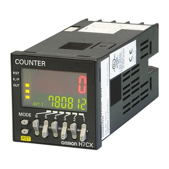
Easier to Read
For better readability, the character height for the present value
display is 12 mm on models with 4 digits, the largest class in the
industry. The wide viewing angle and brightness provide excellent
visibility. The number of display segments has also been increased to
make settings easier to understand, and the present value display
can be switched between red, green, and orange so that output status
can be seen from a distance.
Model with 4 Digits Model with 6 Digits
12 mm
10 mm
(actual size)
(actual size)
(Display example)
Note: The display color can be switched on all models except for the
H7CX-A11 and H7CX-R11.
The Easiest Operation
Operation is simplified by the
Model with 4 Digits
Up/Down Key for each digit
on 4-digit models and Up
Key for each digit on 6-digit
models.
*3
Previous
models
New
Previous
models
models
Easy to read from the top, bottom,
and sides!
Model with 6 Digits
*1
*2
For the most recent information on models that have been certified for
safety standards, refer to your OMRON website.
Refer to Safety Precautions on page 52.
Safety and Reliability
Isolated Power Supply and Input Circuits
Power supply circuit and input circuits are isolated inside the Counter/
Tachometer. Previous non-isolated counters had wiring restrictions
and could be damaged if wired incorrectly. The H7CX removes these
worries.
Note: Except 12 to 24-VDC models.
Set Value Limit
You can set an upper limit for the set value to prevent unexpected
operation of output devices caused by setting mistakes.
Setting the upper limit of the set
value enables worry-free operation.
No overflow
For 1,000 pieces
Output Counter
The output counter counts the number of times the output turns ON
(alarms can be displayed and the count can be monitored in
increments of 1,000 operations). This counter is useful in managing
the service life of the Counter/Tachometer or the load.
1
Advertisement
Table of Contents

Subscribe to Our Youtube Channel
Related Manuals for Omron H7CX- -N Series


Summary of Contents for Omron H7CX- -N Series
- Page 1 For the most recent information on models that have been certified for *1.For 100 to 240-VAC Models with Screw Terminals: 78 mm, Models with Sockets: 63.7 mm safety standards, refer to your OMRON website. (case dimension). *2.The H7CX-A11 and H7CX-R11 have only red characters.
-
Page 2: Other Features
H7CX-@-N Other Features Key Protection Select from any of seven protection patterns. Use the best one for the The front color can be changed simply by application. replacing the Front Panel. New Functions The Front Panel can be replaced with an optional Front Panel (sold separately) with a different color to match the installation site. -
Page 3: Model Number Legend
* The H7CX-R11W@ is a 1-stage (2 inputs and outputs) rather than a 2-stage Counter. Note: Estimates can be provided for coatings and other specifications that are not given in the datasheet. Ask your OMRON representative for details. Ordering Information... - Page 4 H7CX-@-N Accessories (Order Separately) Front Panels (Replacement Part) Model Color Applicable Counters Page Y92P-CXC4G Light gray (5Y7/1) 4-digit Counter Y92P-CXC4S White (5Y9.2/0.5) Y92P-CXC4B Black (N1.5) Y92P-CXC6G Light gray (5Y7/1) 6-digit Counter Y92P-CXC6S White (5Y9.2/0.5) Y92P-CXC6B Black (N1.5) Note: 1. You can change the color of the Front Panel when mounting the Counter. The Counter is shipped with a black (N1.5) Front Panel. 2.
-
Page 5: Specifications Ratings
*1. Not supported by the H7CX-A11@-N. *2. The functions that can be selected depend on the model. For the most recent information on models that have been certified for safety standards, refer to your OMRON website. Specifications Ratings Item... -
Page 6: Applicable Standards
Immunity Voltage Dip/Interruption: EN 61000-4-11: 0.5 cycle, 100% (rated voltage) * The following safety standards apply to models with sockets (H7CX-A11@ or H7CX-A114@). cUL (Listing): Applicable when an OMRON P2CF(-E) Socket is used. cUR (Recognition): Applicable when any other socket is used. - Page 7 H7CX-A@-N I/O Functions Using as a Counter (1) In general (except for Dual Counter Mode) • Reads counting signals. • Increment, decrement, command, individual, and quadrature inputs accepted. CP1, CP2 (2) When used as a dual counter or twin counter •...
- Page 8 H7CX-A@-N Connections Terminal Arrangement Confirm that the power supply meets specifications before use. H7CX-A-N/-A4-N H7CX-AD-N/-A4D-N H7CX-AS-N/-A4S-N 1-stage Contact Output 1-stage Contact Output 1-stage Transistor Output (−) (−) Sensor Sensor 12 VDC 12 VDC External External power supply power supply (−) Terminals 1 and 6 are connected internally.
-
Page 9: Block Diagram
H7CX-A@-N Block Diagram Input Circuits CP1, CP2, Reset/Reset 1, and Total Reset/Reset 2 (Basic insulation) Power supply Input Output circuit circuit (Basic insulation) (See note.) No-voltage Inputs Voltage Inputs (PNP Inputs) Display circuit (NPN Inputs) Internal Input circuits control circuit Key switch +14V circuit... - Page 10 H7CX-A@-N Nomenclature Display Section Operation Keys 1. Key Protect Indicator (orange) 10. Mode Key (Changes modes and setting items.) 2. Control Output Indicator (orange) 11. Reset Key (See note.) OUT: (One-stage) OUT: (Two-stage) 12. Up Keys 3. Reset Indicator (orange) (6-digit models: (Lit when the reset input (1) or Reset Key is ON.) Displayed only when the configuration selection...
- Page 11 H7CX-A@-N H7CX-AD-N/-ASD-N/-AWSD-N/-A4D-N/-A4SD-N/-A4WSD-N (Flush Mounting Models) 48 × 48 44.8 × 44.8 Note: M3.5 terminal screw (effective length: 6 mm) H7CX-A11-N/-A11S-N/-A11D1-N/-A11SD1-N/-A114-N/-A114S-N/-A114D1-N (Flush Mounting/Surface Mounting Models) 14.4 48 × 48 63.7 44.8 × 44.8 Dimensions with Flush Mounting Adapter H7CX-A-N/-AS-N/-AW-N/-AWS-N/-AWD1-N/-AWSD1-N/-A4-N/-A4S-N/-A4W-N Panel Cutouts Panel cutouts are as shown below.
- Page 12 H7CX-A@-N Accessories (Order Separately) Soft Cover Hard Cover Note: Depending on the operating environment, the condition Y92A-48F1 Y92A-48 of resin products may deteriorate, and may shrink or become harder. Therefore, it is recommended that resin products are replaced regularly. Front Panel (Replacement Part) You can change the color of the Front Panel when mounting the Protecting the Counter/Tachometer in Environments Counter/Tachometer.
- Page 13 H7CX-A@-N Connection Sockets Front Connecting Socket Terminal arrangement Mounting hole Model Dimensions and internal connections dimensions P2CF-11 31.2 max. 50 max. Two, 4.5-dia. holes 70 max. Two, M4 or 4.5-dia. holes Eleven, M3.5 × 7.5 sems screws ±0.2 P2CF-11-E 31.2 max. 50 max.
-
Page 14: End Plate
H7CX-A@-N Optional Products for Track Mounting Mounting Track ±0.15 PFP-100N PFP-50N ±0.3 ±0.15 15 (5)* 1,000 (500)* * The values shown in parentheses are for the PFP-50N. Mounting Track PFP-100N2 ±0.3 29.2 1,000 End Plate PFP-M M4 × 8 pan head screw 35.5 35.3 11.5... -
Page 15: Operating Procedures
H7CX-A@-N Counter Operating Procedures Setting Procedure Guide Setting for Counter Operation Use the following settings. Setting for Tachometer Operation Refer to page page 27. * At the time of delivery, the H7CX is set to the 1-stage preset counter configuration. (2-stage models are set to the 2-stage preset counter configuration.) Refer to page page 35 for information on switching models. - Page 16 H7CX-A@-N Counter Step3 Parameters that cannot be set with the DIP switch are set with the operation keys on the front panel. Change to Function Setting Mode. Power ON For details on operations and display in run mode, refer to page page 20. 3 s min.
- Page 17 H7CX-A@-N Counter To previous From previous page page Absolute value • Make the absolute value setting and forecast setting using the U (D) Keys. setting/forecast value setting (SETM) ofst (ABS) (OFST) Note: Displayed only when the configuration selection mode is set to the 2-stage function 2cnt. Set value •...
- Page 18 H7CX-A@-N Counter Explanation of Functions Items marked with stars ★ can be set using the DIP switch. Input Mode (cntm)★ Prescale Value (pscl) Set increment mode (UP), decrement mode (DOWN), or one of the Pulses input to the counter are converted according to the specified increment/decrement modes (UP/DOWN A, UP/DOWN B, or UP/ prescale value.
- Page 19 H7CX-A@-N Counter Absolute Value Setting/Forecast Value Setting (setm) Output ON Count Alarm Set Value (on-a) For the 2 count output mode, an absolute value setting (abs) or Set the alarm value for the output ON count. The limit can be set to between 0 × 1000 (0 times) and 9999 × 1000 forecast value setting (ofst) can be set for set value 1.
- Page 20 H7CX-A@-N Counter Operation in Run Mode I/O Functions for Counter Operation • Set values for each digit as required using the U Keys. (U Key only for 6-digit models.) 1-stage Preset Counter Total and Preset Counter Dual Counter Present value Set value Present value Dual count value...
- Page 21 H7CX-A@-N Counter Input Modes and Present Value (See note 1.) I/O Functions for Counter Operation UP (Increment) Mode DOWN (Decrement) Mode CP1: Count input; CP2: Prohibit (gate) input CP1: Count input; CP2: Prohibit (gate) input Prohibit Prohibit n−1 n−2 Present value Present value n−3 n−4...
- Page 22 H7CX-A@-N Counter Input/Output Mode Settings I/O Functions for Counter Operation If a 1-stage model or 2-stage model is incorrectly used as twin counter, the operation for One-shot output from OUT1 output 2 will be performed. When using a 2-stage model as a 1-stage preset counter, (The one-shot output time can be set in the range 0.01 to 99.99s.) total and preset counter, or dual counter, OUT1 and OUT2 turn ON and OFF...
- Page 23 H7CX-A@-N Counter One-shot output from OUT1 (The one-shot output time ca set in the range 0.01 to 99.9 Self-holding Self-holding One-shot output output output from OUT2 Input mode Operation after count completion DOWN UP/DOWN A, B, C The present value display does not Reset/ change during the...
- Page 24 H7CX-A@-N Counter (The one-shot output time can be set in the range 0.01 to 99.99s.) Self-holding Instantaneous One-shot output (equals) output output Input mode Operation after count completion UP/DOWN A, B, C Reset/ reset 1 999999 Set value 2 The display continues to increase/ Set value 1 decrease until the overflow or underflow value is reached.
- Page 25 H7CX-A@-N Counter Total and Preset Counter Operation The H7CX has a total counter, separate from the 1-stage preset counter, for counting the total accumulated value. • The total counter continues to count the total Reset/reset 1 accumulated value when the present value is reset using reset/reset 1 input (Reset Key).
- Page 26 H7CX-A@-N Counter Twin Counter Operation Two independent counters are built in. Counter 1 Counter 2 Counter input Reset input Reset 1 Reset 2 Counter 1 display Counter 2 display Counter 1 present value Counter 2 present value Present value display and setting Switched with Key.
- Page 27 H7CX-A@-N Tachometer Setting Procedure Guide Tachometer Operation Step1 The H7CX is factory-set to the 2-stage counter configuration (1-stage counter configuration for H7CX-AU@-N models). Enter configuration selection mode using the following chart and set the tachometer mode. Note: can be performed first, followed by Step2 Step1 Configuration...
- Page 28 H7CX-A@-N Tachometer Step3 Parameters that cannot be set with the DIP switch are set with the operation keys on the front panel. Change to Function Setting Mode. For details on operations and display in run mode, refer to page page 33. Power ON 3 s min.
- Page 29 H7CX-A@-N Tachometer To previous From previous page page NPN/PNP • Set the NPN/PNP input mode using the U Key. input mode (IMOD) (NPN input) (PNP input) Display • Set the display color using the U Key. color (COLR) (Red) (Green) (Orange) (Red-green) (Green-red) (Red-orange) (Orange-red) (Green-orange) (Orange-green) Peak/bottom •...
- Page 30 H7CX-A@-N Tachometer Explanation of Functions Tachometer Operation Items marked with stars ★ can be set using the DIP N: Number of pulses per revolution d: Diameter of rotating body (m) switch. d: Diameter πd: Circumference (m) Tachometer Input Mode (tinm) of rotating body (m) Set the count input mode to one of the following: 1 input (F1), 2 inputs...
- Page 31 H7CX-A@-N Tachometer NPN/PNP Input Mode (imod)★ Output Hysteresis (hys) Select either NPN input (no-voltage input) or PNP input (voltage This setting can be used to prevent output chattering if the input) as the input format. measurement value fluctuates slightly near the set value. When using a two-wire sensor, select NPN input.
- Page 32 H7CX-A@-N Tachometer ON Count Alarm Set Values for Outputs 1 and 2 (OUT1 and OUT2) (on1a and on2a) Set the ON count alarm values for the outputs 1 and 2. The limit can be set to between 0 × 1000 (0 times) and 9999 × 1000 (9,999,000 times).
-
Page 33: Operation In Run Mode
H7CX-A@-N Tachometer Operation in Run Mode Tachometer Operation • Set each digit using the individual U Keys. • Measurement value Measurement value Displays the currently measured value. • Comparison value 1/Comparison value 2 Set comparison value 1 and comparison value 2. Measurement value 1 The measurement value is compared to comparison value 1 and comparison value 2 and... - Page 34 H7CX-A@-N Output Mode Setting and Operation Tachometer Operation Input mode Output mode Operation setting setting (Upper-limit) Comparison value 2 Measurement value Upper and (Lower-limit) ON condition for OUT1: Measurement value ≤ Comparison value 1 Comparison value 1 lower limit ON condition for OUT2: Measurement value ≥ Comparison value 2 (HI-LO) OUT1 OUT2...
-
Page 35: Hold Function
H7CX-A@-N Switching between Preset Counter, Total and Preset Counter, Batch Counter, Dual Counter, Twin Counter, and Tachometer Operation Select which H7CX configuration is used (i.e., preset counter, total and preset counter, batch counter, dual counter, twin counter, or tachometer) in configuration selection mode. The H7CX is also equipped with a DIP switch monitor function, a convenient function that enables the settings of the DIP switch pins to be confirmed using the display on the front of the H7CX. -
Page 36: Self-Diagnostic Function
H7CX-A@-N Key Protect Level It is possible to prevent setting errors by prohibiting the use of certain operation keys by specifying the key protect level (KP-1 to KP-7) when the key-protect switch is set to ON. The key protect level is set in the function setting mode. The key protect indicator is lit when the key-protect switch is ON. (Disable) (Enable) *Factory-set to OFF... - Page 37 • Equipped with auto-zero time, average processing, and startup time functions. For the most recent information on models that have been certified for * The prescale value and auto-zero time settings are one. safety standards, refer to your OMRON website. Specifications Ratings Classification...
- Page 38 Immunity Voltage Dip/Interruption: EN61000-4-11: 0.5 cycle, 100% (rated voltage) * The following safety standards apply to the H7CX-R11@. cUL (Listing): Applicable when an OMRON P2CF(-E) Socket is used. cUR (Recognition): Applicable when any other socket is used. I/O Functions Count, count 1, Reads counting signals.
-
Page 39: Terminal Arrangement
H7CX-R@-N Connections Terminal Arrangement Block Diagram H7CX-R11-N (Basic insulation) Power supply H7CX-R11D1-N Output circuit circuit Hold (Basic insulation) (Basic insulation) Count Display circuit Hold Internal circuit Internal Input circuits Hold control circuit Key switch circuit (−) Sensor 12 VDC Input Circuits External power supply (−) - Page 40 H7CX-R@-N Input Connections The inputs of the H7CX-R are no-voltage (short-circuit or open) inputs or voltage inputs. They are set for use as voltage inputs at the time of delivery. No-voltage Inputs (NPN Inputs) Open Collector Voltage Output Contact Input DC Two-wire Sensor PLC or Sensor,...
- Page 41 H7CX-R@-N Nomenclature Display Section Operation Keys 1. Hold Indicator (orange) 7. Mode Key (Lit when the hold input or hold key is ON. ) (Used to switch mode and setting items.) 2. Key Protect Indicator (orange) 8. Hold Key Lit when the key protect switch is ON. (Used to sustain the measurement value and output.) 3.
-
Page 42: Connection Sockets
H7CX-R@-N Accessories (Order Separately) Flush Mounting Y92F-45 Adapter Note: Depending on the operating environment, the condition Use this Adapter to install the Y92F-30 of resin or rubber products may deteriorate, or they may Counter/Tachometer in a cutout shrink or become harder. Therefore, it is recommended Order a Flush Mounting Adapter previously made for a DIN 72 ×... - Page 43 H7CX-R@-N Operating Procedures Parameters must be set using both the DIP switch and the operation keys on the front panel. Refer to the following for the detailed procedure. Step1 Set the basic parameters. 1 2 3 4 5 6 7 8 (Factory setting) Counting speed/ Item...
- Page 44 H7CX-R@-N Step2 For details on operations in run mode, refer to page page 47. Change to Function Setting Mode. *1 If the mode is switched to the function setting mode during operation, operation will Power ON continue. *2 Changes made to settings in function setting mode are enabled for the first time when the mode is changed to run mode.
-
Page 45: Explanation Of Functions
H7CX-R@-N Explanation of Functions Advanced Functions Decimal Point Position (dp) Basic Functions Decide the decimal point position for the measurement value and Input Mode comparison value. The mode can be switched between tachometer mode and AMD- compatible mode. Prescale Value (pscl) Tachometer Mode It is possible to display the rate of rotation or the speed of a device or machine to which the H7CX is mounted by converting input pulses to... - Page 46 H7CX-R@-N Startup Time (stmr) Key Protect Level (ypt) In order to prevent undesired output resulting from unstable input Set the key protect level. immediately after the power supply is turned ON, measurement can Refer to Key Protect Level on page page 48. be prohibited for a set time at startup.
- Page 47 H7CX-R@-N Operation in Run Mode • Set each digit using the individual U Keys. H7CX-R11@-N Output Mode: HI-LO or AREA Output Mode: HI or LO • Measurement Value Measurement value Measurement value Displays the currently measured value. • Comparison Value, Comparison Value 1, and Comparison Value 2 Measurement value Measurement value...
- Page 48 H7CX-R@-N Key Protect Level When the key-protect switch is set to ON, it is possible to prevent setting errors by prohibiting the use of certain operation keys by specifying the key protect level (KP-1 to KP-7). The key protect level is set in the function setting mode. The key protect indicator is lit when the key-protect switch is ON.
- Page 49 H7CX-R@-N Output Mode Settings Models Other Than H7CX-R11W@ in Tachometer Mode Models Other Than H7CX-R11W@ in AMD-compatible Mode Output mode Output mode Operation Operation setting setting Comparison value 2 Comparison value 2 (Upper-limit) (Upper-limit) Measurement Measurement value value Comparison value 1 Upper and Upper and (Lower-limit)
- Page 50 H7CX-R@-N Precautions for the H7CX-R In upper and lower limit output mode, if the comparison value setting is such that comparison value 1 ≥ comparison value 2, the output will always be ON. Hold Function The measurement value (display value) and output are sustained while the hold input is ON. Note: The output will maintain the current status when the hold key is pressed.
-
Page 51: Setting Procedure
H7CX-R@-N Precautions on Replacing the AMD-S The H7CX-R11-N is the recommended model for replacing the AMD-S-series Motion Detector. Refer to the following precautions before replacing the AMD-S. Terminal Arrangement and Wiring Connections AMD-S H7CX-R11-N • Connection Sockets: P2CF-11 • Connection Sockets: 8PFA Black (white) Sensor HOLD... -
Page 52: Precautions For Safe Use
H7CX-@-N Safety Precautions for All H7CX Series (Common) • Internal elements may be destroyed if a voltage outside the rated CAUTION voltage range is applied. • Be sure that polarity is correct when wiring the terminals. Do not allow pieces of metal, wire clippings, or fine •... -
Page 53: Precautions For Correct Use
H7CX-@-N • Attach the front panel when using the Counter. The tabs in the Precautions for Correct Use middle of each of four sides secure the front panel to the main body. To remove the panel, widen the four tabs and pull the panel •... - Page 54 MEMO...
- Page 55 CONTRACT, WARRANTY, NEGLIGENCE, OR STRICT LIABILITY. In no event shall the responsibility of OMRON for any act exceed the individual price of the product on which liability is asserted. IN NO EVENT SHALL OMRON BE RESPONSIBLE FOR WARRANTY, REPAIR, OR OTHER CLAIMS REGARDING THE...
- Page 56 The Netherlands IL 60173-5302 U.S.A. Tel: (31)2356-81-300/Fax: (31)2356-81-388 Tel: (1) 847-843-7900/Fax: (1) 847-843-7787 © OMRON Corporation 2009 All Rights Reserved. OMRON (CHINA) CO., LTD. OMRON ASIA PACIFIC PTE. LTD. In the interest of product improvement, Room 2211, Bank of China Tower, No.
- Page 57 Counters & Tachometers Click to view products by manufacturer: Omron Other Similar products are found below : LC2H-FE-2K-N H7CN-XLN DC12-48 LC24-F-N H7CXAWD1NDC1224AC24 H7ER-NV1-H H7CX-A114S-N AC100-240 H7CX-AWSD- N-DC12-24 H7CX-AU-N AC100-240 GPMZC-SET CX6S-1P2F CX6S-1P4F CX6S-2P2F CX6S-2P4F H127.010A01H H5KLR-11 100- 240V AC/DC H7CX-AUD1-N H7CX-AW-N 3.550.401.075 3.550.401.351 LC2H-C-2K-N LC2H-C-30-N LC2H-F-DL-2KK LC4H-R4- AC240VS LC4H-R6-AC240V 1.150.510.012.550 1.150.510.054.550 1.150.510.056.550 6.520.012.300 6.560.010.300 SLE-73-1400-1-4-01...
Need help?
Do you have a question about the H7CX- -N Series and is the answer not in the manual?
Questions and answers