Omron SYSMAC CS Series Operation Manual
Customizable counter units
Hide thumbs
Also See for SYSMAC CS Series:
- Instruction & reference manual (1234 pages) ,
- Operation manual (841 pages) ,
- Programming manual (303 pages)

Related Manuals for Omron SYSMAC CS Series


Summary of Contents for Omron SYSMAC CS Series
- Page 1 Cat. No. W378-E1-02 SYSMAC CS Series CS1W-HIO01-V1/HCP22-V1/HCA22-V1/HCA12-V1 Customizable Counter Units OPERATION MANUAL...
- Page 3 CS1W-HIO01-V1/HCP22-V1/HCA22-V1/ HCA12-V1 Customizable Counter Units Operation Manual Revised December 2003...
- Page 4 Buyer indemnifies Omron against all related costs or expenses. rights of another party. 10. Force Majeure. Omron shall not be liable for any delay or failure in delivery 16. Property; Confidentiality. Any intellectual property in the Products is the exclu-...
- Page 5 OMRON. No patent liability is assumed with respect to the use of the information contained herein. Moreover, because OMRON is con- stantly striving to improve its high-quality products, the information contained in this manual is subject to change without notice.
-
Page 7: Table Of Contents
TABLE OF CONTENTS PRECAUTIONS ........Intended Audience ............General Precautions . - Page 8 TABLE OF CONTENTS SECTION 6 I/O Memory........Overview .
- Page 9 About this Manual: This manual describes the installation and operation of the CS1W-HIO01-V1, CS1W-HCP22-V1, CS1W-HCA22-V1 and CS1W-HCA12-V1 Customizable Counter Units and includes the sections described below. The Customizable Counter Units provide both normal contact I/O with special I/O as ideal control capabilities for many applications. The Customizable Counter Units are classified as CS-series Special I/O Units.
- Page 10 !WARNING Failure to read and understand the information provided in this manual may result in per- sonal injury or death, damage to the product, or product failure. Please read each section in its entirety and be sure you understand the information provided in the section and related sections before attempting any of the procedures or operations given.
-
Page 11: Precautions
PRECAUTIONS This section provides general precautions for using the CS1W-HIO01-V1, CS1W-HCP22-V1, CS1W-HCA22-V1 and CS1W-HCA12-V1 Customizable Counter Units. The information contained in this section is important for the safe and reliable application of the Customizable Counter Units. You must read this section and understand the information contained before attempting to set up or operate a Customizable Counter Unit. -
Page 12: Intended Audience
It is extremely important that a PLC and all PLC Units be used for the speci- fied purpose and under the specified conditions, especially in applications that can directly or indirectly affect human life. You must consult with your OMRON representative before applying a PLC System to the above-mentioned appli- cations. -
Page 13: Operating Environment Precautions
Operating Environment Precautions • Emergency stop circuits, interlock circuits, limit circuits, and similar safety measures must be provided in external control circuits. • The PLC will turn OFF all outputs when its self-diagnosis function detects any error or when a severe failure alarm (FALS) instruction is executed. As a countermeasure for such errors, external safety measures must be provided to ensure safety in the system. -
Page 14: Application Precautions
Application Precautions !Caution The operating environment of the PLC System can have a large effect on the longevity and reliability of the system. Improper operating environments can lead to malfunction, failure, and other unforeseeable problems with the PLC System. Be sure that the operating environment is within the specified condi- tions at installation and remains within the specified conditions during the life of the system. - Page 15 Application Precautions • Install external breakers and take other safety measures against short-cir- cuiting in external wiring. Insufficient safety measures against short-cir- cuiting may result in burning. • Do not apply voltages to the Input Units in excess of the rated input volt- age.
-
Page 16: Data Backup
Data Backup • When replacing parts, be sure to confirm that the rating of a new part is correct. Not doing so may result in malfunction or burning. • Before touching a Unit, be sure to first touch a grounded metallic object in order to discharge any static build-up. -
Page 17: User Programming
Data Backup Backup time 10th day 5th day 1st day Ambient temperature 25°C 40°C 75°C Note The times give above assume that the capacitor is completely charged. Power must be supply to the Unit for at least 15 minutes to completely charge the capacitor. -
Page 18: Conformance To Ec Directives
Concepts EMC Directives OMRON devices that comply with EC Directives also conform to the related EMC standards so that they can be more easily built into other devices or machines. The actual products have been checked for conformity to EMC standards (see the following note). -
Page 19: Conformance To Ec Directives
Conformance to EC Directives Conformance to EC Directives The CS1W-HIO01-V1, CS1W-HCP22-V1, CS1W-HCA22-V1 and CS1W- HCA12-V1 Customizable Counter Units comply with EC Directives. To ensure that the machine or device in which the Customizable Counter Unit is used complies with EC directives, the Unit must be installed as follows: 1,2,3... - Page 20 Conformance to EC Directives...
-
Page 21: Features And System Configuration
SECTION 1 Features and System Configuration This section describes the features of the Customizable Counter Units and the devices required in an extended system configuration. Outline ............1-1-1 Outline . -
Page 22: Outline
Outline Section 1-1 Outline 1-1-1 Outline The Customizable Counter Units are CS-series Special I/O Units that can be programmed using a ladder program and provide both standard contact I/O and special I/O (including pulse inputs, pulse outputs, and analog outputs). (I/O support depends on the model of the Unit.) The I/O of a Customizable Counter Unit can be controlled by the ladder pro- gram in it without intervention from the program in the CPU Unit to achieve... - Page 23 Outline Section 1-1 control" and "simplified position/speed control", which have been pro- cessed separately by the dedicated unit or system in existing models. 1) High-speed input of analog signals from displacement sensors etc, which have been processed in the linear sensor controller in the exist- ing system, enables the ladder program processing.
- Page 24 Outline Section 1-1 High-speed input of analog signals from Control the servo by the high-speed analog displacement sensors etc. output Analog Output Unit Motion Control Unit CPU Unit Basic I/O Unit programs contact input Analog Analog output Position information discrimi- output Linear sensor (limit the torque)
-
Page 25: Features
Outline Section 1-1 1-1-2 Features Programmable I/O Control • The program capacity for the ladder program in the Customizable Counter Unit is 4 Kwords. • Standard features include 12 contact inputs and 8 contact outputs. • For special I/O, the CS1W-HCP22-V1 provides 2 pulse inputs and 2 pulse outputs, while the CS1W-HCA22-V1 provides 2 pulse inputs and 2 analog outputs. - Page 26 HCA22-V1/HCA12-V1) With this input, it is possible to take in the absolute encoder output data directly from the servo drivers manufactured by OMRON, etc. Since it enables the feedback input of the absolute value information, the analog output mentioned above can be used for position control.
-
Page 27: Application Examples
• Using this unit with a servo driver of an analog input type and a pres- sure sensor enables the control as described below. Note that the ser- vo driver (W series manufactured by OMRON in the example) is to be in the "speed control" mode. - Page 28 Outline Section 1-1 • System configuration Customizable Counter Unit CS1W-HCA12-V1 CS-series CPU Unit Analog output (−10 to +10 V): ON/OFF Speed control Analog input Analog output (0 to 10 V): (4 to 20 mA) Torque limit) Position detector Signal from absolute encoder Pressure Servo driver...
- Page 29 Outline Section 1-1 Customizable Counter Unit Servo driver (Omron W-series) CS1W-HCA12-V1 Control mode: Speed control (analog commands) Analog output Position control, (Speed control) switch Speed control −10 to 10 V, etc. (SPED or ACC instruction) Speed control SEN signal Signal from...
- Page 30 Outline Section 1-1 • System configuration Customizable Counter Unit CS1W-HCA12-V1 CS-series CPU Unit 4 to 20 mA ON/OFF Displacement Photo-electric Switches Sensor Moving at high speed • Operation Process 1) High-speed analog input (immediate refresh) 4 to 20 mA signals from the displacement sensor are input to and refreshed in the unit at every PRV instruction execution.
- Page 31 PC for analyses. b) The data can be transferred to the CPU unit's data memory by batch processing, and the line plot of the data can be displayed on the screen of the programmable terminal (NS series by OMRON).
- Page 32 Outline Section 1-1 • System configuration NS series PT Customizable Counter Unit CS1W-HCA12-V1 CS-series CPU Unit Memory card Personal computer Store the line plot Analyze 4 to 20 mA ON/OFF Injection Process Displacement Photo-electric Switches Sensor Moving at high speed...
- Page 33 Outline Section 1-1 • Operation Process 1) High-speed analog input by scheduled interrupts with the ladder program (immediate refresh) The PRV instruction is executed at each of constant executions of subroutine programs with the scheduled interrupts (interval timer). 4 to 20 mA signals from the displacement sensor are input, re- freshed, and stored (trace data) in the I/O memory area (Ex.
-
Page 34: Models And System Configurations
Models and System Configurations Section 1-2 Models and System Configurations 1-2-1 Models There are three models of Customizable Counter Unit, all of which are classi- fied as CS1 Special I/O Units. Model number Functions CS1W-HIO01-V1 12 contact inputs, 8 contact outputs CS1W-HCP22-V1 12 contact inputs, 8 contact outputs, 2 pulse inputs, 2 pulse out- puts CS1W-HCA22-V1 12 contact inputs, 8 contact outputs, 2 pulse inputs, 2 analog out-... - Page 35 Models and System Configurations Section 1-2 CS1W-HCP22-V1 (Pulse Inputs and Pulse Outputs) Programming Device CX-Programmer Creating, transferring, and monitoring the program for the Customizable Counter Unit. Programming Console Peripheral Port Connecting Cable (peripheral bus) CS1W-HCP22-V1 Customizable Counter Unit CS-series CPU Unit 12 contact inputs, 4 of which can be used as interrupt inputs...
- Page 36 Models and System Configurations Section 1-2 CS1W-HCA22-V1 (Pulse Inputs and Analog Outputs) CX-Programmer Programming Creating, transferring, and Device monitoring the program for the Customizable Counter Programming Unit. Console Peripheral Port Connecting Cable (peripheral bus) CS1W-HCA22-V1 Customizable Counter Unit CS-series CPU Unit 12 contact inputs, 4 of which can be used as interrupt inputs...
- Page 37 Customizable Counter Unit and can be purchased separately. The cables for these connectors must be provided and wired to the connec- tors by the user. An OMRON Connector–Terminal Block Conversion Unit can also be used for the special I/O. Refer to 3-3 Wiring for details.
- Page 38 Models and System Configurations Section 1-2...
-
Page 39: Specifications
SECTION 2 Specifications This section provides performance specifications and I/O specifications for the Customizable Counter Unit. Performance Specifications ........2-1-1 Available Models . -
Page 40: Performance Specifications
Performance Specifications Section 2-1 Performance Specifications 2-1-1 Available Models Model number Program I/O points (built-in) Special I/O Built-in capacity peripheral Contact Contact Pulse input (high- Pulse Analog Analog port input output speed counters) outputs outputs inputs Compatible with servo driver with absolute encoder (See note) - Page 41 Section 2-1 Performance Specifications Item Specification Exchange of Continuous data exchange 4 input words and 4 output words (Inputs are to Customizable general-pur- between words in the SR Area in Counter Unit) pose data with the Customizable Counter Unit I/O refresh is performed between words in the Customizable CPU Unit and CIO Area allocated words in Counter Unit’s SR Area (SR 231 to SR 234 and SR 236 to SR 239)
- Page 42 CS1W-HCP22-V1/HCA22-V1/HCA12-V1: 350 g max. Standard accessories CS1W-HIO01-V1 One OMRON C500-CE241 Connector Set for connecting to I/O connector (soldered type; socket: FCN-361J024-AU made by Fujitsu; connector cover: FCN-360C024-J2 made by Fujitsu) CS1W-HCP22-V1/HCA22-V1/HCA12-V1 In addition to the above, one C500-CE404 Connector Set (made by OMRON) for connecting to special I/O connector (soldered type;...
- Page 43 Performance Specifications Section 2-1 Item Specifications Common processing (overhead) CS1W-HIO01-V1: 0.08 ms max. CS1W-HCP22-V1/HCA22-V1/HCA12-V1: 0.1 ms max. The above figures are for operation under the following conditions: Data exchange with the CPU Unit is performed using the allocated words in the CIO Area only. The Programming Device connection switch is set to OFF.
- Page 44 Performance Specifications Section 2-1 Item Specifications I/O memory Input Area 12 bits: IR 000 (IR 00000 to IR 00011) The Unit’s built-in input points are allocated to these bits (fixed alloca- tions). Note IR 00000 to IR 00003 can be used either as normal input bits or for interrupt inputs (in Input Interrupt Mode or Counter Mode).
- Page 45 Performance Specifications Section 2-1 Item Specifications Other memory Read-only por- Error Log Area 56 words: DM 6144 to DM 6199 areas tion of DM Data in this area is held (with super-capacitor backup) at power inter- Area ruptions or when the mode is switched. General-pur- 400 words: DM 6200 to DM 6599 pose read-only...
- Page 46 Performance Specifications Section 2-1 Item Specifications Bit pattern out- CS1W-HCP22- Pulse input Range com- A specified bit pattern is output when the high-speed put for com- V1 (pulse I/O) (high-speed parison bit counter PV lies within a range specified with the CTBL parison counter) pattern out-...
- Page 47 Compatible with servo driver with absolute Data (the number of turns) of servo driver (W series by encoder (CS1W-HCP22-V1/HCA22-V1/ OMRON, etc.) with ABS encoder (multi-turn absolute HCA12-V1 only) encoder) can be input (to phase A). Note Supported only by lot numbers of 0209__ or higher.
- Page 48 Performance Specifications Section 2-1 Item Specifications Functions Ladder library (-V1 only) It is possible to encapsulate the entire program or the part (continued) of subroutine programs, and to save it to the Flash mem- ory in the unit as the ladder library. The saved library can be executed by the following methods: •...
- Page 49 (transmit the same pulse as incre- (SEN signal) mental encoders). (OMNUC W series servo driver by OMRON, etc.) • 5 V PNP output Counter frequency 50 kHz (default) or 200 kHz...
- Page 50 Performance Specifications Section 2-1 ■ CS1W-HCA22-V1 (Pulse Inputs and Analog Outputs) Pulse Inputs (High-speed Counters) same as CS1W-HCP22-V1 Analog Outputs Item Contents Number of outputs 2 outputs Output signal ranges Each output can be set to any one of the following: 1 to 5 V, 0 to 5 V, 0 to 10 V, or –10 to 10 V ±0.3% Accuracy...
- Page 51 (transmit the same pulse as incre- (SEN signal) mental encoders). (OMNUC W series servo driver by OMRON, etc.) • 5 V PNP output Counter frequency 50 kHz (default) or 200 kHz...
- Page 52 Performance Specifications Section 2-1 Item Contents Accuracy • Voltage input ±0.2% (23±2°C) ±0.4% (0 to 55°C) • Current input ±0.4% (23±2°C) ±0.6% (0 to 55°C) A/D conversion time 0.05 ms max. Input response time 1.5 ms or less (See Specification of Analog Input Functions on page 155 for details.) Output hold mode Analog output values can be held.
-
Page 53: Contact I/O Specifications (All Units)
Contact I/O Specifications (All Units) Section 2-2 Contact I/O Specifications (All Units) 2-2-1 Contact I/O Specifications Item Specifications Contact Number of inputs 12 inputs inputs • 4 inputs (input bits IR 00000 to IR 00003) can be used either as interrupt inputs or normal inputs. - Page 54 Contact I/O Specifications (All Units) Section 2-2 Item Specifications Contact Number of outputs 8 outputs (used as normal outputs only) outputs Output type Sinking (NPN) Switching capacity 4.5 to 30 VDC, 0.3 A per output Maximum inrush 3.0 A per point, 10 ms max. current Leakage current 0.1 mA max.
-
Page 55: Nomenclature, Installation, And Wiring
SECTION 3 Nomenclature, Installation, and Wiring This section provides the names of the different components of the Customizable Counter Unit and explains the procedures required for installing and wiring the Unit. Names and Functions of Parts........3-1-1 Names and Functions of Parts . -
Page 56: Names And Functions Of Parts
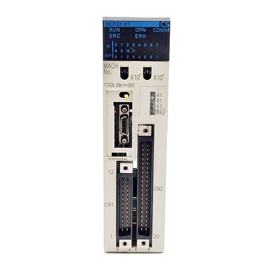
Names and Functions of Parts Section 3-1 Names and Functions of Parts 3-1-1 Names and Functions of Parts CS1W-HIO01-V1 Front View Side View Rear View HIO01-V1 Indicators COMM COMM IN IN 0 1 2 3 4 5 6 7 Unit number switches 8 9 10 10 11 0 1 2 3 4 5 6 7... - Page 57 Names and Functions of Parts Section 3-1 CS1W-HCA12-V1 Front View Side View Rear View HCA12-V1 Indicators COMM 0 1 2 3 4 5 6 7 IN IN 8 9 10 10 11 Unit number switches 0 1 2 3 4 5 6 7 MACH (Rotary switches): Setting range: 0 to 95...
- Page 58 V1, and pulse inputs, analog input and analog outputs for the CS1W-HCA12- V1. Either make a cable for this connector with the 40-pin connector provided with the Unit, or using a special OMRON cable, connect to an OMRON Con- nector Terminal Conversion Unit. (For details, refer to 3-3 Wiring.)
-
Page 59: Installation
Installation Section 3-2 Indicator Name Color Status Meaning Unit error Fatal error at the Unit. Flashing A non-fatal error at the Unit, or an error at the CPU Unit. Not lit No errors at the Unit. CPU Unit error An error at the CPU Unit (fatal error, WDT error, monitor error, or bus error) or an initial setting error in the CPU Unit’s allocated words in the DM Area. -
Page 60: Mounting The Unit (All Units)
Installation Section 3-2 CS-series CPU Rack CPU Unit I/O Unit Power Supply Unit CS-series Expansion Rack No. 1 I/O Unit CS-series Expansion Rack No. 2 I/O Unit Up to 7 Expansion Racks can be connected. CS-series Expansion Rack No. 7 I/O Unit 3-2-2 Mounting the Unit (All Units) -
Page 61: Handling The Unit
Section 3-2 Installation 3. To remove the Unit, loosen the screw at the bottom of the Unit before dis- mounting. Note Provide the space shown in the diagram below to enable mounting and dis- mounting. Duct 20 mm min. Backplane 20 mm min. -
Page 62: Wiring
Wiring Section 3-3 Remove the label after wiring is completed. Wiring 3-3-1 I/O Connector Pin Arrangement (All Units) Pin arrangement Row B Row A External input 0 (Interrupt input or External input 2 (Interrupt input or normal input; bit 00000) normal input;... -
Page 63: Special I/O Connector Pin Arrangement
Wiring Section 3-3 3-3-2 Special I/O Connector Pin Arrangement CS1W-HCP22-V1 Pin arrangement Row A Pin number Row B Pulse input 1 Phase A LD–/0 V Pulse input 1 Phase A LD+ Phase A 5 V Phase A 24 V Phase B LD–/0 V Phase B LD+ Phase B 5 V Phase B 24 V... - Page 64 Wiring Section 3-3 CS1W-HCA22-V1 Pin arrangement Row A Pin number Row B Pulse input 1 Phase A LD–/0 V Pulse input 1 Phase A LD+ Phase A 5 V Phase A 24 V Phase B LD–/0 V Phase B LD+ Phase B 5 V Phase B 24 V Phase Z LD–/0 V...
-
Page 65: Wiring Examples
Wiring Section 3-3 CS1W-HCA12-V1 Pin arrangement Row A Pin number Row B Pulse input 1 Phase A LD–/0 V Pulse input 1 Phase A LD+ Phase A 5 V Phase A 24 V Phase B LD–/0 V Phase B LD+ Phase B 5 V Phase B 24 V Phase Z LD–/0 V... - Page 66 Wiring Section 3-3 Example The wiring for an encoder (24 V) with an open-collector output is shown below. These examples are for encoders with A, B, and Z phases. Customizable Counter Unit (Differential-phase Input Mode) (Pulse input 1: Phase A, 24 V) Phase A (Pulse input 1: Phase A, 0 V) Black...
- Page 67 Wiring Section 3-3 The wiring for when the encoder has a linedriver output (Am26LS31 or equiv- alent) is shown below. Customizable Counter Unit (Differential-phase Input Mode) Black (Pulse input 1: Phase A, LD+) Black with A− stripes − (Pulse input 1: Phase A, LD Encoder White (Pulse input 1: Phase B, LD+)
- Page 68 Wiring Section 3-3 Example As an example, the wiring for connection to a motor driver is shown below. 24-VDC (Do not share the power supply power with other I/O circuits.) supply Customizable Counter Unit Motor driver − Output power supply 1.6 kΩ...
-
Page 69: Wiring Methods
Wiring Section 3-3 Connection with a Servo Driver (OMRON's W Series) with an Absolute Encoder (CS1W-HCP22-V1/ HCA22-V1/HCA12-V1) Servo driver with an absolute encoder (OMRON's W series) Customizable Counter Unit Twisted-pair shielded cable Encoder phase-A output Encoder phase-B output Encoder phase-Z output... - Page 70 7. Do not bend cables beyond their natural limit. Doing so may result in dis- connection. Connectors Connections to the I/O Connector Connector type Number of pins Ordering as a Ordering individually set (OMRON) (Fujitsu) Soldered 24 pins C500-CE241 Socket: FCN-361J024-AU (See note.) Connector cover:...
- Page 71 Wiring Section 3-3 After wiring Hook Remove the label. 3. When soldering, take care not to short the terminal to the neighboring one. Cover the soldered part with an insulating tube. Soldered-type connector included with Unit Insulating tube Wire (0.2 to 0.13 mm Note Be sure to check that the output power supply is not connected in reverse.
- Page 72 Wiring Section 3-3 5. Mount the connector. Connector Customizable Counter Unit Customizable Counter Unit Connector 6. After wiring has been completed, be sure to remove the label to allow prop- er heat dissipation. After wiring Remove the label. Connector lock screw Tighten the connector lock screw to a torque of 0.2 N ×...
-
Page 73: Programming Devices
Programming Devices Section 3-4 Mounting Dimensions The dimensions when the Unit is mounted to the Rack and the cable connec- tors are connected are shown below. With soldered or crimped Fujitsu connector: Approx. 179 With pressure-welded Fujitsu connector; Connecting cable: G79-@@@C-@@@-@@@ XW2Z-@@@ Programming Devices Development, transfer, and monitoring of ladder programs, editing and moni-... - Page 74 Programming Devices Section 3-4 Compatible Programming The following Programming Devices can be used. Devices • Programming Consoles • CX-Programmer Ver. 1.2 or later (register the PLC model as a CQM1H- CPU61.) Note 1. The Customizable Counter Unit cannot be used with CX-Programmer Ver. 1.1 or earlier.
-
Page 75: Programming Consoles
Programming Devices Section 3-4 3-4-1 Programming Consoles The following three Programming Console are available: • CQM1H-PRO01 • CQM1-PRO01 • C200H-PRO27 Programming Console Connections Port at the Programming Programming Type of network Cables Customizable Device Console model (serial Model number Length Counter Unit connection communications... -
Page 76: Fail-Safe Circuits
Fail-safe Circuits Section 3-5 Connecting Cables Connecting to the Computer Computer Connecting to peripheral port IBM PC/AT or compatible IBM PC/AT computer (D-sub, 9-pin male) (9-pin, male) Customizable CS-series Counter Unit CPU Unit Peripheral port CS1W-CN226/-CN626 Connecting Cable (for IBM PC/AT or compatible) Available Connecting Cables Customizable... - Page 77 Fail-safe Circuits Section 3-5 turn OFF. Take any safety measures necessary outside of the Unit to ensure the safety of the system in the event that outputs turn OFF. Supply Power to the PLC If the PLC’s power supply is turned ON after the controlled system’s power before Outputs supply, contact outputs may malfunction momentarily and, as a result, the controlled system’s outputs may operate incorrectly for a short time.
- Page 78 Fail-safe Circuits Section 3-5...
-
Page 79: Exchanging Data With The Cpu Unit
SECTION 4 Exchanging Data with the CPU Unit This section provides details on the way in which data is exchanged between the Customizable Counter Unit and the CPU Unit. Overview ........... . 4-1-1 Overview of Data Exchange Areas . -
Page 80: Overview
Overview Section 4-1 Overview The Customizable Counter Unit exchanges data with the CPU Unit in the fol- lowing 3 areas. 1. Using allocated words in the CPU Unit’s CIO Area. 2. Using allocated words in the CPU Unit’s DM Area. 3. -
Page 81: Data Exchange Using The Words Allocated In Cio Area
Overview Section 4-1 n = CIO 2000 + (unit number ´ 10) in the CPU Unit m = D20000 + (unit number ´ 100) in the CPU Unit Method Customizable CPU Unit Special- From CPU From Custom- Timing of Specification Counter Unit words ized or... -
Page 82: Data Exchange Using The Words Allocated In Dm Area
Overview Section 4-1 Note n = 2000 + (unit number ´ 10) in the CPU Unit Customizable Counter Unit CPU Unit SR Area Words allocated in CIO Area Commands Commands General-pur- General-pur- pose words pose words Exchanged cyclically Status Status General-pur- General-pur- pose words... -
Page 83: Words Allocated In Cio Area
Words Allocated in CIO Area Section 4-2 4-1-4 Data Exchange Using the LR Area Words General-purpose data is exchanged cyclically between user-set words in the CPU Unit (e.g., in the CIO, WR, or DM Area) and the Customizable Counter Unit’s LR Area words. Customizable Counter Unit CPU Unit LR Area... - Page 84 Words Allocated in CIO Area Section 4-2 Unit number Allocated words CIO 2000 to CIO 2009 CIO 2010 to CIO 2019 CIO 2020 to CIO 2029 CIO 2030 to CIO 2039 CIO 2040 to CIO 2049 CIO 2050 to CIO 2059 CIO 2060 to CIO 2069 CIO 2070 to CIO 2079 CIO 2080 to CIO 2089...
-
Page 85: Cio Area Allocation Details
Words Allocated in CIO Area Section 4-2 4-2-2 CIO Area Allocation Details The following data is output from the CPU Unit to the Customizable Counter Unit. n = CIO 2000 + (unit number ´ 10) CPU Unit Customiz- Bits Name Function word able... - Page 86 Words Allocated in CIO Area Section 4-2 The following data is input from the Customizable Counter Unit to the CPU Unit. CPU Unit Customiz- Bits Name Function address able Counter Unit word SR 235 00 to 07 Unit error These bits are used to notify the CPU Unit of the error code code for errors that occur in the Customizable Counter Unit.
-
Page 87: Words Allocated In Dm Area
Words Allocated in DM Area Section 4-3 Words Allocated in DM Area 4-3-1 Allocated Words A total of 100 words are allocated from words in the CPU Unit’s DM Area for Special I/O Units (D20000 to D29599) according to the unit number (0 to 95) set for the Customizable Counter Unit using the rotary switches on the front of the Unit. -
Page 88: Dm Area Allocation Details
Words Allocated in DM Area Section 4-3 4-3-2 DM Area Allocation Details Initial Setting Area (m to m+9) Word Bits Function Contents Setting Condition 00 to 07 RUN/STOP Operating mode at Operating mode Operation for error command startup specification after at PLC (SR 24915 enable/disable startup... - Page 89 Words Allocated in DM Area Section 4-3 Word Bits Function Contents 00 to 07 Input and out- First word address of the output words in 00 (BCD): Disabled (i.e., no transfer put of general- the words allocated in DM Area (for output from the CPU Unit to the Customizable purpose data from the CPU Unit to the Customizable...
- Page 90 Words Allocated in DM Area Section 4-3 Note In the following circumstances, an error for the initial setting data transferred from the CPU Unit’s words allocated in DM Area occurs, and SR 24903 turns • The total number of input and output transfer words exceeds 90. •...
-
Page 91: Lr Area
LR Area Section 4-4 4-3-3 Example Allocations An example of a possible configuration for exchanging data using the words allocated in DM Area is shown below. In this example, the unit number = 0 and the first word in the words allocated in DM Area (m) is D20000. Customizable Counter Unit CPU Unit General-purpose words... -
Page 92: Difference Between I/O Refreshing In Customizable Counter Units And That In Other Special I/O Units
Difference between I/O Refreshing in Customizable Section 4-5 The configuration for exchanging data using the LR Area is set in the Unit Setup Area as shown below. 4-4-2 Unit Setup Area 08 07 Area for input words in the CPU Unit Number of input words (BCD) DM6601 Area for output words in the CPU Unit... - Page 93 Difference between I/O Refreshing in Customizable Section 4-5 Exchanging Data between a Customizable Counter Unit and the CPU Unit A CS1W-H@@@@ Customizable Counter Unit exchanges data with the CS- series CPU Unit in an asynchronous system using I/O refreshing timing on both sides.
- Page 94 Difference between I/O Refreshing in Customizable Section 4-5 Note Even if the same interval is set using the constant cycle time function, syn- chronization actually will not last long even when it does occur because the intervals are not that precise. This means that a period of overlap will be fol- lowed by a period of non-overlap.
- Page 95 Difference between I/O Refreshing in Customizable Section 4-5 Preventing the Customizable Counter Unit from Missing Consecutive I/O Refreshes ■ When the Cycle Time of the CPU Unit Can Be Changed Use the constant cycle time function on the CPU Unit to change the cycle time of the Unit so it is longer than the sum total of the cycle time for the Customiz- able Counter Unit and the I/O refresh time of the CPU Unit as expressed by the formula below.
- Page 96 Difference between I/O Refreshing in Customizable Section 4-5 Reference: The Customizable Counter Unit refreshes I/O by performing a handshake with the CPU Unit at any time (with -V1 lot No. 0302 or later Units only) The Customizable Counter Unit can refresh the I/O by performing a hand- shake with the CPU Unit at any time.
-
Page 97: Unit Setup Area
SECTION 5 Unit Setup Area This section provides details on the settings made using the Unit Setup Area in the Customizable Counter Unit. Unit Setup Area ..........5-1-1 Overview . -
Page 98: Unit Setup Area
Unit Setup Area Section 5-1 Unit Setup Area 5-1-1 Overview The Unit Setup Area enables the user to set the functions of the Customizable Counter Unit through initial software settings. Connect a Programming Device to the Unit’s peripheral port and make the settings in DM 6600 to DM 6655 of the Unit’s DM Area. - Page 99 Unit Setup Area Section 5-1 5-1-2 Details of Overall Unit Settings Settings Enabled at Startup Address Bits Function Contents DM 6600 00 to 03 Disable writing to user memory (UM protect) 0 Hex: Writing enabled 1 Hex: Writing disabled Note: Set these bits to 1 (Hex) to prohibit writing to the following areas from the Programming Device: User program, read-only...
- Page 100 Unit Setup Area Section 5-1 Settings Enabled at Startup and when Operation Starts Address Bits Function Contents DM 6615 00 to 15 Enable high-speed execution Setting other than 5A5A Hex: Normal Execution Mode 5A5A: High-speed Execution Mode DM 6616 00 to 15 (Reserved by system.) DM 6617 00 to 15 Peripheral port servicing time 0000 (BCD): Default (0.2 ms)
- Page 101 Unit Setup Area Section 5-1 Settings Enabled whenever Changed Address Bits Function Contents DM 6650 00 to 03 Communications settings for peripheral port 0 Hex: Standard settings (baud rate: 9,600 bps; data length: 7 bits; 1 start bit; 2 stop bits;...
- Page 102 Unit Setup Area Section 5-1 5-1-3 Details of Special I/O Setup Area Settings for Pulse Inputs (Enabled at Startup; CS1W-HCP22-V1/HCA22-V1/HCA12-V1 Only) Address Bits Function Details DM 6605 00 to 03 High-speed Pulse input mode 0 Hex: Differential-phase input x1 counter 1 1 Hex: Differential-phase input x2 2 Hex: Differential-phase input x4 3 Hex: Increment/decrement pulse input...
- Page 103 Unit Setup Area Section 5-1 Address Bits Function Details DM 6609 00 to 15 ABS resolution Rightmost 4 digits 0000 0001 to 0000 8000 Hex (the No. of input Note: Set the resolution considering pulses for DM 6610 00 to 15 Leftmost 4 digits servo driver's "encoder dividing rate"...
- Page 104 Unit Setup Area Section 5-1 Address Bits Function Details DM 6632 00 to 15 Ring set value for pulse output Rightmost 4 digits Same as for ring set value for counter 2 pulse output counter 1. DM 6633 00 to 15 Leftmost 4 digits Settings for Analog Inputs/Outputs (CS1W-HCA22-V1/HCA12-V1 Only) Settings Enabled at Startup...
-
Page 105: I/O Memory
SECTION 6 I/O Memory This section provides details of the settings made using the I/O memory areas in the Customizable Counter Unit. Overview ........... . 6-1-1 I/O Memory Areas . -
Page 106: Overview
Overview Section 6-1 Overview 6-1-1 I/O Memory Areas Data area Word addresses Bit addresses Size Function Input Area IR 000 IR 00000 to IR 00011 12 bits Bits in the Input Area are allocated to input terminals. These allocations are fixed and cannot be changed. - Page 107 Overview Section 6-1 Other Areas The following words in the DM Area cannot be used as I/O memory (i.e., they cannot be written to from the ladder program). Data area Addresses Size Function DM Area DM 6144 to 56 words Error Log Area DM 6199 DM 6200 to...
- Page 108 Overview Section 6-1 6-1-2 Hold/Clear for I/O Memory Data The following table shows when the status of the memory areas is held and when it is cleared. Name Addresses External I/O Operating Fatal errors Power supply allocation mode turned ON FALS error Other fatal changed...
-
Page 109: Details
Details Section 6-2 4. With the Customizable Counter Unit, there is no function (e.g., such as an IOM Hold Bit) for holding the bit status in the cleared areas above when the operating mode is changed or the power supply is turned ON. Details Explanations of the I/O memory areas in the Customizable Counter Unit are given in this section. - Page 110 Details Section 6-2 6-2-4 AR Area AR bits are used for specific functions related to the operation of the Custom- izable Counter Unit’s special I/O. For details on the functions of individual bits, refer to 6-4 AR Area. 6-2-5 LR Area This area can be used for data exchange with user-set words (in the CIO, WR, AR, HR, DM, or EM Area) in the CPU Unit.
- Page 111 Details Section 6-2 6-2-6 Timer/Counter Area This area is used to manage the TIM, TIMH(15), TMHH(––), CNT, and CNTR(12) instructions. The same numbers are used for timers and counters; do not use the same number twice even for different instructions. If TIM/CNT number is designated for word data, it will access the present value (PV);...
- Page 112 Details Section 6-2 Read-only Words in DM Area Reading is possible for these words using instructions, but writing is not possi- ble. Using a Programming Device, both reading and writing are possible. Use this area for storing data that must not be changed. Area Addresses Instructions...
-
Page 113: Sr Area
SR Area Section 6-3 SR Area In the following table, Unit in the Controlled by column indicates areas for which only reading is possible using instructions from the ladder program, and User indicates areas for which both reading and writing is possible from the ladder program. - Page 114 SR Area Section 6-3 Address Bits Function Controlled SR 235 00 to 07 For exchanging data 00 to Unit error code Unit with words allocated in Note: The error codes are also stored in CPU Unit’s CIO Area bits 00 to 07 of the error information por- (from Customizable tion of error logs.
- Page 115 SR Area Section 6-3 Address Bits Function Controlled SR 240 00 to 15 Input Interrupt 0 (IR 00000) Counter Counter SVs when input interrupts are User Mode SV used in Counter Mode (0000 to FFFF Hex). SR 241 00 to 15 Input Interrupt 1 (IR 00001) Counter Note: When input interrupts are not Mode SV...
- Page 116 SR Area Section 6-3 Address Bits Function Controlled SR 249 Turns ON when there is an error in the DM 6600 to Unit error code 9B Unit Unit Setup Area read when the power DM 6614 (Unit Setup Area supply is turned ON (non-fatal error). error) is stored in SR 23500 to Turns ON when there is an error in the...
- Page 117 SR Area Section 6-3 Address Bits Function Controlled SR 250 00 to 07 (Reserved by system.) 08 to 11 Peripheral port error code 0 Hex: No error Unit 1 Hex: Parity error 2 Hex: Framing error 3 Hex: Overrun error Note: When a Programming Device is connected using peripheral bus communications, F Hex is stored here.
-
Page 118: Ar Area
AR Area Section 6-4 Address Bits Function Controlled SR 255 0.1-second Clock Pulse (0.05 seconds ON, 0.05 seconds OFF) Unit 0.2-second Clock Pulse (0.1 seconds ON, 0.1 seconds OFF) 1.0-second Clock Pulse (0.5 seconds ON, 0.5 seconds OFF) Instruction Execution Error (ER) Flag Turns ON when an error occurs during execution of an instruction. - Page 119 AR Area Section 6-4 Pulse Inputs (CS1W-HCP22-V1/HCA22-V1/HCA12-V1 Only) Address Bits Function Details Controlled Forced set/reset AR 00 00 to 15 High-speed Counter 1 PV Rightmost Counter range: 8000 0000 to 7FFF Unit Disabled 4 digits FFFF Hex (8 digits) Note: In Linear Counter Mode, AR 01 00 to 15 Leftmost...
- Page 120 AR Area Section 6-4 Address Bits Function Details Controlled Forced set/reset AR 08 High-speed counter 1 Target OFF: In Target Comparison Mode Unit Enabled status Value for the CTBL instruction, indicates Compari- that comparison is not in progress. son Flag Note: This flag is always OFF in range comparison mode for the CTBL instruction.
- Page 121 AR Area Section 6-4 Address Bits Function Details Controlled Forced set/reset AR 08 High-speed counter 1 Measur- OFF: Measurement for high-speed Unit Enabled status ing Flag counter rate of change or fre- (measure- quency measurement is not in ment progress. modes 1 ON: Measurement for high-speed or 2)
- Page 122 AR Area Section 6-4 Address Bits Function Details Controlled Forced set/reset AR 09 High-speed counter 1 High- OFF: Stops counter operation. The User Enabled commands speed high-speed counter PV is held. Counter ON: Starts counter operation. The Start Bit high-speed counter PV is not reset.
- Page 123 AR Area Section 6-4 Address Bits Function Details Controlled Forced set/reset AR 09 ABS encoder input com- ABS offset 0: No preset User Enabled mands preset 0 to 1: Offset value obtained from multi-turn data from servo driver and the No. of initial incremental pulses are stored in ABS offset value (DM6645/6646).
- Page 124 AR Area Section 6-4 Pulse Outputs (CS1W-HCP22-V1 Only) Address Bits Function Details Controlled Forced set/reset AR 14 00 to 15 Pulse Output 1 PV Rightmost 4 dig- The pulse output PV is Unit Disabled stored in 8-digit hexa- Note: The pulse output decimal.
- Page 125 AR Area Section 6-4 Address Bits Function Details Controlled Forced set/reset AR 18 Pulse Output 1 Status Pulse Output OFF: Pulse output not Unit Enabled Completed Flag completed (stays OFF during pulse output). ON: Pulse output com- pleted (goes ON at com- pletion of pulse output) Number of OFF: Number of pulses...
- Page 126 AR Area Section 6-4 Address Bits Function Details Controlled Forced set/reset AR 19 Pulse output 1 com- PV Reset OFF: Pulse output 1 PV User Enabled mands not reset ON: Pulse output 1 PV reset Range Compari- OFF: The instruction son Result Clear execution result (AR 20) or the output bit pattern...
- Page 127 AR Area Section 6-4 Address Bits Function Details Controlled Forced set/reset AR 20 00 to 15 Pulse output 1 monitor Range compari- The instruction execu- Unit Enabled data son result tion result that is output when the CTBL instruc- tion is executed for a range comparison is stored here.
- Page 128 AR Area Section 6-4 Address Bits Function Details Controlled Forced set/reset AR 16 Analog Output 1 Con- ON: D/A conversion enabled (an analog sig- User Enabled version Enable Bit nal is output) OFF: D/A conversion is not performed (ana- log output is held at the value specified in DM 6613 and DM 6614) Analog Output 2 Con- Note: These bits are cleared when the Cus-...
- Page 129 AR Area Section 6-4 Address Bits Function Details Controlled Forced set/reset AR 18 Analog Output 1 ON: Adjustment enabled User Enabled Adjustment Enable OFF: Adjustment disabled Analog Output 2 Enabled in adjustment mode (DM 6631 in Adjustment Enable Unit Setting Area set to 5A5A Hex). Adjusted Mode Specifies either the offset value or the gain Adjustment Item...
- Page 130 AR Area Section 6-4 Analog Inputs/Pulse Inputs/Analog Outputs (CS1W-HCA12-V1 Only) Address Bits Function Details Controlled Forced set/reset AR 00 00 to 15 High-speed Counter 1 Rightmost Counter range: 8000 0000 to 7FFF Unit Disabled 4 digits FFFF Hex (8 digits hexadecimal) AR 01 00 to 15 Leftmost...
- Page 131 Section 6-4 AR Area Address Bits Function Details Controlled Forced set/reset AR 08 High-speed counter 1 Target Value OFF: In Target Comparison Mode Unit Enabled status Comparison for the CTBL instruction, indicates Flag that comparison is not in progress. Note: This flag is always OFF in range comparison mode for the CTBL instruction.
- Page 132 AR Area Section 6-4 Address Bits Function Details Controlled Forced set/reset AR 08 High-speed counter 1 Measuring OFF: Measurement for high-speed Unit Enabled status Flag (mea- counter rate of change or frequency surement measurement is not in progress. modes 1 or ON: Measurement for high-speed counter rate of change or frequency measurement is in progress.
- Page 133 AR Area Section 6-4 Address Bits Function Details Controlled Forced set/reset AR 09 High-speed counter 1 High-speed OFF: Stops counter operation. The User Enabled commands Counter high-speed counter PV is held. Start Bit ON: Starts counter operation. The high-speed counter PV is not reset. High-speed OFF: If the counter reset method is Counter...
- Page 134 AR Area Section 6-4 Address Bits Function Details Controlled Forced set/reset AR 09 ABS encoder input ABS offset 0: No preset User Enabled commands preset 0 to 1: Offset value obtained from multi-turn data from servo driver and the No. of initial incremental pulses are stored in ABS offset value (DM 6645/6646).
- Page 135 AR Area Section 6-4 Address Bits Function Details Controlled Forced set/reset AR 16 Analog Output 1 Con- ON: D/A conversion enabled (an analog signal is User Enabled version Enable Bit output) OFF: D/A conversion is not performed (analog out- put is held at the value specified in DM 6613 and DM 6614) Analog Output 2 Con- Note: These bits are cleared when the Customiz-...
- Page 136 AR Area Section 6-4 Address Bits Function Details Controlled Forced set/reset AR 18 Adjustment mode Analog Adjust- ON: Adjustment invalid User Enabled command (valid when Input/Ana- ment OFF: Adjustment valid DM6631 = 5A5A Hex) log Output 1 enable At the rise of this bit, an ini- Analog Out- tial value (offset or gain) put 2...
- Page 137 AR Area Section 6-4 Address Bits Function Details Controlled Forced set/reset AR 19 00 to 15 Adjustment mode Analog Input Offset Under the condition of Unit Disabled command (valid when value adjustment enable flag (AR DM6631 = 5A5A Hex) 08 bit 00/03) being ON, analog input offset value can be monitored here.
- Page 138 AR Area Section 6-4...
-
Page 139: Special Functions
SECTION 7 Special Functions This section provides information on interrupts, pulse inputs, pulse outputs, and analog outputs. Outline ............Interrupt Functions . - Page 140 7-8-12 Sample Programs (with the Connection to OMRON's W Series Servo Driver) ..Analog Input Functions ......... .
-
Page 141: Outline
Section 7-1 Outline Outline The functions of the Customizable Counter Unit are outlined in the following illustrations. Customizable Counter Unit Basic interrupts Input interrupts 4 inputs (Input Interrupt or Counter Mode) CS1W-HIO01-V1/ HCP22-V1/HCA22-V1 Interval timer interrupts Scheduled interrupts 1 timer, SV: 0.5 to 99,990 ms Unit: 0.1 ms One-shot interrupts Constant Cycle Time Over... -
Page 142: Interrupt Functions
Interrupt Functions Section 7-2 Interrupt Functions 7-2-1 Overview The Customizable Counter Unit supports the following interrupts. Executing Interrupt Programs in the Customizable Counter Unit The interrupt routines that are executed for all of the following interrupts are programmed as subroutines. Subroutines are defined between SBN(92) and RET(93) following the main program. -
Page 143: Disabling And Enabling All Interrupts
Interrupt Functions Section 7-2 The following program sections show how to handle this problem. Method 1 Method 2 Disabling all interrupts in the main Executing in the main program Programming in subrou- program when controlling a port instructions that could not be tine for method 2 executed in a subroutine Always... -
Page 144: Interrupt Inputs
Interrupt Inputs Section 7-3 Note Enabling interrupts merely returns the interrupts to the status they were in before they were disabled. If an interrupt was masked before it was disabled, it will still be masked after it is enabled. Interrupt Inputs 7-3-1 Applicable Models Model numbers... -
Page 145: Executing Interrupt Tasks In The Cpu Unit
Executing Interrupt Tasks in the CPU Unit Section 7-4 Executing Interrupt Tasks in the CPU Unit 7-4-1 Applicable Models Model numbers Functions CS1W-HIO01-V1 12 contact inputs, 8 contact outputs CS1W-HCP22-V1 12 contact inputs, 8 contact outputs, 2 pulse inputs, 2 pulse outputs CS1W-HCA22-V1 12 contact inputs, 8 contact outputs, 2 pulse inputs, 2 analog outputs CS1W-HCA12-V1... -
Page 146: Pulse Inputs
Pulse Inputs Section 7-5 Pulse Inputs 7-5-1 Applicable Models Model numbers Functions CS1W-HCP22-V1 12 contact inputs, 8 contact outputs, 2 pulse inputs, 2 pulse outputs CS1W-HCA22-V1 12 contact inputs, 8 contact outputs, 2 pulse inputs, 2 analog outputs CS1W-HCA12-V1 12 contact inputs, 8 contact outputs, 1 analog input, 1 pulse input, 2 analog outputs 7-5-2 Outline... - Page 147 Pulse Inputs Section 7-5 Item Specification High-speed counter PV storage locations Port 1: AR 01 (upper bytes) and AR 00 (lower bytes) Port 2: AR 03 (upper bytes) and AR 02 (lower bytes) Target value or range comparison can be performed for the above values. These values are updated during the I/O refresh period of the Customizable Counter Unit.
- Page 148 Pulse Inputs Section 7-5 Item Specification Minimum response pulse At 50 kHz Encoder Inputs A and B Encoder Inputs A and B Signal rise and fall must be 3 μs max. Square waveform 50-kHz pulse with 50% duty ratio 50-kHz pulse with 50% duty ratio 20 μs min.
-
Page 149: Internal Circuit Configurations
Pulse Inputs Section 7-5 Applicable Instructions Instruction Control Description (@)CTBL(63) Range comparison One range comparison executed. Target value comparison table regis- Target value comparison table registered and comparison tration and starting comparison started. Target value comparison table regis- Target value comparison table registered. tration (@)INI(61) Starting comparison... -
Page 150: Pulse Outputs
Pulse Outputs Section 7-6 Pulse Outputs 7-6-1 Applicable Models Model numbers Functions CS1W-HCP22-V1 12 contact inputs, 8 contact outputs, 2 pulse inputs, 2 pulse outputs 7-6-2 Outline The CS1W-HCP22-V1 Customizable Counter Unit provides 2 pulse outputs. The pulse outputs can be used for the following functions. Note Set the pulse output mode for each output in User Setup Area words DM 6613 and DM 6614. -
Page 151: Specifications
Pulse Outputs Section 7-6 7-6-3 Specifications Item Specification Acceleration/ decelera- None tion Trapezoid None None (acceleration or Yes with separate deceleration) acceleration and deceleration rates Instructions for inde- PULS + SPED PULS (Electronic Cam PULS + ACC PLS2 pendent-mode posi- Mode) tioning Instructions for contin-... - Page 152 Pulse Outputs Section 7-6 Item Specification Number of pulse out- 1) Relative pulse output: 0000 0000 to FFFF FFFF Hex puts 2) Linear-mode absolute pulse output: 8000 0000 to 7FFF FFFF Hex 3) Ring-mode absolute pulse output: 0000 0000 to Ring set value Hex 4) Electronic cam mode (linear) (output with absolute position specification): 8000 0000 to 7FFF FFFF Hex 5) Electronic cam mode (ring) (output with absolute position specification):...
- Page 153 Pulse Outputs Section 7-6 One-shot Pulse Outputs Item Specification Number of pulse 2 outputs (Port 1 = pulse output 1, port 2 = pulse output 2) outputs External power 24 VDC +10%/–15%, 30 mA max. supply NPN open-collector, 80 mA at 5 to 24 VDC ±10% Max.
- Page 154 Pulse Outputs Section 7-6 Applicable Instructions The following seven instructions can be used to control pulse outputs. The relationship between the instruction and the types of pulse output that is pos- sible is also listed in the following table. Instruction Control Independent Positioning Mode Continuous Speed Control...
-
Page 155: Precaution In Using Pulse Outputs
Pulse Outputs Section 7-6 7-6-4 Precaution in Using Pulse Outputs Pulses are output from the CS1W-HCP22-V1 according to the clock fre- quency specified in the Unit Setup Area (bits 08 to 15 of DM 6613 and DM 6614: 25 MHz, 6.25 MHz, 1.5625 MHz, or 390.625 kHz). The clock signal is divided by an integer dividing ratio to create and output the output pulse fre- quency. -
Page 156: Speed-Changing Cycle Selection Of Acc/Pls2 Instructions And
Pulse Outputs Section 7-6 7-6-5 Speed-Changing Cycle Selection of ACC/PLS2 Instructions and Widening of Acceleration/Deceleration Setting Ranges With the -V1 unit with lot No. 0209__ or later, the speed-changing cycle for acceleration and deceleration of ACC and PLS2 instructions can be selected from 1 ms or 2 ms. - Page 157 Pulse Outputs Section 7-6 direction designated by the absolute position (pulse output direction was the only priority mode). Pulse Output Direction In this mode, the user determines the pulse output direction using an oper- Priority Mode and. Pulses are output only if the output direction designated by PLS2 instruc- tion is the same as the output direction designated by the absolute position.
-
Page 158: Analog Outputs
Analog Outputs Section 7-7 Absolute Position Execute the PLS2 instruction with bit 14 in AR 19 turned ON. Designation Priority Mode AR 19.14 Normal ON Execute condition @PLS2 Pulse output 1 Ignored because the direction changes automatically. DM 0000 Setting table: DM 0000 DM 0000 8000 Target position: 8000... - Page 159 Analog Outputs Section 7-7 Item Specification Analog output refresh method Refreshing of analog outputs is set in the Unit Setup Area (DM 6630 bits 00 to 07 for both ports) to one of the following: END refresh Immediate refresh via SPED or ACC execution END refresh If the Analog Output Conversion Enable Bit is ON (port 1: AR 1600, port 2: AR 1601), the value in AR 14 or AR 15 is output after pro-...
- Page 160 Analog Outputs Section 7-7 Note 1. Accuracy applies to full scale. 2. Analog outputs are treated as described in the following table for fatal er- rors in the Customizable Counter Unit or CPU standby status for the CPU Unit. Condition Analog output WDT error in Customizable Counter Unit Output near 0 V (0 V if no offset is set).
- Page 161 Section 7-7 Analog Outputs Applicable Instructions END Refresh Use instructions, such as MOV, to store the analog output value in AR 14 and AR 15 and then turn ON the Analog Output Conversion Enable Bit (AR 1600 or AR 1601). Immediate Refresh Using Instructions Outputs can be controlled with SPED and ACC as outlined below.
-
Page 162: Functions Compatible With Servo Drivers With Absolute Encoders
Either of the following types of pulse input signals can be input to the unit: • Pulse trains from normal incremental encoders, etc. • Encoder output data (Ex: OMRON's W series, etc.) of servo drivers with absolute encoders (multi-turns absolute encoders) The following explains the functions that are compatible with the latter, servo drivers with absolute encoders. -
Page 163: Data Format Of Absolute Encoder Output
Functions Compatible with Servo Drivers with Absolute Encoders Section 7-8 Customizable Counter Unit Servo driver Analog output (Speed control) −10 to 10 V, etc. Position control, (SPED, ACC, Speed PULS or PLS2 control SEN signal instruction) Absolute encoder data Power cable (U, V, W) Absolute encoder signal (line driver) -
Page 164: Counting Mode
Functions Compatible with Servo Drivers with Absolute Encoders Section 7-8 5. When the mode where the data on the number of rotations is output only in the + direction is set in the absolute encoder multi-turn limit setting, the data received by the unit is handled as described below according to the setting of "high-speed counter 1 operating mode"... -
Page 165: Abs Present Value
Functions Compatible with Servo Drivers with Absolute Encoders Section 7-8 number of rotations present value. The stored value is to follow the following conversion formula: "ABS number of rotations present value (AR 04 to 05)" = R x M "The number of Initial incremental pulses (AR 00 to 01)" = P M: Multi-turn data (meaning how many times the axis of a rotary encoder rotated) R (DM 6609, DM 6610): The number of pulses for encoder's one revolution... -
Page 166: Abs Present Value Preset
Functions Compatible with Servo Drivers with Absolute Encoders Section 7-8 7FFF ABS encoder's position Point of reference (ABS offset) ABS Present Value Note In ABS ring mode, the ABS number of rotations present value (AR 04/05) is not used; only the initial incremental pulses are used. The initial incremental pulses are the data of an amount treated as the angle from an origin. -
Page 167: Related Areas
Functions Compatible with Servo Drivers with Absolute Encoders Section 7-8 7-8-9 Related Areas Unit Setup Area Address Bits Function Details DM 6605 00 to 03 High-speed Pulse input mode 0 Hex: Differential-phase input x1 counter 1 1 Hex: Differential-phase input x2 2 Hex: Differential-phase input x4 3 Hex: Increment/decrement pulse input 4 Hex: Pulse + direction... - Page 168 Functions Compatible with Servo Drivers with Absolute Encoders Section 7-8 Auxiliary memory area Address Bits Function Details Controlled Forced set/reset AR 00 00 to 15 High-speed Counter 1 PV Rightmost Counter range: 8000 0000 to 7FFF Unit Disabled 4 digits FFFF Hex (8 digits hexadecimal) Note: In Linear Counter Mode, AR 01...
-
Page 169: Overview Of Absolute Encoder Output Data Acquire
Functions Compatible with Servo Drivers with Absolute Encoders Section 7-8 Address Bits Function Details Controlled Forced set/reset AR 09 ABS encoder input com- ABS offset 0: No preset User Enabled mands preset 0 to 1: Offset value obtained from multi-turn data from servo driver and the No. - Page 170 Functions Compatible with Servo Drivers with Absolute Encoders Section 7-8 • ABS linear (CW+) mode (DM 6605 bit 12 to 15: 4 Hex) • ABS ring mode (DM 6605 bit 12 to 15: 3 Hex) Also, set "high-speed counter 1 operating mode (DM 6605)" in the unit setup area corresponding to the setting of reverse rotation mode on the servo driver.
-
Page 171: Servo Drivers With Absolute Encoders
Functions Compatible with Servo Drivers with Absolute Encoders Section 7-8 ■ Step 4 (Required) “ABS Present Value Preset” Storing ABS present value in "high-speed counter present value 1 (AR 00 to 01)" using ABS present value preset function Store "ABS present value" in "high-speed counter present value 1 (AR 00 to 01)"... -
Page 172: Sample Programs
Functions Compatible with Servo Drivers with Absolute Encoders Section 7-8 7-8-12 Sample Programs (with the Connection to OMRON's W Series Servo Driver) Program Description 1. With the unit set to "monitor" mode, turning ON the bit 0.01 (ABS origin de- fine) presets the ABS origin in DM 6645/6646. - Page 173 Functions Compatible with Servo Drivers with Absolute Encoders Section 7-8 0.01 000005 (000026) 2.01 ABS origin ABS origin define PV preset as ABS offset 40 ms after completing ABS No. of rotations read 000006 (000028) 2.01 AR9.07 AR8.05 AR8.04 TIMH (15) ABS origin ABS No.
-
Page 174: Analog Input Functions
Analog Input Functions Section 7-9 Analog Input Functions 7-9-1 Applicable Models Model numbers Functions CS1W-HCA12-V1 12 contact inputs, 8 contact outputs, 1 analog input, 1 pulse input, 2 analog outputs 7-9-2 Overview This unit executes high-speed input of analog input signals (A/D conversion time: 50 m s). -
Page 175: Specification Of Analog Input Functions
Analog Input Functions Section 7-9 7-9-3 Specification of Analog Input Functions Item Specification Input signals Voltage inputs, current inputs No. of analog inputs 1 input Input signal ranges Select from the followings in the unit setup area (DM 6612 (analog input range)): -10 to +10 V, 0 to 10 V, 0 to 5 V, 1 to 5 V, or 4 to 20 mA 50 ms A/D conversion time... -
Page 176: Related Areas
Analog Input Functions Section 7-9 7-9-4 Related Areas Unit Setup Area Address Bits Function Details 00 Hex: -10 to +10 V DM 6612 00 to 07 Analog input Analog input range 01 Hex: 0 to 10 V 02 Hex: 1 to 5 V (4 to 20 mA) 03 Hex: 0 to 5 V DM 6630 08 to 15... - Page 177 Analog Input Functions Section 7-9 Address Bits Function Details Controlled Forced set/reset AR 18 Adjustment mode Analog Adjust- ON: Adjustment invalid User Enabled command (valid Input/Ana- ment OFF: Adjustment valid when DM6631 = log Output 1 enable At the rise of this bit, an initial 5A5A Hex) Analog Out- value (offset or gain) corre-...
-
Page 178: Applicable Instructions
Analog Input Functions Section 7-9 Address Bits Function Details Controlled Forced set/reset AR 19 00 to 15 Adjustment mode Analog Input Offset Under the condition of adjust- Unit Disabled command (valid value ment enable flag (AR 08 bit when DM6631 = 00/03) being ON, analog input 5A5A Hex) offset value can be monitored... - Page 179 Analog Input Functions Section 7-9 ■ Signal range: 10 V Analog input (V) +11.0 V +10.0 V 0.0 V −10.0 V −11.0 V Stored value 1F40 2260 DDA0 E0C0 0000 (4 digit Hexadecimal) Resolution of 1/16,000 ■ Signal range: 0 to 10 V Analog input (V) +10.5 V +10.0 V...
- Page 180 Analog Input Functions Section 7-9 ■ Signal range: 1 to 5 V/4 to 20 mA Analog input (V) Analog input (mA) +20.8 mA +5.2 V +20.0 mA +5.0 V +4.0 mA +1.0 V +0.8 V +3.2 mA Stored value 0000 0FA0 1068 FF38...
-
Page 181: Virtual Pulse Output Function (-V1 Unit With Lot No. 0209
Virtual Pulse Output Function (-V1 unit with lot No. 0209__or later only) Section 7-10 7-10 Virtual Pulse Output Function (-V1 unit with lot No. 0209__or later only) 7-10-1 Applicable Models Model numbers Functions CS1W-HCP22-V1 12 contact inputs, 8 contact outputs, 2 pulse inputs, 2 pulse outputs CS1W-HCA22-V1 12 contact inputs, 8 contact outputs, 2 pulse inputs, 2 analog outputs CS1W-HCA12-V1... -
Page 182: Pls2 Instruction (Use In Virtual Pulse Output Function)
Virtual Pulse Output Function (-V1 unit with lot No. 0209__or later only) Section 7-10 Ex 3) Position Control in Arranging a ladder program that creates an error counter, based on the inter- Semi-closed Loop on nal pulse counts and feed back signals from the servo driver, enables the Servo Motor Driver of position control in semi-closed loop method on the servo motor driver of ana- Analog Input Type... - Page 183 Virtual Pulse Output Function (-V1 unit with lot No. 0209__or later only) Section 7-10 Address Name Description Setting range Setting/ monitor Target position (8- Set the number of virtual output Relative mode: Setting digit hexadecimal) pulses here. 0000 0000 to FFFF FFFF Absolute mode: 8000 0000 to 7FFF FFFF Target frequency (4-...
-
Page 184: Application Example
Virtual Pulse Output Function (-V1 unit with lot No. 0209__or later only) Section 7-10 time match with each other. (Set the constant cycle time in DM 6619 of the unit setup area.) • When specified target position, target frequency, and acceleration/decel- eration do not lead to the trapezoidal control, the system will operate in the following manners to correct the conditions automatically and execute operations:... -
Page 185: Constant Cycle Time Over Clear Function
Constant Cycle Time Over Clear Function Section 7-11 7-11 Constant Cycle Time Over Clear Function 7-11-1 Applicable Models Model numbers Functions CS1W-HIO01-V1 12 contact inputs, 8 contact outputs CS1W-HCP22-V1 12 contact inputs, 8 contact outputs, 2 pulse inputs, 2 pulse outputs CS1W-HCA22-V1 12 contact inputs, 8 contact outputs, 2 pulse inputs, 2 analog outputs CS1W-HCA12-V1... -
Page 186: Ladder Library Function
Ladder Library Function Section 7-12 Cycle Time The function is canceled The fixed cycle time The constant cycle time function will be valid again. Constant cycle time value The actual cycle time Time Constant Cycle Time Exceeded SR 24905 CONSTANT CYCLE TIME OVER clear SR 25207 ON during 1 scan 7-11-3 Special Auxiliary Bit... - Page 187 Ladder Library Function Section 7-12 ■ Encapsulating Partial Programs (Subroutine Program Group) as a Ladder Library Creating a Ladder Library Customizable Counter Unit Flash memory Subroutine program Ladder library set flag program Ladder library Encapsulating Information on allocation of the extended special instructions Executing the Ladder Library...
-
Page 188: Features Of The "Ladder Library
Ladder Library Function Section 7-12 ■ Encapsulating an Entire Program as a lAdder Library Creating a Ladder Library Customizable Counter Unit Ladder library Flash memory set flag Ladder Entire program Encapsulating library Unit setup area Executing the Ladder Library Customizable Counter Unit Flash memory The ladder library executed at starting... -
Page 189: Creating A Ladder Library
Ladder Library Function Section 7-12 7-12-4 Creating a Ladder Library Procedure for Creating a Follow the procedure below to create a "ladder library". Make sure to start the Ladder Library procedure with erasing the existing ladder library in the unit: Entire ladder program Encapsulate entire or partial program? - Page 190 Ladder Library Function Section 7-12 Additionally, it is possible to create a ladder library with multiple subroutine programs at once. SBN must be used. Only subroutine numbers 000 to 049 can be used in ladder library. The macro argument area can Processing series be used to pass arguments to the ladder library program.
-
Page 191: Erasing A Ladder Library
Ladder Library Function Section 7-12 Step 3. Setting Ladder • Decide the method of executing a ladder library. Library Execution Mode, a The ladder library executing method can be set in the following unit setup Ladder Library ID, and a area: Ladder Library Name Item... - Page 192 Ladder Library Function Section 7-12 When a ladder library has been created with "partial programs (subroutine program group)", MCRO mode (called and executed with MCRO instruction) is used to execute the library. MCRO mode Boot mode MCRO Dummy subroutine The ladder library is executed at starting an operation.
-
Page 193: Checking The Name Of A Ladder Library
Ladder Library Function Section 7-12 Call the ladder library program with a subroutine number 200 higher than the one used when creating the ladder library program. For example, if subroutine number 030 was used when creating the ladder library program, use subroutine number 230. -
Page 194: Related Areas
Ladder Library Function Section 7-12 7-12-8 Related Areas Unit Setup Area Address Bits Function Contents DM 6624 00 to 15 Ladder library execution mode Specify either "Boot mode execution" where a ladder library stored in the Flash is opened and executed at starting an oper- ation, or "execution with MCRO instruction"... -
Page 195: Back Up Function
Back Up Function Section 7-13 7-13 Back Up Function 7-13-1 Applicable Models Model numbers Functions CS1W-HIO01-V1 12 contact inputs, 8 contact outputs CS1W-HCP22-V1 12 contact inputs, 8 contact outputs, 2 pulse inputs, 2 pulse outputs CS1W-HCA22-V1 12 contact inputs, 8 contact outputs, 2 pulse inputs, 2 analog outputs CS1W-HCA12-V1 12 contact inputs, 8 contact outputs, 1 analog input, 1 pulse input, 2 analog outputs... -
Page 196: Back Up Of Unit Memory By Bit Manipulation
Back Up Function Section 7-13 (Refer to Back Up of Unit Memory by Bit Manipulation on page 176 for details.) Conditions for Executing Condition for Executing Back Up Back Up/Restore Data cannot be backed up in the memory card of CPU unit in the following case: •... - Page 197 Back Up Function Section 7-13 Customizable Counter Unit CPU Unit Back up data write (SR 23006) Back up data read (SR 23007) Flash memory Memory card 1. User program 2. DM area only for general- purpose READ Backing up data 3.Unit setup area (DM 6600 to 6655) Restoring data...
-
Page 198: Improved Instructions
Improved Instructions Section 7-14 CIO Area Allocation Details (n = CIO 2000 + (Unit Number ´ 10)) Direction CPU Unit Bits Name Function word address Output Back up data OFF to ON: Commands to write back up data in the unit to write memory card inserted in CPU unit (At rise) Corresponds to SR 230, bit 06 of special auxiliary bits in the... -
Page 199: Apr Instruction
Improved Instructions Section 7-14 7-14-2 APR Instruction Signed BIN 16/32 Bit Overview Linear Approximation All -V1 units, as well as CS1-H CPU units, can use "signed 16/32 bit data" Operation with APR instruction. Explanation of Operations @APR T: First word address of linear data S: Word address of input data D: First word address of storage location for cal- culation result... - Page 200 Improved Instructions Section 7-14 Content of the First Word Address of Linear Data (T) 14 13 12 11 m−1 (00 to FFHex) m: Number of coordinates minus one (0 < m < 257) Input data S 00: The data in word address which is specified in S 01: High-speed counter 1 PV 11: High-speed counter 2 PV Data length specification for S and D...
- Page 201 Improved Instructions Section 7-14 In 32 Bit [D]: Calculation result (rightmost 4 digits) [D+1]: Calculation result (leftmost 4 digits) In 16 Bit [D]: Calculation result (4 digits) SIN/COS Calculation Overview With -V1 unit with lot No. 0209__ or later, the APR instruction enables the "SIN/COS Calculation"...
-
Page 202: Avg Instruction
Improved Instructions Section 7-14 S+1 CH S CH D CH Operand Value #0002 0000 0000 to 0FFF FFFF (Hex) 0000 to 3FFF (Hex) 7-14-3 AVG Instruction Signed Average Value Overview Operation All -V1 units, as well as CS1-H CPU units, can use "signed data" with AVG instruction. - Page 203 Improved Instructions Section 7-14 culated at each cycle based on the latest present values, and stored in word D. • Fractions of average values are round up.
- Page 204 Improved Instructions Section 7-14...
-
Page 205: Unit Operation And Processing Time
SECTION 8 Unit Operation and Processing Time This section explains the internal processing of the Customizable Counter Unit, and the time required for processing and execution. Customizable Counter Unit Operation ......8-1-1 Operation Flowchart . -
Page 206: Customizable Counter Unit Operation
Customizable Counter Unit Operation Section 8-1 Customizable Counter Unit Operation This section explains the internal processing of the Customizable Counter Unit. 8-1-1 Operation Flowchart The overall flow of Customizable Counter Unit operation is as shown in the fol- lowing flowchart. Power application Initialization Initialization of I/O, Work, AR, other... -
Page 207: Power Interruptions
Power Interruptions Section 8-2 8-1-2 Operational Characteristics and Precautions in Using Flash Memory 1,2,3... 1. If the contents of read-only DM Area words (DM 6200 to DM 6599) or the User Setup Area (DM 6600 to DM 6655) are changed in the Customizable Counter Unit and the power is turned OFF without switching from PRO- GRAM to RUN or MONITOR mode, the changed contents in RAM will not be written to flash memory and will be lost if power remains OFF longer... - Page 208 Power Interruptions Section 8-2 85% of the rated voltage or less AC: 10 ms 0 ms DC: 5 ms 25 ms Time AC: 0 to 10 ms DC: 0 to 5 ms Power interruption not detected; operation continues. Power supply voltage AC: 10 to 25 ms DC: 5 to 25 ms...
-
Page 209: Cycle Time
Cycle Time Section 8-3 8-2-2 Startup Operation after a Power Interruption The Customizable Counter Unit will start operating in any one of the following cases depending on the status of the RUN/STOP Command Bit (word n bit 00) and the RUN/STOP Command Enable/Disable and Operating Mode at Startup (word m bits 00 to 07): •... - Page 210 Cycle Time Section 8-3 Cycle Time and Operation The effects of the cycle time on Customizable Counter Unit operation are as listed below. Cycle time Operation conditions 10 ms or longer CYCLE TIME OVER detected and SR 23509 turns ON. TIMH will not time accurately. 20 ms or longer Programming using the 0.02-second Clock Bit (SR 25401) may be inaccurate.
-
Page 211: Instruction Execution Times
Cycle Time Section 8-3 8-3-2 Instruction Execution Times Basic Instructions Normal: Normal Execution Mode, Fast: High-speed Execution Mode Code Mnemonic ON execution Conditions OFF execution time (ms) time (ms) RSET Normal: 0.4 LD NOT Fast: Normal: 0.3 AND NOT Fast: OR NOT AND LD Normal: 0.1... - Page 212 Cycle Time Section 8-3 Code Mnemonic Conditions (Top: min.; bottom: max.) OFF execution time (ms) execution time (ms) TIMH Reset 5.0 Constant for SV 5.2 *DM for SV 12.2 12.1 WSFT 8.1 With 1-word shift register 11.1 With 10-word shift register 532.5 With 1,024-word shift register using *DM 3,084.7 With 6,144-word shift register using *DM 4.6 When comparing a constant to a word...
- Page 213 Cycle Time Section 8-3 Code Mnemonic Conditions (Top: min.; bottom: max.) OFF execution time (ms) execution time (ms) 8.1 Constant V word ® word XORW 9.0 Word V word ® word 22.7 *DM V *DM ® *DM 8.2 Constant V word ® word XNRW 9.1 Word V word ®...
- Page 214 Cycle Time Section 8-3 Code Mnemonic Conditions (Top: min.; bottom: max.) OFF execution time (ms) execution time (ms) BSET 8.1 When setting a constant to 1 word 11.1 When setting word constant to 1 word 396.5 When setting *DM to 1,024 words 2.26 ms When setting *DM to 6,144 words 82.5 When setting *EM to 2,048 words 8.7 Word ®...
- Page 215 Cycle Time Section 8-3 Code Mnemonic Conditions (Top: min.; bottom: max.) OFF execution time (ms) execution time (ms) IORF 7.7 Refreshing one input word 6.2 Refreshing one output word 7.7 Refreshing I/O words MCRO 21.3 With word-set I/O operands 33.7 With *DM-set I/O operands 10.9 Executing interrupt in CPU Unit Expansion Instructions Code...
- Page 216 Cycle Time Section 8-3 Code Mnemonic Conditions execution execution time (ms) time (ms) CTBL High-speed counters 1 and 2 or pulse output from ports 1 and 2 on CS1W-HCP22-V1/HCA22-V1: 38.3 Target table with 1 target in word and start 44.1 Target table with 1 target in *DM and start 424.3 Target table with 48 targets and start, EM not held 450.3 Target table with 48 targets and start, EM held 450.3 Target table with 16/48 targets in *DM and start...
- Page 217 Cycle Time Section 8-3 Code Mnemonic Conditions execution execution time (ms) time (ms) STIM 22.0 Word-set one-shot interrupt start 27.2 *DM-set one-shot interrupt start 22.0 Word-set scheduled interrupt start 30.4 *DM-set scheduled interrupt start 24.2 Word-set timer read 33.6 *DM-set timer read 6.8 Word-set timer stop 32.2 One-shot pulse output for CS1W-HCP22-V1 36.6 *DM-set one-shot pulse output for CS1W-HCP22-V1...
- Page 218 Cycle Time Section 8-3 Code Mnemonic Conditions execution execution time (ms) time (ms) 10.4 Constant ¸ word ® word 11.6 Word ¸ word ® word 25.9 *DM ¸ *DM ® *DM 30.4 Word ¸ word ® word DBSL 46.9 *DM ¸ *DM ® *DM 13.3 Searching word, results to word 512.5 Searching 999 words via *DM, results to *DM 10.2 Constant ´...
-
Page 219: I/O Response Time
Cycle Time Section 8-3 8-3-3 I/O Response Time The I/O response time is the time it takes after an input signal has been received (i.e., after an input bit has turned ON) for the Customizable Counter Unit to check and process the information and to output a control signal (i.e., to output the result of the processing to an output bit). -
Page 220: Interrupt Processing Time
Cycle Time Section 8-3 Maximum I/O Response The Customizable Counter Unit takes longest to respond when it receives the Time input signal just after the input refresh phase of the cycle, as shown in the illustration below. In that case, a delay of approximately one cycle will occur. Input I/O refresh point... - Page 221 Cycle Time Section 8-3 Online Editing: Interrupts will be masked for a maximum of 1,200 ms when online editing is executed during operation. Data Exchange with CPU Unit Interrupts will be disabled when processing for data exchange with the CPU Unit is being performed.
- Page 222 Cycle Time Section 8-3...
-
Page 223: Troubleshooting
SECTION 9 Troubleshooting This section provides information on troubleshooting errors that can occur with the Customizable Counter Unit. Types of Troubleshooting Information......Error Log . -
Page 224: Types Of Troubleshooting Information
Types of Troubleshooting Information Section 9-1 Types of Troubleshooting Information The Customizable Counter Unit records error information when an error occurs in the Customizable Counter Unit or in the CPU Unit. The following types of information are recorded in the Customizable Counter Unit. Error Flags One of the error flags will be turned ON to indicate when an error has occurred. -
Page 225: Error Log Contents
Error Log Section 9-2 9-2-1 Error Log Contents The error log is stored in DM 6569 through DM 6599 as shown below. Number of error records between 0000 and 000B Hex (0 to 11 decimal). DM6144 Number of records Special I/O Unit error code in DM6145 SIOU error code hexadecimal. -
Page 226: Troubleshooting Tables
Troubleshooting Tables Section 9-3 Error Log Storage The error log storage method is set in the Unit Setup Area in DM 6655, bits 00 Methods to 03). Set any of the following methods. 1. 0 Hex: You can store the most recent 11 error log records and discard older records. -
Page 227: Fatal Errors
Troubleshooting Tables Section 9-3 9-3-1 Fatal Errors Any errors that occur should be investigated and remove immediately. After correcting an error, restart the PLC or clear the error from a Programming Device. Customizable Counter Unit Fatal Errors Error Unit indicators Error Error log SR 23500... - Page 228 Troubleshooting Tables Section 9-3 Error Unit indicators Error Error log SR 23500 Error Meaning and corrective message (SIOU code, flags measures RUN OPN details 1, SR 23507 details 2) Memory MEM- 0360 Hex F1 Hex Library checksum error has error ORY ERR 00 Hex 24904...
- Page 229 Troubleshooting Tables Section 9-3 Error Unit indicators Error Error log SR 23500 Error Meaning and corrective message (SIOU code, flags measures RUN OPN details 1, SR 23507 details 2) No END NO END 0360 Hex F0 Hex END(01) is not written anywhere in INST 00 Hex 23511...
-
Page 230: Non-Fatal Errors
Troubleshooting Tables Section 9-3 9-3-2 Non-fatal Errors Although Unit operation will not stop, any errors that occur should be investi- gated and remove immediately. After correcting an error, restart the PLC or clear the error from a Programming Device. Customizable Counter Unit Non-fatal Errors Error Unit indicators Error... -
Page 231: Error Codes Of Special I/O Unit And Detailed Information
Section 9-3 Troubleshooting Tables CPU Errors Resulting in Customizable Counter Unit Non-fatal Errors Error Unit indicators Error Error log SR 23500 Error Meaning and corrective measures message (SIOU code, flags RUN OPN details 1, SR 23507 details 2) CPU unit Flash Lit SYS FAIL 0360 Hex... -
Page 232: User-Defined Errors
User-defined Errors Section 9-4 User-defined Errors There are two instructions that the user can use to define errors or messages. These instructions can be used to generate warnings (non-fatal errors where the ERC flashes) or errors (fatal errors where the ERC lights). FAILURE ALARM –... -
Page 233: Troubleshooting Flowcharts
Troubleshooting Flowcharts Section 9-5 Troubleshooting Flowcharts Use the following flowcharts to troubleshoot errors that occur during opera- tion. Main Check Error Not lit Power indicator lit? Check power supply. Not lit Check for fatal errors. RUN indicator lit? Flashing or lit ERC indicator lit Check for non-fatal errors. - Page 234 Troubleshooting Flowcharts Section 9-5 Power Supply Check Power indicator not lit. Is power being Connect power supplied to Power Sup- supply. ply Unit Is Power indicator lit? Set supply voltage within Is voltage adequate? acceptable limits. (See note.) Is Power indicator lit? Are there any loose Tighten screws or terminal screws or bro-...
- Page 235 Troubleshooting Flowcharts Section 9-5 Error Check with the The following flowchart can be used to troubleshoot errors that occur while the POWER Indicator Lit POWER indicator is lit. RUN indicator not lit. Determine the cause of the error with a Correct the problem Programming Device.
- Page 236 Troubleshooting Flowcharts Section 9-5 Error Check with the RUN The following flowchart can be used to troubleshoot errors that occur while the Indicator Lit RUN indicator is lit. ERC indicator lit or flashing. Determine the cause of the error with a Programming Device. Is a fatal or non-fatal error Identify the error, eliminate its cause,...
- Page 237 Troubleshooting Flowcharts Section 9-5 I/O Check The I/O check flowchart is based on the following ladder diagram section. (LS1) (LS2) 00002 00003 00100 SOL1 00100 SOL1 malfunction. Start (See note.) Is the IR 00100 out- put indicator operat- ing normally? Check the voltage at the Wire correctly.
- Page 238 Troubleshooting Flowcharts Section 9-5 Are the IR 00002 and IR 00003 input indi- cators operating normally? From previous page Check the voltage at Check the voltage at the IR 00002 and IR Is the connector the IR 00002 and IR 00003 terminals.
- Page 239 Troubleshooting Flowcharts Section 9-5 Environmental Conditions Check Environmental conditions check Is the ambient Consider using a temperature fan or cooler. below 55°C? Is the ambient Consider using a temperature above heater. 0°C? Is the ambient humidity Consider using an between 10% and air conditioner.
- Page 240 Troubleshooting Flowcharts Section 9-5...
-
Page 241: Precautions When Using The Cx-Programmer
Appendix A Precautions when Using the CX-Programmer This appendix describes precautions and restrictions encountered when using the CX-Programmer with the Customizable Counter Unit. When using the CX-Programmer with the Customizable Counter Unit, set the Device type/CPU model to “CQM1H-CPU61.” Restrictions Due to functional differences, the following CX-Programmer functions cannot be used with the Customizable Counter Unit (because it is set at a “CQM1H-CPU61”). - Page 242 Precautions when Using the CX-Programmer Appendix A 5. Select PLC – Transfer – To PLC, check Programs and Expansion Instructions, and then click the OK Button. Specifying Operand Addresses Not Supported by the CQM1H The program cannot be transferred from the CX-Programmer to the Customizable Counter Unit if the following operand values are set for STIM or ACC.
- Page 243 Precautions when Using the CX-Programmer Appendix A • The following symbols cannot be used when inputting instruction operands. CQM1H symbol name CQM1H memory contents Customizable Counter Unit area function Function CQM1H address corresponding to CQM1H address P_Sec_Min Upper bytes: Minutes AR 18 Special I/O area (pulse out- Lower bytes: Seconds...
- Page 244 Precautions when Using the CX-Programmer Appendix A...
-
Page 245: Index
Index connectors front panel types absolute positioning wiring Connector-Terminal Block Conversion Units and analog outputs contact I/O and pulse outputs connecting acceleration/deceleration specifications accessories contact inputs standard circuit configuration advanced processing details overview number of Always OFF Flag specifications Always ON Flag contact outputs Analog Output Conversion Enable Bits failures... - Page 246 Index data fail-safe circuits automatic backup FAL(06) backing up FALS(07) exchanging with CPU Unit precaution for xiii tracing First Cycle Flag data exchange areas flags overview AR Area debugging SR Area Differential Monitor Completion Flag flash memory differential monitoring backing up DM Area xviii dimensions data contents...
- Page 247 Index details ON delay specifications interrupt processing overview disabling/enabling all interrupts I/O connector example connections to executing tasks in CPU Unit I/O connector pins maximum response time arrangement minimum response time I/O control methods priorities I/O memory timing areas types of interrupts overview interrupt programs status held or cleared...
- Page 248 Index Position Control Units power interruptions momentary interruptions Negative (N) Flag Programmable Controller Normal Execution Mode startup operation after normal interrupts power OFF processing Number of Pulses Specified Flag precautions applications changing PC operating mode circuit failures crimp terminals One-shot Interrupt Mode CX-Programmer one-shot pulse outputs cycle time...
- Page 249 Index commands error codes counter used as timer specifications details contact I/O frequencies for speed control performance interrupts SPED modes and analog outputs number of and pulse outputs PV storage location speed control range comparison by pulse output ranges speeds resetting the PV changing in Electric Cam Mode settings...
- Page 250 Index transistor outputs trapezoid frequency outputs troubleshooting flowcharts tables Underflow (UF) Flag Unit classification Unit errors codes unit numbers switches Unit Setup Area allocation and Programming Device connection and write protection details overview settings enabled at startup settings enabled at startup and start of operation Unit Setup Area Reset Bit user memory capacity exceeded...
-
Page 251: Revision History
Revision History A manual revision code appears as a suffix to the catalog number on the front cover of the manual. Cat. No. W378-E1-02 Revision code The following table outlines the changes made to the manual during each revision. Page numbers refer to the previous version. - Page 254 Schaumburg, IL USA • 847.843.7900 • 800.556.6766 • www.omron247.com OMRON CANADA, INC. • HEAD OFFICE OMRON ARGENTINA • SALES OFFICE Toronto, ON, Canada • 416.286.6465 • 866.986.6766 • www.omron.ca Cono Sur • 54.11.4787.1129 OMRON ELETRÔNICA DO BRASIL LTDA • HEAD OFFICE OMRON CHILE •...
Need help?
Do you have a question about the SYSMAC CS Series and is the answer not in the manual?
Questions and answers