Table of Contents
Advertisement
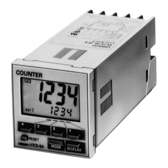
Digital Counter
Compact 1/16 DIN Counters with Easy-to-Use
Functions, Four- or Six-Digit LCD Displays
Designed for easy operation
High-speed response —
5 K counts per second
Prescale function displays
in units of actual physical
parameters — length, volume, etc.
(except A/SA types)
H7CR-C and -SC provide large/
small discrimination mode ideal
for positioning and production control
Easy-to-read backlit LCD display
On-line change of set value
4-level key protect
H7CR-S short 64 mm (2.52 in) body
Ordering Information
When placing your order, specify the supply voltage after the part number. For example, H7CR-B 100 to 240 VAC.
ECONOMY COUNTERS
Number of presets
Display type
Input type
Contact output
Sensor power supply
Counter supply voltages
STANDARD COUNTERS
Number of presets
Display type
Input type
Contact output
12 VDC sensor
supply voltage
Transistor output
Contact output
24 VDC sensor
supply voltage
Transistor output
Counter supply voltages
Number of presets
Display type
Input type
Sensor supply voltage
Output type
Contact output
Counter supply voltage
®
One
6 digit LCD, not backlit
No-voltage
H7CR-A
H7CR-AS
Not available
100 to 240 VAC, 50/60 Hz or 24 VAC
One
6 digit LCD, backlit
No-voltage
H7CR-B
H7CR-BS
H7CR-BG
H7CR-BSG
100 to 240 VAC, 50/60 Hz or 24 VAC/12 to 24 VDC
One
4-digit LCD, backlit
No-voltage
12 VDC
H7CR-B4
100 to 240 VAC, 50/60 Hz
Voltage
H7CR-AV
H7CR-AVS
Not available
Two (Non-independent)
6 digit LCD, backlit
Voltage
No-voltage
H7CR-BV
H7CR-BW
H7CR-BVS
H7CR-BWS
H7CR-BVG
H7CR-BWG
H7CR-BVSG
H7CR-BWSG
Two (Non-independent)
4-digit LCD backlit
No-voltage
24 VDC
12 VDC
H7CR-B4G
H7CR-B4W
H7CR
Voltage
H7CR-BWV
H7CR-BWVS
H7CR-BWVG
H7CR-BWVSG
24 VDC
H7CR-B4WG
Advertisement
Table of Contents


Need help?
Do you have a question about the H7CR-A Series and is the answer not in the manual?
Questions and answers