Table of Contents
Advertisement
Quick Links
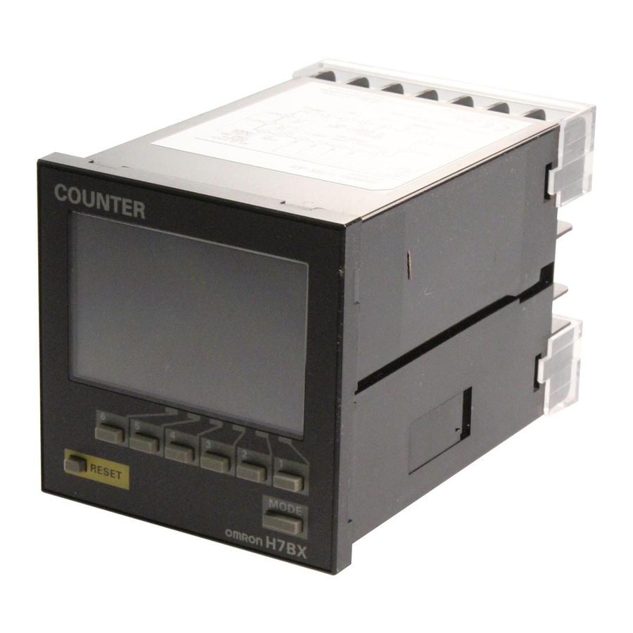
H7BX
Digital Counter
ENGLISH
INSTRUCTION MANUAL
Thank you for purchasing this OMRON product. To ensure
safety and correct use, read this English Instruction
Manual and be sure you sufficiently understand the
information provided before attempting to use the H7BX.
Keep this Instruction Sheet close at hand and use it for
reference during operation.
OMRON Corporation
© OMRON Corporation 2007 All Rights Reserved.
1651863-2A
For details, refer to the H7BX Digital Counter Datasheet (Cat. No. M077).
Safety Precautions
Definition of Precautionary Information
Indicates a potentially hazardous situation which,
Caution
if not avoided, may result in minor or moderate injury
or in property damage.
Precautions
Caution
Minor injury due to electric shock may occasionally occur. Do
not touch any of the terminals while power is being supplied.
Fire may occasionally occur. Tighten the terminal screws to
a torque of 0.5 to 0.6 N ⋅ m (4.4 to 5.3 in-lb).
Minor injury due to explosion may occasionally occur. Do not
use the Counter where subject to flammable or explosive gas.
If the output relay is used beyond its life expectancy, its
contacts may become fused or there may be a risk of fire.
Use the output relay within its rated load and electrical life
expectancy. The life expectancy of the output relay varies
considerably according to its usage.
Minor electric shock, fire, or malfunction may occasionally
occur. Never attempt to disassemble, modify, or repair the
Counter or touch any of the internal parts.
Precautions for Safe Use
Operating Environment
• The Counter is intended for indoor use only. Do not use the Counter
outdoors or in any of the following locations.
• Locations subject to sudden or extreme changes in temperature.
• Locations where high humidity may result in condensation.
• Locations subject to direct sunlight.
• Locations subject to corrosive gas.
• Locations subject to excessive dust or dirt.
• This is a class A product (for industrial environments). In residential
areas, it may cause radio interference, in which case the user may be
required to take adequate measures to reduce interference.
• Use the Counter within the specified ratings for operating temperature
and humidity. Temperature rise may shorten the service life of the Counter
if it is used near a power supply or other heat-generating objects.
• Use the Counter within the specified ratings for vibrations, shock, and
splashing water.
• The Counter is not oil resistant. Do not use it in locations subject to oil.
• Install the Counter well away from any sources of excessive static
electricity, such as pipes transporting molding materials, powders, or
liquids.
• Store the Counter within the specified ratings. If the Counter has been
stored at temperatures of −10°C or lower, let it stand for 3 hours or longer
at room temperature before turning ON the power supply.
Power Supply
• Maintain voltage fluctuations in the power supply within the specified
range.
• Internal elements may be destroyed if a voltage outside the rated voltage
is applied.
• When the power is turned ON, an inrush current will flow for a short time
(approx. @.@ A for @.@ ms). Depending on the power supply capacity,
operation may not start. Be sure to use a power supply with a sufficient
capacity.
• Use a commercial power supply as the AC power supply for the Counter.
Using an inverter output with an output frequency of 50/60 Hz as the
power supply may cause the Counter to produce smoke or become
damaged by burning.
• Use a switch, relay, or other device with contacts so that the rated power
supply voltage will be reached within 2 s. If the power supply voltage is
not reached quickly enough, the outputs may malfunction.
• Use a switch, relay, or other device with contacts to turn the power supply
OFF instantaneously. Outputs may malfunction and memory errors may
occur if the power supply voltage is decreased gradually.
Installation and Wiring
• To mount the Counter to a panel, attach the two supplied brackets to the
left and right sides of the Counter, and securely tighten the knurled
screws on the brackets by hand, maintaining a balance between them.
Damage may result if the knurled screws are excessively tightened
with pliers or other tools.
• Be sure to wire the terminals correctly.
• Up to two wires of the same size and type can be inserted into a single
terminal.
• Do not connect more than two crimp terminals to each Counter terminal.
• Use the specified wires for wiring.
Applicable wire: AWG 24 to AWG 18
(equal to a cross-sectional area of 0.20 to 0.82 mm
Solid wire or twisted wire (copper)
• Separate the Counter, the devices that generate input signals, and input
signal wires from any potential sources of noise, such as high-voltage
lines.
Handling
• Do not use organic solvents (such as paint thinner or benzine),
strong alkaline, or strong acids because they will damage the
external finish.
• Approximately 14 V will be output to the input terminals when the
Counter is used with the key protection input terminals and no-voltage
input (NPN input) are used. To prevent charging accidents, connect
a diode to the power supply circuit of input devices if input devices are
used with a power supply of less than 14 V.
• Do not connect loads that exceed the rated output current. The
output elements may be destroyed, possibly resulting in short-circuit
or open-circuit faults.
• When using heaters, be sure to use a thermal switch for the load circuit.
• Always connect a diode to protect against counter electromotive
force when using an inductive load. Counter electromotive force may
destroy output elements, possibly resulting in short-circuit or open-
circuit faults.
• Install a switch or circuit breaker that allows the operator to immedia-
tely turn OFF the power, and label it to clearly indicate its function.
• Check that the display (backlight and LCD) is operating normally.
Some operating environments may accelerate deterioration of the
indicators, LCD, and resin components and cause display malfunctions.
Periodically inspect and replace parts.
Precautions for Correct Use
• Inrush current generated by turning ON or OFF the power supply may
deteriorate contacts in the power supply circuit. Turn ON or OFF using
a device with a rated current of 10 A or higher.
• Inputs signals may be accepted, not accepted, or unstable for the
following times when the power supply is turned ON or OFF.
Set the system to allow leeway in the timing of input signals.
ON
Power
OFF
supply
0 to 90 ms
5 ms
0 to 1 s
200 ms
Un-
Input
Impossible
Possible
Unstable
stable
• This Counter always compares the count value with the set value. Thus,
if you change the set value during operation, please remember that the
output will turn ON when the set value becomes equal to the count
value.
• With the factory setting, the output will turn ON when power is supplied
to the Counter because the set value and count value are both zero.
During resetting, however, the output stays OFF.
• EEPROM is used as memory when the power is interrupted. The write
life of the EEPROM is 100,000 writes. The EEPROM is written when
settings are changed, or the power is tuned OFF.
• Water resistance will be lost if the front sheet is peeled off or torn.
Do not use the Counter if the front sheet is missing or torn.
• Abide by all local ordinances and regulations when disposing of
the Counter.
Conformance to EN/IEC Standards
Power supply, input, and output terminals have basic insulation between
them. When double insulation is required, apply supplemental insulation
defined in IEC 60664 that is suitable for the maximum operating voltage
with clearances or solid insulation.
Specifications
H7BX-A(W): 100 to 240 VAC (50/60 Hz), 9.6 VA max.
Power supply voltage/
H7BX-A(W)D1: 24 VAC (50/60 Hz), 8 VA max.
Power consumption
12 to 24 VDC, 5.3 W max.
85 to 110 % of the rated voltage
Operating voltage range
(90 to 110 % in the case of DC12-24 V)
−10 to 55°C (with no freezing)
Ambient temperature
Ambient humidity
25 to 85% (with no condensation)
−25 to 65°C (with no freezing)
Storage temperature
Altitude
2,000 m max.
10 to 55 Hz, single amplitude: 0.5 mm, 4 sweeps each
Vibration resistance
in X, Y, and Z directions (5 octave/min)
2
Shock resistance
98 m/s
3 times each in X, Y and Z directions
Recommended external fuse
T2A, 250 VAC, time-lag, low-breaking capacity
Installation environment
Over-voltage category II, pollution degree 2 (as per IEC61010-1)
Relay output
250 VAC, 3 A (resistive load), 30 VDC, 3 A (resistive load)
Control
Transistor
output
output
Relay durability
Electrical: 100,000 times, Mechanical: 10,000,000 times
External power supply
12 VDC, 100 mA (See note.)
Degree of protection
IP54 (front section only)
Note:
Reduce the load current as shown in the
diagram on the right according to the
power supply voltage if a DC power
supply is used for models specified for
24 VAC/12 to 24 VDC.
Step1
This Counter includes multiple counting functions. If the Counter is to be
used with a configuration other than the factory-set configuration given in
the table on the right, enter the Configuration Selection Mode shown in the
diagram on the right, and set the configuration to match the application.
Step2
The settings in
can be made before making the settings
in
Step1
.
Setting for Counter Operation (1-stage/2-stage Counter, Total and Preset Counter, Batch Counter, Dual Counter)
Step2
Basic parameters can be set using the DIP switch.
Perform
Step3
if the desired input or output mode is not given in the
following table or if all parameters will be set by using the front-panel keys.
Item
OFF
ON
Note: All of the pins are factory-set to OFF.
DIP switch settings
1
Disabled
Enabled
enable/disable
2
Counting speed
30 Hz
5 kHz
3
Input mode
Up
Down
4
Refer to the table
Output mode
on the right.
5
6
One-shot output time
0.5 s
0.05 s
7
Reset input signal width
20 ms
1 ms
8
NPN/PNP Input Mode
NPN
PNP
Step3
Parameters that cannot be set with the DIP switch are set with the
front-panel keys.
1. Switch the operation mode to configuration selection mode.
Power ON
Run mode
MODE
2. Set the parameters.
If pin 1 of the DIP switch is turned ON, the shaded setting items will not be displayed.
cntm
Input mode
(See note 1.)
up
MODE
outm
Output mode
n
MODE
otim
One-shot output
time (See note 2.)
0.50
MODE
cnts
Counting speed
30hz
MODE
iflt
Reset input
20ms
signal width
MODE
MODE
dp
Decimal point
------
position
2
)
MODE
pscl
Prescale value
1.000
MODE
imod
NPN/PNP Input
Mode
npn
MODE
colr
Present value
display color
red
selection
MODE
kypt
Key Protection
kp-1
Level
Displays and Settings in Run Mode
• 1-stage Counter
• 2-stage Counter
123456
Present value
Set value
234567
SET
• Total and preset counter
• Batch counter
123456
Present value
Set value
234567
SET
MODE
345678
Total count value
TOTAL
• Tachometer
• Dual Counter
Impossible
987654
Dual count value
994567
Dual count set value
SET
MODE
MODE
352423
CP1 present value
CP2 present value
635289
1 2
Front Panel Nomenclature
Indicators
1. Reset Indicator (Orange)
2. Key Protection Indicator (Orange)
3. Control Output Indicator (Orange)
OUT: One stage
OUT1, OUT2: Two stages
4. Present Value (Character height:
13.5 mm, Red or Green)
5. Set Value
(Character height: 9 mm, Green)
6. Total Indicator (Green)
7. Batch Indicator (Green)
8. Set Value 1, 2 Stage Indicator
(Green)
Operation Keys
9. Mode Key
10.Reset Key
11 Up Keys: 1 to 6
Counter and Panel Cutout Dimensions
Counter Dimensions
72
72
(Dimensions with Mounting Bracket and Terminal Cover Attached)
Note: The mounting panel thickness should be 1 to 5 mm.
100
Panel Cutout Dimensions
Load
current
Panel cutouts are as shown below.
(mA)
(according to DIN 43700)
20
0
10.8
15
Power supply voltage (VDC)
Operating Procedures
Power ON
Configuration
1
MODE +
Selection Mode
Run Mode
Hold down for
1 s min.
When pin 1 of the DIP switch is turned ON (enabled), the
status of the DIP switch pins (1 to 8) can be checked by
using keys 1 to 6 .
Precautions for Correct Use
• Be sure to turn OFF the power supply
before changing the DIP switch.
• Set pin 1 to ON (enabled) to set functions
using the DIP switch.
Pin 4
Pin 5
Output mode
• The DIP switch settings will be read
OFF
OFF
N
ON
OFF
F
when the power supply is turned ON.
OFF
ON
C
Make the switch settings before installing
ON
ON
K-1
the Counter and supplying power.
• Correctly set the DIP switch according
to the items to be counted (measured)
and check the settings by using the DIP
switch monitor.
Configuration
selection mode
Hold down for 3 s min.
Note: The characters displayed in reverse video are the default settings.
up
UP
Note:
down
DOWN
1. The following will be displayed when a dual counter is used.
ud-a
UP/DOWN A
ud-b
UP/DOWN B
calm
ud-c
Dual Count
UP/DOWN C
Calculating Mode
add
Refer to the table on the lower right.
2. The output time is displayed only when the output mode
is C, R, K-1, P, Q, A, or K-2.
The following will be displayed when a 2-stage counter
0.01 to
0.50
to 99.99 (s)
or batch counter is used.
When using a 2-stage counter:
30hz
30 Hz
otm2
5khz
5 kHz
0.01
MODE
20ms
20 ms
otm1
1 ms
1ms
hold
------
No decimal point
When using a batch counter:
-----. . . . . -
One digit after decimal point
----. . . . . --
Two digits after decimal point
---. . . . . ---
Three digits after decimal point
otm2
0.01
0.001 to
1.000
to 99.999
Output Modes
n
f
npn
NPN input (including two-wire sensor)
c
pnp
PNP input
r
k-1
Control output OFF
Control output ON
p
red
Red (fixed)
q
grn
Green (fixed)
r-g
Red
Green
a
g-r
Green
Red
k-2
Key protectionn level 1
d
kp-1
kp-2
Key protection level 2
l
kp-3
Key protection level 3
h
kp-4
Key protection level 4
kp-5
Key protection level 5
Key Protection Settings
When the key protection input is ON, it is possible to prevent setting
errors by prohibiting the use of certain operation keys by specifying the
key protection level in the Configuration Selection Mode.
123456
Present value
Changing mode
Switching display
Set value 1
Level
200000
(See note.)
SET1
KP-1
Not possible
MODE
KP-2
Not possible
123456
Present value
KP-3
Not possible
Set value 2
280000
SET2
KP-4
Not possible
KP-5
Not possible
18
Present value
Note: Changing from Run Mode to Configuration Selection Mode or Function Setting Mode.
Set value
24
SET
Self-diagnostic Function
MODE
Present
Set
613
Batch count value
value
value
Error
Batch count set
display
display
1000
BATCH
value
------
No
Present value
(See note 1.)
change
underflow
ffffff
Present value
No
2280. 00
(See note 1.)
change
overflow
Measurement
value
MODE
e1
Not lit
CPU error
Measurement
2280. 00
Memory error
value
e2
Not lit
(RAM)
2300. 00
Comparison
SET1
value 1
MODE
Memory error
e2
sum
Measurement
2280. 00
(EEPROM)
value
2000. 00
SET 2
Comparison
Note 1: Display flashes.
value 2
2: The tachometer will reset automatically.
• Do not connect unused terminals as relay terminals.
H7BX-A
1
2
4
3
6
5
7
8
11
Unused
9
10
Key
protection
M3.5 terminal screw
H7BX-AD1
(Effective length: 6 mm)
69 × 69
Panel
Unused
6
102
5 + panel thickness
Key
protection
100 min.
+0.7
68
−0
+0.7
68
−0
Package Contents
82 min.
• Counter
• This Instruction Sheet
• Two mounting brackets
• Terminal cover
Configuration Selection Mode
Select the configuration using
: Factory setting,
keys 1 to 6 .
Display
func
1cnt
1cnt
2cnt
tcnt
MODE
bcnt
dip
dcnt
DIP switch monitor
taco
off
Step2
Basic parameters can be set using the DIP switch.
Perform
Step3
Refer to the table on the left for DIP switch pin positions and precautions
for correct use.
Note: All of the pins are factory-set to OFF.
Item
DIP switch settings
1
enable/disable
2
Counting speed
3
Tachometer Output
Mode
4
5
Average
1
2
3
4
5
6
7
8
processing
6
DIP switch
7
Not used
8
NPN/PNP Input
Mode
Step3
Parameters that cannot be set with the DIP switch are set with the
front-panel keys.
1. Switch from Run Mode to Configuration Selection Mode.
Power ON
2. Set the parameters.
If pin 1 of the DIP switch is turned ON, the shaded setting items will not
be displayed.
totm
add
: CP1 + CP2
hilo
sub : CP1 − CP2
cnts
30hz
dp
------
One-shot output 2 time
pscl
1.000
One-shot output 1 time
a?g
* If the output time is 0.00, hold is displayed.
off
MODE
autz
One-shot output 2 time
99.9
stmr
N
0.0
F
C
imod
R
npn
K-1
P
Q
colr
A
red
K-2
D
L
kypt
H
kp-1
You must allow sufficient leeway in ratings and performance and provide
proper fail-safe and other safety measures when using the Unit in any of
the following applications. Be sure also to consult with your OMRON
Reset Key
Up/down Key
in Run Mode
representative before actually attempting any of these applications.
Possible
Possible
Possible
1. Applications under conditions or environments not specified in user
Possible
Not possible
Possible
manuals.
Possible
Possible
Not possible
2. Applications for nuclear reactor control, train facilities, aviation
Possible
Not possible
Not possible
facilities, motor ized vehicles, fur naces, medical equipment,
Not possible
Not possible
Not possible
amusement equipment, and safety equipment.
3. Applications strongly related to human life or property, particularly
those requiring safety.
Set
Output
Correction method
value
status
OMRON Corporation Control Device
after reset
Division H.Q.
Either press the Reset Key
No
No
Shiokoji Horikawa, Shimogyo-ku,
or turn ON the reset input.
change
change
Kyoto, 600-8530 Japan
Either press the Reset Key
No
Tel: (81)75-344-7109 Fax: (81)75-344-7149
No
or turn ON the reset input.
change
change
(See note 2.)
Regional Headquarters
Either press the Reset Key
No
OFF
or reset the power supply.
change
OMRON EUROPE B.V.
Wegalaan 67-69, NL-2132 JD Hoofddorp
No
Reset the power supply.
OFF
The Netherlands
change
Tel: (31)2356-81-300
Press the Reset Key to
Fax: (31)2356-81-388
return to the factory
0
OFF
settings.
Note:
Specifications subject to change without notice.
Printed in Japan
Terminal Arrangement
H7BX-AW
0 V
0 V
8
9
10 11 12 13 14
8
9
10 11 12 13 14
(−)
(+)
(−)
(+)
External power
External power
Unused
supply
supply
15
17
15
Unused
OUT1
OUT
OUT2
Key
16
18
16
protection
OUT2
OUT1
OUT
1
2
3
4
5
6
7
1
2
3
4
5
6
7
Unused
Unused
H7BX-AWD1
0 V
0 V
8
9
10 11 12 13 14
8
9
10 11 12 13 14
(−)
(+)
(−)
(+)
External power
External power
supply
Unused
supply
15
17
15
OUT1
Unused
OUT
OUT2
Key
16
18
16
protection
OUT
OUT2
OUT1
1
2
3
4
5
6
7
1
2
3
4
5
6
7
Unused
Unused
(−)
(+)
(−)
(+)
• Three DIP switch labels
(Only for model H7BX-AW@)
: Selectable, : Not selectable
H7BX-A
H7BX-AW
Configuration
H7BX-AD1
H7BX-AWD1
1-stage counter
2-stage counter
Total and preset counter
Batch counter
Dual counter
Tachometer
Using a Tachometer
if all parameters will be set by using the front-panel keys.
Tachometer
Pin 3
Pin 4
Output Mode
Upper and
OFF
ON
OFF
OFF
lower limit
Disabled
Enabled
ON
OFF
Area
OFF
ON
Upper limit
30 Hz
10 kHz
ON
ON
Lower limit
Refer to the table
on the right.
Average
Pin 5
Pin 6
processing
Refer to the table
on the right.
OFF
OFF
OFF
ON
OFF
2 times
---
---
OFF
ON
4 times
NPN
PNP
ON
ON
8 times
Configuration
Run Mode
Selection Mode
MODE
Hold down for 3 s min.
Note: The characters displayed in
reverse video are the default settings.
hilo
Upper and lower limit
Area
area
Tachometer
hihi
Upper limit
Output Mode
lolo
Lower limit
MODE
30hz
30 Hz
Counting speed
10khz 10 kHz
MODE
------
No decimal point
-----. . . . . -
One digit after decimal point
Decimal point
----. . . . . --
Two digits after decimal point
position
---. . . . . ---
Three digits after decimal point
MODE
Prescale value
0.001 to
1.000
to 99.999
MODE
off
No average processing
Average
2
Average of 2 measurements
processing
4
Average of 4 measurements
8
Average of 8 measurements
MODE
Auto-zero time
0.1 to
99.9
s
MODE
Startup time
0.0
to 99.9 s
MODE
npn
NPN input (including two-wire sensor)
NPN/PNP Input
pnp
Mode
PNP input
MODE
Control output OFF Control output ON
red
Present value
Red (fixed)
display color
grn
Green (fixed)
selection
r-g
Red
Green
g-r
Green
Red
MODE
kp-1
Key protection level 1
kp-2
Key protection level 2
Key Protection
kp-3
Key protection level 3
Level
kp-4
Key protection level 4
kp-5
Key protection level 5
SUITABILITY FOR USE
OMRON ELECTRONICS LLC
1 East Commerce Drive, Schaumburg,
IL 60173 U.S.A
Tel: (1)847-843-7900
Fax: (1)847-843-8568
OMRON ASIA PACIFIC PTE. LTD.
83 Clemenceau Avenue,
#11-01, UE Square,
Singapore 239920
Tel: (65)6835-3011
Fax: (65)6835-2711
OMRON (CHINA) CO., LTD.
Room 2211, Bank of China Tower,
200 Yin Cheng Zhong Road,
PuDong New Area, Shanghai,
200120 China
Tel: (86)21-5037-2222
17
18
17
18
Advertisement
Table of Contents

Related Manuals for Omron H7BX


Summary of Contents for Omron H7BX
- Page 1 T2A, 250 VAC, time-lag, low-breaking capacity Installation environment Over-voltage category II, pollution degree 2 (as per IEC61010-1) For details, refer to the H7BX Digital Counter Datasheet (Cat. No. M077). 69 × 69 Relay output 250 VAC, 3 A (resistive load), 30 VDC, 3 A (resistive load)
- Page 2 リ 出 出 セ セ セ セ 設置環境 過電圧カテゴリ Ⅱ、 汚染度2 (IEC61010-1による) 力 力 詳細については、 「 新商品ニュース 形H7BX」 ( SGTB-010) を ご覧く だ さい。 ッ ッ ッ ッ ト ト ト ト 69×69 リ レー出力 AC250V 3A (抵抗負荷) 、 DC30V 3A (抵抗負荷)...
Need help?
Do you have a question about the H7BX and is the answer not in the manual?
Questions and answers