Table of Contents
Advertisement
Quick Links
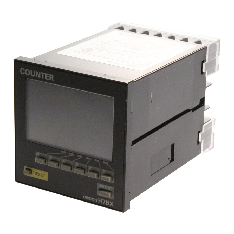
Multifunction Counter (DIN 72 × 72)
H7BX
DIN 72 × 72 mm Multifunction Counter with a
Bright, Easy-to-view, Negative Transmissive LCD.
• Highly visible display with backlit transmissive LCD.
• Selectable display color (red/green) enables checking output status at a
distance.
• Easy operation with a key for each digit.
• Perform all basic settings with a DIP switch.
• Provides a total and preset counter, batch counter, dual counter, twin
counter, and tachometer (See note.).
• Equipped with a Replacement Time Notification Function to be notified
in advance by predicting the service life.
• Equipped with a Memory Backup and H7AN Compatibility Function to
facilitate problem-free conversion from H7AN.
• Wide range of inputs accepted for NPN/PNP inputs (multi-inputs) and 2-
wire DC sensors.
• Complies with UL, CSA, and CE marking.
• Degree of protection: IP54 equivalent (front section only).
Note: The functions that can be selected depend on the model.
Ordering Information
List of Models
External power supply
Contact and
12 VDC
NPN transistor output
Accessories (Order Separately)
Name
Soft Cover
Hard Cover
Terminal Cover *
* Supplied with the H7BX.
Output type
Supply voltage
100 to 240 VAC
24 VAC/12 to 24 VDC
Model
Y92A-72F1
Y92A-72
Y92A-72T
For the most recent information on models that have been certified for
safety standards, refer to your OMRON website.
Refer to Safety Precautions on page 36.
1-stage
H7BX-A
H7BX-AD1
CSM_H7BX_DS_E_5_1
2-stage
H7BX-AW
H7BX-AWD1
1
Advertisement
Table of Contents

Related Manuals for Omron H7BX


Summary of Contents for Omron H7BX
- Page 1 For the most recent information on models that have been certified for • Wide range of inputs accepted for NPN/PNP inputs (multi-inputs) and 2- safety standards, refer to your OMRON website. wire DC sensors. • Complies with UL, CSA, and CE marking.
-
Page 2: Specifications
85% to 110% of rated supply voltage (90% to 110% at 12 VDC) range H7BX-A/AW: 9.6 VA max. (100 to 240 VAC) Power consumption H7BX-AD1/AWD1: 8 VA max. (24 VAC), 5.3 W max. (12 to 24 VDC) Mounting method Flush mounting External connections... -
Page 3: Applicable Standards
Dielectric (for models other than the H7BX-A@D1) strength 1,000 VAC, 50/60 Hz for 1 min (H7BX-A@D1) Between control output, power supply, and input circuit: 2,000 VAC, 50/60 Hz for 1 min Between non-continuous contacts: 1,000 VAC, 50/60 Hz for 1 min 30 VDC (cosφ=1) - Page 4 H7BX I/O Functions Using as a Counter *1 (1) All Modes Except for Dual Counter Mode and Twin Counter Mode • Reads count signals. • Increment, decrement, up/down (command, individual, or quadrature) inputs can be used. CP1, CP2 (2) Dual Counter Mode or Twin Counter Mode •...
-
Page 5: Terminal Arrangement
H7BX Connections Terminal Arrangement Confirm that the power supply meets specifications before using the H7BX. H7BX-A H7BX-AW 10 11 12 13 14 10 11 12 13 14 (−) (−) External power supply External power supply Unused. Unused. Unused. OUT1 OUT2... -
Page 6: Input Connections
Operates when the transistor turns ON. Operates when the transistor turns ON. Operates when the transistor turns ON. Note: When using the H7BX as a tachometer, do not use the CP2 input or total reset/reset 2 input. No-voltage Input Signal Levels Applicable Two-wire Sensors... - Page 7 67.6 × 67.6 Note: M3.5 terminal screws (effective length: 6 mm). Dimensions with Flush Mounting Adapter H7BX-A@@ (The flush mounting adapter is supplied with the H7BX.) Panel Cutouts Panel cutouts are as shown below M3.5 terminal screw (according to DIN 43700).
-
Page 8: Operating Procedures
10 to 12. Note: The default setting is for a 1-stage preset counter. (For models with a 2-stage setting, the default is a 2-stage preset counter.) Setting for Tachometer Operation (H7BX-AW@ only) ● Using Basic Settings Only Basic Settings... - Page 9 DIP switch. For details on the setting methods, refer to page 10 to 12. When performing these settings, always turn OFF pin 1(DIP switch setting) (disabled). Using the H7BX as a Total and Preset Counter, Batch Counter, Dual Counter, or Twin Counter The default setting is for a 1-stage preset Power ON counter.
-
Page 10: Setting Advanced Functions
H7BX When using the H7BX as a Total and Preset Counter, Batch Counter, Dual Counter, or Twin Counter, switch the configuration using the procedure on page 33. Setting Advanced Functions Settings that cannot be performed with the DIP switch are performed with the operation keys. - Page 11 ON: Output 1 (OUT1) = 3-4, 14-18 Output 2 (OUT2) = 5-6, 14-17 preset counter, batch counter, (The numbers are the terminals numbers.) and twin counter in H7BX-AW. · Set the key protect level with any of the Keys. kypt...
- Page 12 H7BX To previous From previous page page *9. Set each digit using the individual Keys. Procedure for Models Other than “-@W@” Models Output ON on-a Output ON count alarm count alarm 9999 set value/ set value (0 u (9999 u...
-
Page 13: Explanation Of Functions
If contacts are used for input signals, set the counting Green speed to 30 Hz. Processing to eliminate chattering is performed for Green this setting. * When the H7BX using as a 2-stage counter, this is the status of output 2. - Page 14 This function enables the set value (deviation with respect to set value 2). same operation when the H7AN is replaced with the H7BX. The forecast output (output 1) turns ON when the present value •...
-
Page 15: Operation In Run Mode
H7BX Operation in Run Mode I/O Functions for Counter Operation • Set values for each digit as required using the Keys. 1-stage Preset Counter Total and Preset Counter Dual Counter Present value Dual count value Present value Set value Dual count... - Page 16 H7BX Input Modes and Present Value (See note 1.) UP (Increment) Mode DOWN (Decrement) Mode CP1: Count input; CP2: Prohibit input CP1: Count input; CP2: Prohibit input Prohibit Prohibit n−1 n−2 Present Present n−3 value value n−4 n−5 must be greater than the minimum signal width. (See note 2.) must be greater than the minimum signal width.
- Page 17 H7BX UP/DOWN A: Command Input Mode UP/DOWN B: Individual Input Mode Present Present value value must be greater than the minimum signal width. (See note 2.) UP/DOWN D Command Input Mode UP/DOWN C: Quadrature Input Mode B B B B...
- Page 18 H7BX Input/Output Mode Settings I/O Functions for Counter Operation If a 1-stage model or 2-stage model is used as twin counter, the operation for output 2 will be performed. When using a 2-stage model as a 1-stage preset counter, total and preset counter, or dual counter, OUT1 and OUT2 turn ON and OFF simultaneously.
- Page 19 H7BX One-shot output from OUT1 (The one-shot output time can be set in the range 0.01 to 99.99s.) Self-holding Self-holding One-shot output output output from OUT2 Operation after count Input mode completion DOWN Reset/ Reset/ reset 1 reset 1 999999...
- Page 20 H7BX One-shot output from OUT1 (The one-shot output time can be set in the range 0.01 to 99.99s.) Self-holding Self-holding One-shot output output output from OUT2 Operation after count Input mode completion DOWN Reset/ Reset/ reset 1 reset 1 999999...
- Page 21 H7BX One-shot output from OUT1 (The one-shot output time can be set in the range 0.01 to 99.99s.) Self-holding Self-holding One-shot output output output from OUT2 Operation after count Input mode completion DOWN Reset/ Reset/ reset 1 reset 1 999999...
- Page 22 H7BX (The one-shot output time can be set in the range 0.01 to 99.99s.) Self-holding Instanta- One-shot output neous output (equals) output Input mode Operation after count completion UP/DOWN A, B, C Reset/reset 1 999999 Set value 2 The display continues to increase/...
- Page 23 Batch Counter Operation The H7BX has a batch counter separate from the 1-stage preset counter for counting the number of times the count has been completed. Reset 1 • The batch counter continues after count completion.
- Page 24 H7BX Twin Counter Operation Two independent counters are built in. Counter 1 Counter 2 Counter input Reset input Reset 1 Reset 2 Counter 1 display Counter 2 display Counter 1 present value Counter 2 present value Present value display and...
- Page 25 H7BX Operating Procedures (Tachometer Function) (H7BX-AW@ only) Switching from Counter to Tachometer The H7BX is factory-set to the 2-stage counter configuration. To switch to the tachometer Power ON configuration, use the procedure shown on the right. For details, refer to page 33.
- Page 26 H7BX When the H7BX using as a tachometer, switch to the tachometer configuration using the procedure given on page 33. Settings for Advanced Functions Settings that cannot be performed with the DIP switch are performed with the operation keys. Power ON For details on operations in run mode, refer to page 31.
- Page 27 ON: Output 1 (OUT1) = 3-4, 14-18 Output 2 (OUT2) = 5-6, 14-17 preset counter, batch counter, (The numbers are the terminals numbers.) and twin counter in H7BX-AW. · Set the key protect level with any of the Keys. kypt...
- Page 28 H7BX To previous From previous page page Output 1 (OUT1) on1a ON count 9999 alarm set value (ON1A) (0 × (9999 × 1000 times) 1000 times) Output 2 (OUT2) on2a ON count 9999 alarm set value (ON2A) (0 × (9999 ×...
- Page 29 • Auto-zero Time (aVto0) • Prescale Value (pscl) It is possible to set the H7BX so that if there is no pulse for a certain time the display is force-set to 0. This time is called the auto-zero time. It is possible to display the rate of rotation or the speed of a device or...
- Page 30 1 is OFF and in red when control output 1 is ON. • Output Allocation (Settings applicable to only H7BX-AW) (otst) Set the allocation of outputs 1 and 2 (OUT1 and OUT2). If output...
- Page 31 H7BX Operation in Run Mode • Set the number for each digit with the Keys. • Measurement Value Measurement value Displays the currently measured value. • OUT1/OUT2 Set Value Set OUT1 set value and OUT2 set value. The Measurement value *2...
- Page 32 H7BX Output Mode Settings (Upper-limit) OUT2 set value Measurement value Upper and (Lower-limit) ON condition for OUT1: Measurement value ≤ OUT1 set value lower limit OUT1 set value ON condition for OUT2: Measurement value ≥ OUT2 set value (HI-LO) OUT1 OUT2 OUT1 set value ≤...
- Page 33 Select which H7BX configuration to use (i.e., preset counter, total and preset counter, batch counter, dual counter, twin Counter, or tachometer) in the configuration selection mode. The H7BX is also equipped with a DIP switch monitor function, a convenient function that enables the settings of the DIP switch pins to be confirmed using the front display.
- Page 34 (KP-1 to KP-5). The key protect indicator is lit while the key-protect switch is set to ON. Confirm the ON/OFF status of the key protect switch after the H7BX is mounted to the panel. Key protection is enable by short-circuited key protection terminals.
-
Page 35: Self-Diagnostic Function
Set the alarm value for the output ON count. The H7BX is equipped with a function for notifying the replacement The limit can be set between 0×1000 (0 times) and 9999×1000 time by the cumulative run time and ON count of the relay contact. -
Page 36: Safety Precautions
• Always connect a diode to protect against counter electromotive splashing water. force when using an inductive load. H7BX electromotive force may • The H7BX is not oil resistant. Do not use it in locations subject to destroy output elements, possibly resulting in short-circuit or oil. - Page 37 • Water resistance will be lost if the front sheet is peeled off or torn. Do not use the H7BX if the front sheet is missing or torn. • Abide by all local ordinances and regulations when disposing of the H7BX.
-
Page 38: Terms And Conditions Agreement
(a) Exclusive Warranty. Omron’s exclusive warranty is that the Products will be free from defects in materials and workmanship for a period of twelve months from the date of sale by Omron (or such other period expressed in writing by Omron). Omron disclaims all other warranties, express or implied.
Need help?
Do you have a question about the H7BX and is the answer not in the manual?
Questions and answers