
Related Manuals for Omron CJ1W-CTL41-E


Summary of Contents for Omron CJ1W-CTL41-E
- Page 1 Cat. No. W02E-EN-01 SYSMAC CJ-series CJ1W-CTL41-E 4-Channel Counter Unit OPERATION MANUAL...
- Page 2 SYSMAC CJ-series CJ1W-CTL41-E 4-Channel Counter Unit Operation Manual Produced September 2004...
- Page 4 OMRON Product References All OMRON products are capitalised in this manual. The word “Unit” is also capitalised when it refers to an OMRON product, regardless of whether or not it appears in the proper name of the product.
-
Page 6: Table Of Contents
TABLE OF CONTENTS PRECAUTIONS ........Intended Audience ............General Precautions . - Page 7 Application Restrictions ........... . Comparison between CJ1W-CTL41-E and other Counter Units .....
- Page 8 About this Manual: This manual describes the installation and operation of the CJ1W-CTL41-E Counter Unit and includes the sections described below. Please read this manual carefully and be sure you understand the information provided before attempting to install or operate the CJ1W-CTL41-E Counter Unit.
- Page 9 viii...
- Page 10 PRECAUTIONS This section provides general precautions for using the Programmable Controller (PLC) and the Counter Unit. The information contained in this section is important for the safe and reliable application of the Counter Unit. You must read this section and understand the information contained before attempting to set up or operate a Counter Unit and PLC system.
-
Page 11: Intended Audience
It is extremely important that a PLC and all PLC Units be used for the specified purpose and under the specified conditions, especially in applications that can directly or indirectly affect human life. You must consult with your OMRON repre- sentative before applying a PLC system to the above mentioned applications. -
Page 12: Operating Environment Precautions
Operating Environment Precautions !WARNING Do not attempt to take any Unit apart while the power is being supplied. Doing so may result in electric shock. !WARNING Do not touch any of the terminals or terminal blocks while the power is being supplied. -
Page 13: Application Precautions
Application Precautions Application Precautions Observe the following precautions when using the Counter Unit or the PLC. !WARNING Failure to comply with the following precautions could lead to serious or possibly fatal injury. Always follow these precautions. • Always ground the system with 100 Ω or less when installing the system, to protect against electrical shock. - Page 14 Application Precautions • Install the Units properly as specified in the operation manuals. Improper !Caution installation of the Units may result in malfunction. • Be sure that all the mounting screws, terminal screws, and cable connector screws are tightened to the torque specified in the relevant manuals. Incorrect tightening torque may result in malfunction.
- Page 15 Application Precautions vided with the CPU Unit to the right most Unit. CJ-series PLCs will not operate properly if the end cover is not attached.
-
Page 16: Ec Directives
Concepts EMC Directives OMRON devices that comply with EC Directives also conform to the related EMC standards so that they can be more easily built into other devices or the overall machine. The actual products have been checked for conformity to EMC stand- ards (see the following note). - Page 17 Section Note Applicable EMS (Electromagnetic Susceptibility) and EMI (Electromagnetic Inter- ference standards in the EMC (Electromagnetic Compatibility) standards are as follows: Unit CJ1W-CTL41-E EN 61000-6-2:2001 EN 61000-6-4:2001 6-3-3 Conformance to EC Directives Units that meet EC directives also meet the common emission standard (EN61000-6-4).
-
Page 18: Introduction
SECTION 1 Introduction This section gives specifications of the CJ1W-CTL41-E and a brief description of the functions and features of the Unit and the areas of application. Features and Functions ............. . . 2 Basic Configuration . -
Page 19: Features And Functions
Features and Functions CJ1W-CTL41-E The CJ1W-CTL41-E, a Special I/O Unit for CJ-series PLC-systems, is a freely configurable Counter Unit. Depending on the requirements of your applica- tion, the specific behaviour of the Unit can be adjusted by changing the con- figuration settings. - Page 20 Features and Functions Section 1-1 ware Outputs. An Output is turned ON when the Counter is in the correspond- ing Range. In Comparison Mode a configurable number of up to 8 Comparison Values can be applied to individual Counters. Depending on the direction of counting, an Output can be set or reset (configurable) on reaching the Comparison Value.
-
Page 21: Basic Configuration
Proximity Sensor Other Pulse Generators Mounting Restrictions The CJ1W-CTL41-E Counter Unit is a Special I/O Unit belonging to the CJ Series. A CJ1W-CTL41-E Counter Unit can be mounted to either a CJ CPU Rack or CJ Expansion Rack. Note 1. In case of a CJ1-H CPU Unit, the Counter Unit must be in one of the five... -
Page 22: Specifications And Characteristics
Special I/O Unit (CIO) Area (refer to section 4-2-3 CIO-Memory Mapping). 3. For a CJ1W-CTL41-E Special I/O Unit the same space as for 4 Units in the Special I/O Unit DM Area are reserved. However, only the first 90 words are used to make the DM-settings. -
Page 23: Functional Specifications
1. A CJ1G-CPU@@H, CJ1H-CPU@@H or CJ1M-CPU@@ CPU Unit must be used. The older CJ1G-CPU@@ CPU Units (without H suffix) do not sup- port external interrupt tasks. To activate external interrupt tasks in a CJ1G- H/ CJ1H-H CPU Unit, the CJ1W-CTL41-E Counter Unit must be in one of... -
Page 24: Input Specifications
CPU Unit. For CJ1M CPU Units, the CJ1W-CTL41-E Counter Unit must be in one of the three posi- tions immediately to the right of the CJ1M CPU Unit. No external interrupt tasks can be activated if the Unit is in any other position (i.e., 6th Unit po-... - Page 25 Specifications and Characteristics Section 1-3 Counter Inputs A, B and Z 24V input signals (via Input Terminal Block) RS-422 Line Driver signals Counter inputs A and B Counter inputs A and B Input pulses with a duty factor of 50% Input pulses with a duty factor of 50% Relationship between A and B phases with phase Relationship between A and B phases with phase...
-
Page 26: Quick Start Up Reference Guide
Start/Stop Reset Exchanging data with CPU The diagram below shows the functions the Unit provides to exchange data with the CPU (refer to section SECTION 4 Exchanging Data with CPU). CJ1W-CTL41-E CJ-series CPU Unit IOWR IORD Interrupts Unit Output Pattern... -
Page 27: Configuring The Counter Unit
Hysteresis mechanism is available to control the Outputs. Refer to section 3-5 Output Control. Indirect Addressing for The CJ1W-CTL41-E Counter Unit allocates 90 DM-words in the Special I/O Circular and Linear Unit DM-Area and a block of 34 CIO-words in the Special I/O Unit Area of the Counters PLC. -
Page 28: Operating Procedure Guidelines
Ranges or Comparison Values then it is also possible to use the work- words of the Special I/O Unit DM-Area to store the Range or Comparison Data (287 work-words for the CJ1W-CTL41-E are available). Therefore, at the end of every block with Counter Specific Settings, you can specify an Indirect Address. - Page 29 Operating Procedure Guidelines Section 1-5 3. Turn ON the Power to the PLC. Power ON 4. Create the I/O table. The I/O table can be created by using CX-Program- mer Support Software or a Programming Console. CX-Programmer Programming Console Unit Configuration After the I/O table is created in step 4, you have to configure the Unit by mak- ing the appropriate DM-settings.
-
Page 30: Application Areas
Counter Values. Application areas include: • Packaging and Sorting plants • Dosing or proportioning plants • Process Industry Typical applications in which the CJ1W-CTL41-E can be used: • (CAM)-Positioning • Position Monitoring • Length Measurement • Flow Control... -
Page 32: Components, Installation And Wiring
This section provides details of the components, switch settings and other information required to install and operate CJ1W-CTL41-E Counter Units. Components and Switch Settings ........ -
Page 33: Components And Switch Settings
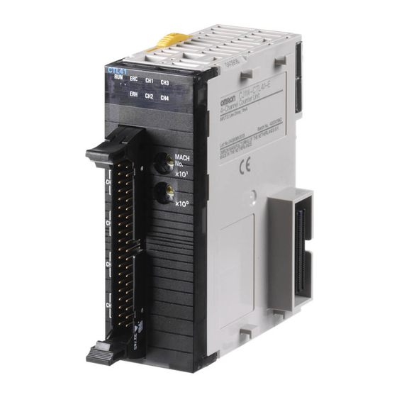
Components and Switch Settings Section 2-1 Components and Switch Settings 2-1-1 Components Front and Side View 83.6 CTL41 Indicators Machine Number Switch Units in mm 2-1-2 Indicators CTL41 The indicators on the LED-display show the operating status of the Unit. The fol- lowing table shows the meaning of the indicators. -
Page 34: Machine Number Switch
Components and Switch Settings Section 2-1 Colour State Description CPU Unit has operational failure. (For a list of all the errors that can occur at the CPU Unit see 5-1 Error Indicators) CPU Unit has no operational failure. Yellow Counter 1 is counting, i.e. the corresponding counting gate is enabled and at least one pulse has been detected. - Page 35 Area (CIO 2000 to CIO 2959 and DM 20000 to DM 29599) are allocated to the Counter Unit. The CJ1W-CTL41-E Unit occupies 4 Special I/O Unit Areas, i.e. the next Special I/O Unit Machine Number must at least be set to this Unit’s Machine Number plus 4.
-
Page 36: Installation
Installation 2-2-1 Installation Precautions When installing the CJ1W-CTL41-E Counter Unit on the PLC system, observe the following handling precautions • Always turn OFF the power supply to the PLC before mounting or dismount- ing a Unit or connecting or disconnecting cables. - Page 37 Installation Section 2-2 2. Slide the yellow sliders on the top and bottom of the Units until they click into place, firmly locking the Units together. Slide the sliders toward the back until they click into place. Slider PA20 5R Lock POWE R SYSMA C...
-
Page 38: Wiring
• RS-422 Line Driver, either directly connected to the connector on the front of the Unit or through a separate Input Terminal Block, e.g. the OMRON XW2G- 40G7-E or XW2D-40G6. • 24 Vdc signals from NPN- or PNP Drivers, only through the separate... -
Page 39: Connector Wiring Methods
Be sure that all the connectors are wired correctly and properly connected to the Counter Unit, to prevent the Unit from malfunctioning. To wire the CJ1W-CTL41-E in order to connect the external signals three methods are available: 1. Directly connecting the wires and cables to an external connector. Recom- mended connectors are 40-pin MIL-C-83503 (or DIN 41651 or IEC 60603-1) compatible 40-pole connectors. -
Page 40: Important Wiring Considerations
• XW2Z-300K (3 m) • XW2Z-500K (5 m) The next figure shows how to use the Terminal Block Unit in a typical configuration together with the CJ1W-CTL41-E Counter: CTL41 Refer to section Appendix A Using Input Terminal Block Units for information on the numbering of the screw-terminals. -
Page 41: Internal Circuitry
Wiring Section 2-3 2-3-4 Internal Circuitry Counter Input Circuitry The figure below shows the internal input circuitry for all three input signals for each of the four Counter channels. Phase A Phase B Phase Z 2-3-5 Counter Input Configuration The following example illustrates how to wire the Counter Inputs in a typical con- figuration according to the output-driver of the encoder or proximity switch being used. - Page 42 Wiring Section 2-3 Line Driver (RS422) CJ1W-CTL41-E Counter Un Terminals: Black: Phase A+ 1 (Phase A, LD+) Black/red: Phase A- 2 (Phase A, LD-) Encoder White: Phase B+ 3 (Phase B, LD+) White/red: Phase B- 4 (Phase B, LD-) Orange: Phase Z+...
-
Page 44: Operation And Configuration
SECTION 3 Operation and Configuration This section describes how to configure the CJ1W-CTL41-E Counter Unit and how to operate the Unit according to the specific requirements of your application. Overview........... . . -
Page 45: Overview
Section 2-2 Installation and Section 2-3 Wiring, you have to configure the Unit by making DM-settings. In this section you will learn how to configure the CJ1W-CTL41-E Counter Unit in order to adjust the behaviour of the Unit according to the specific requirements of your application (refer to section Section 1-4 Quick Start Up Reference Guide for an overview of the configuration items for every Counter). -
Page 46: Counter Types
Counter Types Section 3-2 Counter Types Every single Counter of the Counter Unit can be set independently to one of the following Counter Types: • Circular Counter (refer to section Section 3-2-1 Circular Counter) • Linear Counter (refer to section Section 3-2-2 Linear Counter) Each Counter can be configured Circular or Linear Counter by giving the corre- sponding word in DM the appropriate setting: CNT1:... -
Page 47: Circular Counter
Counter Types Section 3-2 3-2-1 Circular Counter Note All of the functions listed in Section 1-3-2 Functional Specifications can be used if a Circular Counter is configured. Configuring Circular Counters 15 14 13 12 11 10 9 CNT1: CNT2: CNT3: CNT4: m+10 m+30... -
Page 48: Linear Counter
Counter Types Section 3-2 3-2-2 Linear Counter Note All of the functions listed in Section 1-3-2 Functional Specifications can be used if a Linear Counter is configured. Configuring Linear Counters 15 14 13 12 11 10 9 CNT1: CNT2: CNT3: CNT4: m+10 m+30... - Page 49 Counter Types Section 3-2 Configuring Error-Code To configure Overflow/Underflow Error Code Generation for a Linear Counter refer Generation to section the following: 15 14 13 12 11 10 9 CNT1: CNT2: CNT3: CNT4: m+12 m+52 m+72 Overflow/Underflow Error-Code generation: 0 = No Error-Code generation 1 = Error-Code generation Reporting Overflow and An Overflow or Underflow of a Linear Counter is reported in the corresponding bits...
-
Page 50: Input Signal Types
Input Signal Types Section 3-3 Input Signal Types The type of input you require for your application is selected by means of four bits in the Signal Type Word in DM. For every Counter the Signal Type can be selected individually. -
Page 51: Up & Down
Input Signal Types Section 3-3 Multiplication x2 To increase the resolution of the incremental encoder the Counter can be config- ured for Multiplication by 2. If the Counter is up-counting (signal A leads to signal B) pulses are taken into account by the Counter on the rising- and falling edges of signal A. -
Page 52: Pulse & Direction
Input Signal Types Section 3-3 3-3-3 Pulse & Direction In this configuration, count pulses are applied to input A. The direction of counting is controlled by the level of the signal applied to input B. If input B is high, the Counter increments on the rising edges of input A. -
Page 53: Controlling A Counter
Controlling a Counter Section 3-4 Controlling a Counter Each Counter Input contains a gate through which the counting function can be enabled or disabled. When disabled, the gate will block incoming counter signals. The Gate of a Counter can be enabled and disabled by using the “Open Gate Bit” and “Close Gate Bit”... - Page 54 Controlling a Counter Section 3-4 15 14 13 12 11 10 9 CNT1: CNT2: CNT3 CNT4: n+10 Software Reset Bit: 0 1 = Reset Counter Z-Input Reset Enable Bit: 0 = Reset by Z-input disabled 1 = Reset by Z-input enabled Capture Function The Unit is equipped with a Capture Register for every Counter, which will contain an actual Counter Value captured at a user defined moment in time.
-
Page 55: Output Control
Output Control Section 3-5 Counting Direction For every Counter the (up or down) counting direction is indicated and can be used in the Ladder Program. 15 14 13 12 11 10 9 CNT1: CNT2: CNT3: CNT4: n+21 n+25 n+29 n+33 Gate Open/Closed: 0 = Gate Closed 1 = Gate Open... - Page 56 Output Control Section 3-5 Unit Output Pattern In both Range and Comparison Mode the 32 Outputs of the Unit are represented by the Unit Output Pattern. The Unit uses the Unit Output Pattern internally to con- trol the Outputs. The Unit Output Pattern consists of 32 internal Outputs Unit Output Pattern: 31 30 29 16 15 14...
-
Page 57: Range Mode
Output Control Section 3-5 3-5-1 Range Mode If the Unit is configured to control the Outputs in Range Mode, this Mode can be applied to Circular Counters or Linear Counters (refer to section Section 3-2-1 Cir- cular Counter and Section 3-2-2 Linear Counter for more information). Example Range Mode with Linear Counter Minimum Count Limit Maximum Count Limit... - Page 58 Output Control Section 3-5 Example Range Mode with Circular Counter Range 2 Maximum Count Limit 4,294,967,295 (=00000000 ) (= FFFFFFFF Range 1 Rollover Range 0 Range 3 Counter Value Range Lower Range Limit Upper Range Limit Output ON 60,000 80,500 45,000 1, 3 37,000,000...
- Page 59 Output Control Section 3-5 3-5-1-1 Range Mode Overview The following figure gives an overview on configuring Counters in Range Mode. Range 0 Counter 1 Upper Range Limit Output Pattern Lower Range Limit Output Pattern Range 3 Upper Range Limit Output Pattern Lower Range Limit Range 0 Counter 2...
- Page 60 Output Control Section 3-5 3-5-1-2 Configuration and operation in Range Mode Specifying Range-Data In Range Mode every Counter can be assigned up to a maximum of 4 Ranges. The Data of every Range is contained by 3 double words: • Lower Range Limit, specifying the Lower Limit of the Range •...
- Page 61 Counter comparisons for all counters. Set the Range Data considering that comparisons are stopped by execution of IOWR/IORD-instructions. Refer to section Section Appendix D Comparison between CJ1W-CTL41-E and other Counter Units for information on execution times for IOWR/IORD- instructions.
- Page 62 Output Control Section 3-5 A Range becomes active if: Lower Range Limit ≤ Counter Value ≤ Upper Range Reflecting Active / Not Active Ranges Limit. Whether or not a Range is active is reflected in CIO for each Counter. 15 14 13 12 11 10 9 CNT1: CNT2: CNT3...
-
Page 63: Comparison Mode
Output Control Section 3-5 Note The Counter Output Patterns of Counters which are configured to use no (i.e. zero) Ranges, are ignored in the AND-calculation of the Unit Output Pattern. Like this, Counters that you do not want to use, do not influence the AND-calculation of the Unit Output Pattern. - Page 64 Output Control Section 3-5 CV is crossed in the positive counting direction (+CV crossing) or negative count- ing direction (-CV crossing), one or multiple Outputs can be Set (S) or Reset (R). For example Output 0 is Set on crossing CV5 in the positive counting direction and Reset on crossing CV7 in the negative counting direction.
- Page 65 Output Control Section 3-5 3-5-2-1 Comparison Mode Overview The following figure gives an overview on configuring Counters in Comparison Mode. Counter 1 +Set Pattern CV0 +Reset Pattern CV0 Comparison Value 0 -Set Pattern CV0 -Reset Pattern CV0 +Set Pattern CV7 +Reset Pattern CV7 Comparison Value 7 -Set Pattern CV7...
- Page 66 Output Control Section 3-5 3-5-2-2 Configuration and operation in Comparison Mode Specifying Comparison- In Comparison Mode every Counter can be assigned up to a maximum of 8 Com- Data parison Values. The Data of every Comparison Value (CV-Data) is contained by 5 double words: –...
- Page 67 Comparison Result is refreshed using the new Comparison Data and the current Counter Value, which means the result of the comparison during the stoppage is not reflected. Refer to section Section Appendix D Comparison between CJ1W-CTL41-E and other Counter Units for information on execution times for IOWR/IORD-instruc- tions.
- Page 68 Output Control Section 3-5 5. In case for a CV both a Set and a Reset in one and the same counting direc- tion for a specific Output are defined, the Reset has priority. 6. The output can be set to Set, Reset, or No Change when a target value is reached both for incrementing and decrementing.
- Page 69 Output Control Section 3-5 Updating Unit Output Besides by crossing CV’s the Unit Output Pattern can also be updated by a Preset Pattern with Preset or Reset or a Reset action. To trigger a Preset or Reset action refer to section Section 3-4 Action Controlling a Counter and Section 3-6 Reset Signals.
-
Page 70: Reset Signals
Reset Signals Section 3-6 Reset Signals For every Counter a reset of the Counter Value to zero can be triggered by the fol- lowing Sources: • Software Reset Bit • Z-signal In order for the Z-Signal to trigger a Reset this must be enabled by the Software Reset Enable Bit. -
Page 71: Extra Functions
Extra Functions Section 3-7 Extra Functions 3-7-1 Hysteresis An encoder can come to rest at a particular position and then “oscillate” around this position. This state means that the Counter Value fluctuates around a partic- ular value. If, for example, a Range Limit is in this area of fluctuation, the corre- sponding Range would become active and inactive in the rhythm of these fluctuations. -
Page 72: Initial Counter Value
Extra Functions Section 3-7 3-7-2 Initial Counter Value Every Counter is equipped with the Initial Counter Value (double word) in DM. At a transfer of the DM-settings from the CPU to the Unit (triggered by a Power Up or Restart of the Unit) the Initial Counter Value is also transferred. The Initial Counter Value overwrites the Counter Value and becomes the new Counter Value. -
Page 74: Exchanging Data With Cpu
SECTION 4 Exchanging Data with CPU This section provides information on exchanging data between CJ1W-CTL41-E High Speed Counter Units and CJ-series CPU Units. Overview........... . . -
Page 75: Overview
IOWR-instruction “(Re) Configure Unit” (refer to section 4-5-3-3 "(Re) Configure Unit"). The Unit configuration data consists of the configuration data in the Special I/O Unit DM Area and the Range/Comparison Data. CJ1W-CTL41-E Counter Unit CPU Unit: Special I/O Unit Area:... - Page 76 Overview Section 4-1 Special I/O Unit Area and The Special I/O Unit Area and the Special I/O Unit DM Area are reserved for the Special I/O Unit DM Area Unit according to the Machine Number (=N) set. For the Special I/O Unit Area 34 CIO words are allocated and for the Special I/O Unit DM Area 90 DM words are allocated.
-
Page 77: Special I/O Units Restart Bits
Overview Section 4-1 4-1-2 Special I/O Units Restart bits By turning the Unit Restart Bit from OFF to ON the Unit can be restarted. Restart- ing the Unit can be used to transfer the Unit configuration settings (e.g. after cor- rection of an error) from the CPU to the Unit. -
Page 78: Memory Allocation
Memory Allocation Section 4-2 Memory Allocation 4-2-1 Memory Mapping The following figure shows how the 34 words in the Special I/O Unit Area (CIO) and the 90 reserved words in the Special I/O unit DM Area (DM) are mapped in the memory of the CPU-Unit. -
Page 79: Indirect Addressing
Memory Allocation Section 4-2 Note The Range/Comparison Data blocks that are allocated to the Counters do not necessarily have to be consecutive and can be in any area of DM/EM. In case they overlap the Unit reports this in CIO as a warning, but does not generate an error. - Page 80 Memory Allocation Section 4-2 Unit in Comparison Mode In Comparison Mode Indirect Addressing can be used to define the Comparison Values per Counter that you want to use. The number of CV’s (M) defines the size of the CV Data block (size = M x 10 words). If you want to use multiple CV’s you are recommended to use consecutive CV’s starting from CV 0 (i.e.
- Page 81 Memory Allocation Section 4-2 The Range/Comparison Data, as part of the Unit configuration data, is transferred to the Unit at Power Up or after the Unit has been restarted. 15 14 13 12 11 10 9 CNT1: CNT2: CNT3: CNT4: m+26 m+46 m+66...
-
Page 82: Cio-Memory Mapping
Memory Allocation Section 4-2 Example Comparison Mode Unit is in Comparison Mode. You want to use 5 Comparison Values (CV 0 to Range 4) for Counter 1 and want to allocate them in Extended Memory starting from EM520. 15 14 13 12 11 10 9 CNT1: m+26 5 Comparison Values... - Page 83 Memory Allocation Section 4-2 CIO Output Words The 14 Output Words (n to n+12) are divided in 5 groups: General, Counter 1, Counter 2, Counter 3 and Counter 4. Word Item Function (output) Read Next Error Read next error at the rising edge (from the error list in the Counter Unit).
- Page 84 Memory Allocation Section 4-2 CIO Input Words The 26 Input Words (n+13 to n+39) are divided in 5groups: General, Counter 1, Counter 2, Counter 3 and Counter 4. Word Item Function (input) n+13, n+14 00-15 Output Status Current status of Soft Outputs n+13, bits 00-15: Soft Outputs 0 to 15 n+14, bits 00-15: Soft Outputs 16 to 31 n+15, n+16...
- Page 85 Memory Allocation Section 4-2 Word Item Function (input) n+26 00-07 Ranges / Ranges Active (=1) / Inactive (=0) / Comparison Values Comparison Values Active (=1) / Inactive (=0) active See note 1 n+27, n+28 00-15 Counter Value Counter Value n+29 Counter Overflow Counter Overflow (=1), Upper Count Limit of Linear Counter is reached...
-
Page 86: Dm-Memory Mapping
Memory Allocation Section 4-2 4-2-4 DM-Memory Mapping The Counter Unit allocates 90 Words in DM. These 90 Words are divided in 10 General DM-words (m to m+9) and 20 Counter Specific words for every Counter (Counter 1 = m+10 to m+29, Counter 2 = m+30 to m+49, Counter 3= m+50 to m+69, Counter 4= m+70 to m+89). - Page 87 Memory Allocation Section 4-2 Word Item Function m+10 00-15 Counter Type Counter Type: 0 = Circular (default) 1 = Linear m+11 00-03 Signal Type Signal Type: 0 = Phase Differential (x1) (=default) 1 = Phase Differential (x2) 2 = Phase Differential (x4) 4 = Up &...
- Page 88 Memory Allocation Section 4-2 Word Item Function m+30 00-15 Counter Type Counter Type: 0 = Circular (default) 1 = Linear m+31 00-03 Signal Type Signal Type: 0 = Phase Differential (x1) (=default) 1 = Phase Differential (x2) 2 = Phase Differential (x4) 4 = Up &...
- Page 89 Memory Allocation Section 4-2 Word Item Function m+50 00-15 Counter Type Counter Type: 0 = Circular (default) 1 = Linear m+51 00-03 Signal Type Signal Type: 0 = Phase Differential (x1) (=default) 1 = Phase Differential (x2) 2 = Phase Differential (x4) 4 = Up &...
- Page 90 Memory Allocation Section 4-2 Word Item Function m+70 00-15 Counter Type Counter Type: 0 = Circular (default) 1 = Linear m+71 00-03 Signal Type Signal Type: 0 = Phase Differential (x1) (=default) 1 = Phase Differential (x2) 2 = Phase Differential (x4) 4 = Up &...
-
Page 91: Range Memory Mapping
Memory Allocation Section 4-2 4-2-5 Range Memory Mapping Word Item Function k1, k1+1 00-15 Lower Limit Range 0 Lower Limit Range 0 k1+2, k1+3 00-15 Upper Limit Range 0 Upper Limit Range 0 k1+4, k1+5 00-15 Output Pattern Range 0 Output Pattern Range 0 k1+6 to k1+11 00-15... -
Page 92: Comparison Memory Mapping
Memory Allocation Section 4-2 4-2-6 Comparison Memory Mapping Word Item Function k1, k1+1 00-15 Comparison Value 0 Comparison Value 0 k1+2, k1+3 00-15 +Set Pattern Output Set Pattern crossing CV0 in + direction k1+4, k1+5 00-15 +Reset Pattern Output Reset Pattern crossing CV0 in + direction k1+6, k1+7 00-15 -Set Pattern... - Page 93 Memory Allocation Section 4-2 Word Item Function k4, k4+1 00-15 Comparison Value 0 Comparison Value 0 k4+2, k4+3 00-15 +Set Pattern Output Set Pattern crossing CV0 in + direction k4+4, k4+5 00-15 +Reset Pattern Output Reset Pattern crossing CV0 in + direction k4+6, k4+7 00-15 -Set Pattern...
-
Page 94: Iowr-Instruction
IOWR-Instruction Section 4-3 IOWR-Instruction IOWR(223) @IOWR(223) C Control Code. The IOWR-instruction enables you to send messages to the Counter Unit. The high-byte (=CC1) and the low-byte (=CC2) of the Control Code specify the type of message that is to be send. 15 14 13 12 11 10 9 CC2 (=Control Code 2) CC1 (=Control Code 1) - Page 95 IOWR-Instruction Section 4-3 Example ladder program Refer to section the following structure for the ladder program if you want to use the IOWR-instruction. For an overview of the supported IOWR-instructions and how to set the C-, S- and D-operands, refer to section 4-5 "Supported IOWR/ IORD-Instructions".
-
Page 96: Iord-Instruction
IORD-Instruction Section 4-4 IORD-Instruction IORD(222) @IORD(222) C Control Code. The IORD-instruction enables you to read data from the Counter Unit. The high- byte (=CC1) and the low-byte (=CC2) of the Control Code specify the type of data that is to be read. 15 14 13 12 11 10 9 CC2 (=Control Code 2) CC1 (=Control Code 1) - Page 97 IORD-Instruction Section 4-4 The Data Transfer Busy bit (CIO n+17, bit 02) is ON when the Unit is busy com- pleting an IOWR/IORD-instruction or being initialised. When this bit is OFF the Unit is ready to execute the IORD-instruction. If an error occurs during the execu- tion of the IORD-instruction the ER-flag turns ON.
-
Page 98: Supported Iowr/Iord-Instructions
Supported IOWR/IORD-Instructions Section 4-5 Supported IOWR/IORD-Instructions 4-5-1 DM-data 4-5-1-1 DM-words Used for IOWR/IORD Memory Item IOWR IORD Control Code No. of Location Words Output Control Mode AND/OR Counter Output Patterns Interrupt Task Offset (outputs) m+2, m+3 Interrupt Mask Outputs m+4 to m+9 Not used m+10 Counter Type... - Page 99 Supported IOWR/IORD-Instructions Section 4-5 Memory Item IOWR IORD Control Code No. of Location Words m+50 Counter Type m+51 Signal Type m+52 Z-reset Mode Overflow/Underflow error-code generation m+53, m+54 Max. Count Value Circular/Linear m+55, m+56 Min. Count Value Linear m+57, m+58 Power On Preset Value m+59, m+60 Range / Comparison Enable Data...
-
Page 100: Range- And Comparison Data
Supported IOWR/IORD-Instructions Section 4-5 Note Data written with the IOWR instruction is valid only until the Unit is restarted or the power supply is turned OFF. The settings in the DM and EM Area in the CPU Unit will be used after the next time the Unit is restarted or power is turned ON. If the settings made with IOWR instruction need to be used after the Unit is restarted or power is cycled, write the same settings to the DM and EM Area in the CPU Unit. - Page 101 Supported IOWR/IORD-Instructions Section 4-5 occur when the IOWR-instruction is executed. Refer to section 3-5-2-2 "Configu- ration and operation in Comparison Mode" and 5-2-2 "IOWR/IORD-instruction errors" for details. Range Data If the Unit is in Range Mode for each Counter the Range Data of one or multiple Ranges can be read from the Unit or written to the Unit.
- Page 102 Supported IOWR/IORD-Instructions Section 4-5 Comparison Data If the Unit is in Comparison Mode for every Counter the Comparison Data of one or multiple Comparison Values can be read or written. For every Comparison Value the CV Data is contained in 10 words. Per IORD- or IOWR-instruction you can read or write CV Data of up to a maximum of 8 Comparison Values.
-
Page 103: Special Data
Supported IOWR/IORD-Instructions Section 4-5 4-5-3 Special data 4-5-3-1 Captured Counter Value The Counter Value can be captured into the Capture Register by using the “Cap- ture Counter Value bit” in CIO (refer to section 3-4 "Controlling a Counter" for more information). - Page 104 Supported IOWR/IORD-Instructions Section 4-5 4-5-3-3 (Re) Configure Unit During operation of the Unit (PLC is in RUN/MONITOR-mode), the Unit can be configured by using the IOWR-instruction from the PLC ladder program. Issuing the IOWR-instruction from the PLC ladder program results in transferring all the Unit configuration data to the Unit.
-
Page 105: Interrupts
No external interrupt tasks can be activated for CJ1-H or CJ1M CPU Units if the CJ1W-CTL41-E Counter Unit is in any other position (i.e., 6th Unit position or fur- ther away from the CJ1-H CPU Unit, or 4th Unit position or further away from the CJ1M CPU Unit), or if it is on a CJ-series Expansion Rack. - Page 106 Interrupts Section 4-6 Outputs consists of 32 bits representing the 32 Outputs. By default Outputs are disabled to generate interrupts. General Setting: 15 14 13 12 11 10 9 15 14 13 12 11 10 9 Interrupt Enable Data Outputs 31 30 29 28 27 26 25 24 23 22 21 20 19 18 17 16 = Soft Outputs 0-31 0 = Interrupts Disabled...
- Page 107 Interrupts Section 4-6 For a complete overview of all External Interrupt Task numbers to be assigned to the Outputs, refer to section Appendix BAppendix B "Assigning External Interrupt Tasks to Outputs". General Setting: 15 14 13 12 11 10 9 Interrupt Task Offset (Outputs): Set between 000 - 192 (BCD)
-
Page 108: Error Processing, Maintenance And Inspection
SECTION 5 Error Processing, Maintenance and Inspection This section provides details of the CJ1W-CTL41-E Counter Unit’s error indicators and error codes and guidelines for maintenance and inspection of the Unit. Error Indicators .......... -
Page 109: Error Indicators
Error Indicators Section 5-1 Error Indicators CTL41 The RUN-, ERC-, and ERH-LEDs, at the front panel of the Counter Unit, display the following errors. 5-1-1 Errors during initial processing Error Probable cause Remedy Setup error Incorrect Unit number Set correct Unit number and turn ON Cyclic initial error the power again DM-configuration... -
Page 110: Error Codes
Error codes Section 5-2 Error codes Reporting errors The errors that can occur at the Unit are divided in 6 categories: DM-configuration errors, IOWR-instruction errors, overflow/underflow errors, Preset error, Interrupt- FIFO full error and System errors. Every error is assigned a unique error code. The error code consists of two words (error code 1 and error code 2). -
Page 111: Dm-Configuration Errors
Error codes Section 5-2 Error History Log File Up to a maximum of 30 errors can be logged in chronological order inside the Counter Unit, constituting the Error History Log File. If multiple errors are active at the same time every error (-code) can be read sequentially into CIO (n+15, n+16) by using the Read Next Error bit. -
Page 112: Iowr/Iord-Instruction Errors
Error codes Section 5-2 Clearing DM-configuration DM-configuration errors can be cleared by correcting the faulty settings in Data errors Memory and consecutively transferring the new configuration data again to the Unit. To transfer the configuration data you can choose from one out of two possi- bilities: •... -
Page 113: Overflow/Underflow Errors
Error codes Section 5-2 Error Code 1 Error Code 2 Error Description 0430 Counter Range No. Invalid If the Unit is in Range Mode: Lower and/or Upper (BCD) Range Limit(s) / Range Limit is/are outside Counting Range. Counter Comparison Value No. -
Page 114: Interrupt Fifo Full Error
Error codes Section 5-2 Clearing Preset error A Preset error can be cleared by resetting or by presetting the Counter that gen- erated a Preset error, with a valid Preset Value. To reset a Counter refer to section 3-6 "Reset Signals". To preset a Counter refer to section 3-4 "Controlling a Coun- ter". -
Page 115: System Errors
Error codes Section 5-2 5-2-6 System Errors When errors occur in the CJ-series CPU Unit or on the I/O Bus the ERH-LED is turned ON. At the occurrence of an I/O Bus error an error code (see n+17, n+18) is generated as well. Error Code 1 Error Code 2 Error... -
Page 116: Maintenance And Inspection
Maintenance and Inspection Section 5-3 Maintenance and Inspection This section describes the routine cleaning and inspection recommended as reg- ular maintenance. 5-3-1 Cleaning Clean the Counter Unit regularly as described below in order to keep it in its opti- mal operating condition. •... - Page 117 Maintenance and Inspection Section 5-3 Inspection Procedure Check the items in the following table and correct any items that are not according to the criteria. Item Criteria Equipment Environmental Ambient temperature 0° C to 55° C Thermometer conditions Ambient humidity 10% to 90% Hygrometer Dust/dirt accumulation...
-
Page 118: Using Input Terminal Block Units
The XW2G-40G7-E, XW2B-40G4, XW2B-40G5 and XW2D-40G6 Input Terminal Blocks provide an easy connection of input signals to the CJ1W-CTL41-E via standard OMRON I/O cables (XW2Z-xxxK). The Table below lists the Input signals and the pin numbers on these Input Terminal Blocks. Refer to the... -
Page 120: Assigning External Interrupt Tasks To Outputs
Appendix B Assigning External Interrupt Tasks to Outputs The following table shows which External Interrupt Task Numbers are assigned to rising- and falling edges of the corresponding Output bits in the Unit Output Pattern. Two External Interrupt Tasks are assigned to every Output if that Output has been enabled to generate interrupts. - Page 121 Assigning External Interrupt Tasks to Outputs Appendix B Output Assigned External Interrupt Interrupt executed at rising/falling edge* Task Number Offset + 32 Rising Offset + 33 Falling Offset + 34 Rising Offset + 35 Falling Offset + 36 Rising Offset + 37 Falling Offset + 38 Rising...
-
Page 122: Application Restrictions
Appendix C Application Restrictions The following restrictions apply when using CJ1W-CTL41-E Counter Units. Restriction Reference The Open Gate Bit, Close Gate Bit, Preset Counter Bit, Reset Bit, or the Counter 3-4 "Controlling a Counter" Capture Bit in CIO may not be executed if turned ON for only one PLC-cycle. Always 4-2 "Memory Allocation"... -
Page 124: Comparison Between Cj1W-Ctl41-E And Other Counter Units
Appendix D Comparison between CJ1W-CTL41-E and other Counter Units This appendix provides a functional comparison between the CJ1W-CTL41-E, CS1W-CT041 and CQM1-CTB41 Counter Units. CJ1W-CTL41-E CQM1-CTB41 CS1W-CT041 Product name 4-Channel Counter Unit for CJ1 High-speed Counter Board for 4-Channel High-speed Counter... - Page 125 Comparison between CJ1W-CTL41-E and other Counter Section D CJ1W-CTL41-E CQM1-CTB41 CS1W-CT041 Extra Functions • Programmable Hysteresis • Programmable Hysteresis (range [1, 255]) (range [1, 255]) • Programmable Output Pulse (Applies to Digital Outputs) • Rate Measurement (Pulse rate measurement based on programmable time window) •...
-
Page 128: Index
Counting Range Circular Counter Linear Counter Captured Counter Value, reading with IORD Capturing CIO-Memory Mapping, Input Words CIO-Memory Mapping, Output Words Data Exchange, between CPU and CJ1W-CTL41-E Circular Counter Dimensions Comparison Memory Mapping Direction of Counting Comparison Mode DM-configuration Configuration and operation... - Page 129 Index During Normal processing Up & Down Signals Error Processing Input specifications Errors, clearing Inspection DM-configuration errors Installing High-speed Counter Unit Interrupt FIFO full error Components IOWR/IORD-instruction errors Indicators Overflow/Underflow errors Installation Example, Comparison Mode Switch settings Comparison Mode with Circular Counter Machine Number Switch Comparison Mode with Linear Counter Interrupt Task...
- Page 130 Index 16, 92 Range Mode RUN-indicator Output Pattern Logically AND/OR Counter Output Patterns Unit Output Pattern Output Status Soft Outputs Outputs Software Reset Bit Status Information Special I/O Unit CIO Area Outputs Generating Interrupts Special I/O Unit DM Area Overflow Special I/O Unit Restart bits Overflow Error-Code Generation Specifications...
-
Page 132: Revision History
Revision History A manual revision code appears as a suffix to the catalog number on the front cover of the manual. Cat. No. W02E-EN-01 Revision code The following table outlines the changes made to the manual during each revision. Page numbers refer to section the previous version.
Need help?
Do you have a question about the CJ1W-CTL41-E and is the answer not in the manual?
Questions and answers