
Subscribe to Our Youtube Channel
Related Manuals for Microchip Technology SOT23-5


Summary of Contents for Microchip Technology SOT23-5
-
Page 1: Evaluation Board
SOT23-5 Voltage Regulator Evaluation Board User’s Guide © 2009 Microchip Technology Inc. DS51811A... - Page 2 Mode, Total Endurance, TSHARC, WiperLock and ZENA are trademarks of Microchip Technology Incorporated in the U.S.A. and other countries. SQTP is a service mark of Microchip Technology Incorporated in the U.S.A. All other trademarks mentioned herein are property of their respective companies.
-
Page 3: Table Of Contents
Chapter 1. Product Overview 1.1 Introduction ..................... 5 1.2 What is the SOT23-5 Voltage Regulator Evaluation Board? ......5 1.3 What the SOT23-5 Voltage Regulator Evaluation Board kit includes? ..7 Chapter 2. Installation and Operation 2.1 ntroduction ...................... 9 2.2 Features ...................... - Page 4 SOT23-5 Voltage Regulator Evaluation Board User’s Guide NOTES: © 2009 Microchip Technology Inc. DS51811A-page iv...
-
Page 5: Preface
• Customer Support • Document Revision History DOCUMENT LAYOUT This document describes how to use the SOT23-5 Voltage Regulator Evaluation Board as a development tool to emulate and debug firmware on a target board. The manual layout is as follows: •... -
Page 6: Conventions Used In This Guide
SOT23-5 Voltage Regulator Evaluation Board User’s Guide CONVENTIONS USED IN THIS GUIDE This manual uses the following documentation conventions: DOCUMENTATION CONVENTIONS Description Represents Examples Arial font: ® Italic characters Referenced books MPLAB IDE User’s Guide Emphasized text ...is the only compiler... -
Page 7: Recommended Reading
Preface RECOMMENDED READING This user's guide describes how to use SOT23-5 Voltage Regulator Evaluation Board. Other useful documents are listed below. The following Microchip documents are available and recommended as supplemental reference resources. MCP1801 Data Sheet - “150 mA, High PSRR, Low Quiescent Current LDO”, DS22051 MCP1802 Data Sheet - “300 mA, High PSRR, Low Quiescent Current LDO”,... - Page 8 SOT23-5 Voltage Regulator Evaluation Board User’s Guide NOTES: © 2009 Microchip Technology Inc. DS51811A-page 4...
-
Page 9: Chapter 1. Product Overview
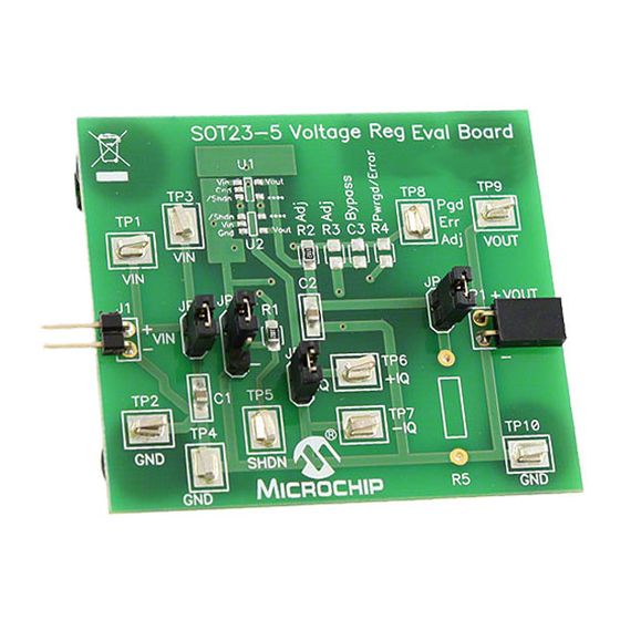
By soldering the desired device to the evaluation board, the user can easily validate several parameters of the device. 1.2.1 Funtional Blocks The SOT23-5 Voltage Regulator Evaluation Board can be broken up into six functional blocks. These blocks are: • Input Capacitance • Shutdown Control •... - Page 10 SOT23-5 Voltage Regulator Evaluation Board User’s Guide 1.2.2 Input Capacitance Jumper JP1 connects the input capacitance to the circuit. The input capacitor is disconnected when performing Power Supply Ripple Rejection tests. By default, C1 is populated with a 1 µF, 50V, XR7 ceramic capacitor.
-
Page 11: What The Sot23-5 Voltage Regulator Evaluation Board Kit Includes
Product Overview WHAT THE SOT23-5 VOLTAGE REGULATOR EVALUATION BOARD KIT INCLUDES? This SOT23-5 Voltage Regulator Evaluation Board kit includes: • One SOT23-5 Voltage Regulator Evaluation Board -102-00201 • Important Information "Read First" © 2009 Microchip Technology Inc. DS51811A-page 7... - Page 12 SOT23-5 Voltage Regulator Evaluation Board User’s Guide NOTES: © 2009 Microchip Technology Inc. DS51811A-page 8...
-
Page 13: Chapter 2. Installation And Operation
The jumpers may also be used to select pull-up and pull- down voltage levels. The SOT23-5 Voltage Regulator Evaluation Board kit comes with a 1 uF ceramic input and output capacitor soldered to the board. A 10K resistor in series with the SHDN pin is also populated on the board. -
Page 14: Getting Started
The SOT23-5 Voltage Regulator Evaluation Board is fully assembled and tested. All that is required for operating is a user supplied voltage regulator and a supply voltage source. Some of the tests that may be completed using the SOT23-5 Voltage Regulator Evaluation Board shall now be described. - Page 15 Power Supply Rejection Ratio (PSRR) Power Supply Rejection Ratio tests are performed by removing the input capacitor jumper, JP1, and connecting an appropriate PSRR analyzer to the SOT23-5 Voltage Regulator Evaluation Board. The PSRR analyzer may then sweep the input voltage frequencies and record the corresponding output voltages.
- Page 16 SOT23-5 Voltage Regulator Evaluation Board User’s Guide NOTES: © 2009 Microchip Technology Inc. DS51811A-page 12...
-
Page 17: Appendix A. Schematic And Layouts
SOT23-5 VOLTAGE REGULATOR EVALUATION BOARD USER’S GUIDE Appendix A. Schematic and Layouts INTRODUCTION This appendix contains the following schematics and layouts for the SOT23-5 Voltage Regulator Evaluation Board: • Board - Schematic • Board - Top Silk and Pads • Board - Top Copper •... -
Page 18: Board - Schematic
SOT23-5 Voltage Regulator Evaluation Board User’s Guide BOARD - SCHEMATIC © 2009 Microchip Technology Inc. DS51811A-page 14... -
Page 19: Board - Top Silk And Pads
Schematic and Layouts BOARD - TOP SILK AND PADS © 2009 Microchip Technology Inc. DS51811A-page 15... -
Page 20: Board - Top Copper
SOT23-5 Voltage Regulator Evaluation Board User’s Guide BOARD - TOP COPPER © 2009 Microchip Technology Inc. DS51811A-page 16... -
Page 21: Board - Bottom Copper
Schematic and Layouts BOARD - BOTTOM COPPER © 2009 Microchip Technology Inc. DS51811A-page 17... - Page 22 SOT23-5 Voltage Regulator Evaluation Board User’s Guide NOTES: © 2009 Microchip Technology Inc. DS51811A-page 18...
-
Page 23: Appendix B. Bill Of Materials (Bom)
SJ-5003 (BLACK) Corner RA socket, 0.100 centers, 0.025 sq pins, Sullins PPPC021LGBN-RC 0.070 pcb to pin center height RoHS Compliant Bare PCB, SOT23-5 Advanced Circuits 104-000201 Voltage Regulator Evaluation Board(250 boards, 4wk delivery) 10K Res, Smt 0805, 1%, 1/8W Rohm MCR10EZHF1002 69.8K Res, Smt 0805, 1%, 1/8W... -
Page 24: Worldwide Sales And Service
Thailand - Bangkok Santa Clara, CA Tel: 86-29-8833-7252 Tel: 66-2-694-1351 Tel: 408-961-6444 Fax: 86-29-8833-7256 Fax: 66-2-694-1350 Fax: 408-961-6445 China - Zhuhai Toronto Tel: 86-756-3210040 Mississauga, Ontario, Fax: 86-756-3210049 Canada Tel: 905-673-0699 Fax: 905-673-6509 03/26/09 © 2009 Microchip Technology Inc. DS51811A-page 20... - Page 25 Mouser Electronics Authorized Distributor Click to View Pricing, Inventory, Delivery & Lifecycle Information: Microchip SOT23-5EV-VREG...
Need help?
Do you have a question about the SOT23-5 and is the answer not in the manual?
Questions and answers