Do you have a question about the CSM 7100 and is the answer not in the manual?
Questions and answers
Ken
March 4, 2025
stopped displaying oxygen level
2 comments:
Mr. Anderson
March 4, 2025
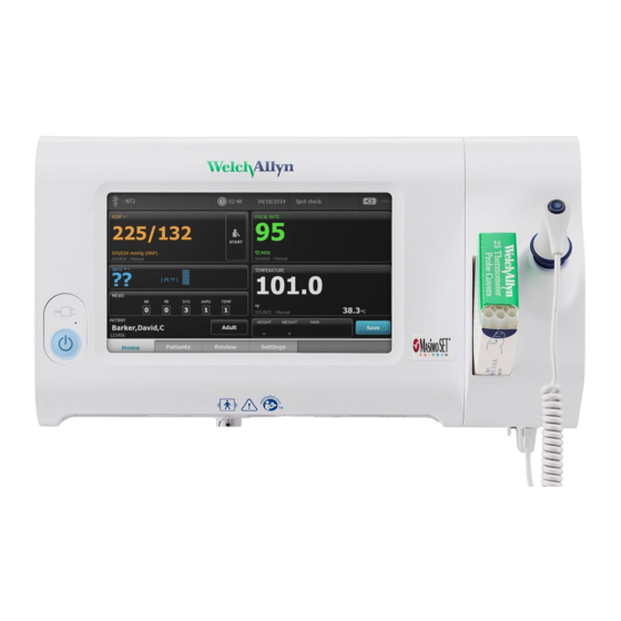
The Welch Allyn CSM 7100 may have stopped displaying the oxygen level (SpO2) due to one of the following reasons: 1. Disconnected or Faulty Sensor – Ensure the SpO2 sensor is properly connected and functioning. 2. Incorrect Model Configuration – The CSM 7100 may be a BP-only model, which does not support SpO2 measurement. 3. Cable or Connector Issues – Inspect the connectors (Locking, Friction, ZIF) for damage or improper connection. 4. Internal Component Failure – A faulty board or internal component may require replacement following troubleshooting and service instructions. 5. Software or Settings Issue – Check the device settings and ensure the SpO2 measurement is enabled.
If troubleshooting does not resolve the issue, functional verification and part replacement may be necessary.


Need help?
Do you have a question about the CSM 7100 and is the answer not in the manual?
Questions and answers
stopped displaying oxygen level
The Welch Allyn CSM 7100 may have stopped displaying the oxygen level (SpO2) due to one of the following reasons:
1. Disconnected or Faulty Sensor – Ensure the SpO2 sensor is properly connected and functioning.
2. Incorrect Model Configuration – The CSM 7100 may be a BP-only model, which does not support SpO2 measurement.
3. Cable or Connector Issues – Inspect the connectors (Locking, Friction, ZIF) for damage or improper connection.
4. Internal Component Failure – A faulty board or internal component may require replacement following troubleshooting and service instructions.
5. Software or Settings Issue – Check the device settings and ensure the SpO2 measurement is enabled.
If troubleshooting does not resolve the issue, functional verification and part replacement may be necessary.
This answer is automatically generated
How to ensure the SpO2 measurement is enabled.