
Related Manuals for Sunny Health & Fitness SF-B1423C


Summary of Contents for Sunny Health & Fitness SF-B1423C
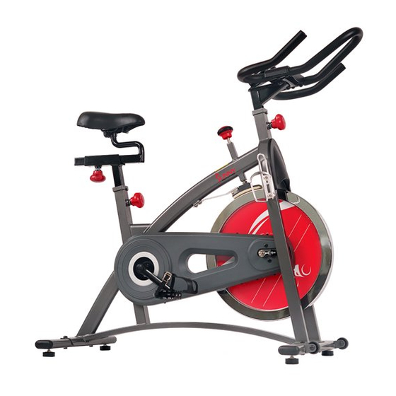
- Page 1 CHAIN DRIVE INDOOR CYCLING BIKE SF-B1423C USER MANUAL IMPORTANT: Read all instructions carefully before using this product. Retain owner’s manual future reference. customer service, please contact: support@sunnyhealthfitness.com...
-
Page 2: Important Safety Information
IMPORTANT SAFETY INFORMATION We thank you for choosing our product. To ensure your safety and health, please use this equipment correctly. It is important to read this entire manual before assembling and using the equipment. Safe and effective use can only be assured if the equipment is assembled, maintained, and used properly. -
Page 3: Exploded Drawing
EXPLODED DRAWING... -
Page 4: Parts List
PARTS LIST Description Description Foam (A) Φ23*3*550 Front cover 157*152*38.5 HIPS Crank cap Φ25*7 Handlebar cover Handlebar (A) Nut M10*1.25 *H7.5*S14 End cap Φ25*16 Pedal YH-28X 9/16″ 44L/R Crank arm 170 “L/R”9/16 Screw M8*16*S6 45L/R Cover for middle axle Φ50*Φ32*33 Bolt M10*35*15*H6 Foam grip Φ23*3*480 C clip d17... - Page 5 Description Description Screw ST4.8*10*Φ8 Trunk wire Shipping tubes Inertial wheel Spacer Φ18*Φ12.2*3 Screw M8*16*S6 Rear stabilizer Allen wrench S6 Main frame Spanner S14-15-17 Nut M35*1*Φ44*3.5...
-
Page 6: Hardware Package
HARDWARE PACKAGE... -
Page 7: Assembly Instructions
ASSEMBLY INSTRUCTIONS STEP 1: Unscrew the Screws (No. 83) with Allen Wrench (No. 90) and remove the Washers (No. 77) and Shipping Tubes (No. 82). You may discard these parts or save them in case you’d like to repackage the item in the future. [Screws (No. - Page 8 STEP 2: Attach the Front and Rear Stabilizers (No. 73 & No. 84) to the Main Frame (No. 85) using 4 Screws (No. 76) and 4 Washers (No. 77). Tighten and secure with Allen Wrench (No. 90).
- Page 9 STEP 3: Before you begin, immobilize the crank arms by turning the tension knob all the way to the right. Left Pedal: Align the Left Pedal (No. 44L) with the Left Crank Arm (No. 45L) at 90 degrees. Gently insert the pedal into the crank arm, turn the pedal counter-clockwise as tightly as you can with your hand.
- Page 10 STEP 4: Loosen and remove the [seat slider] Adjustment Knob (No. 38). Insert Seat Slider (No. 36) into the Saddle Post (No. 37). Adjust the Seat Slider (No. 36) to the desired position and reinsert and tighten Adjustment Knob (No. 38) to secure the post in place. Secure Saddle (No.
- Page 11 STEP 5: Loosen and remove the [handlebar] Adjustment Knob (No. 38). Insert Handlebar Post (No. 10) into the sleeve located on the front of the Main Frame (No. 85). Adjust the Handlebar Post (No. 10) to the desired position and reinsert and tighten the Adjustment Knob (No. 38) to secure the post in place.
-
Page 12: Exercise Computer
EXERCISE COMPUTER SPECIFICATIONS: TIME------------------------------------------- 00:00-99:59 MIN:SEC SPEED---------------------------------------- 0.0-999.9 MPH DISTANCE----------------------------------- 0.00-99.99 MI CALORIES----------------------------------- 0.0-999.9 KCAL FUNCTION KEY: MODE: Press to select function (Time, Speed, Distance, Calories) OPERATION PROCEDURES: 1. AUTO ON/OFF: Start pedaling or press the MODE button. The computer will turn on and stay on while the machine is in use. -
Page 13: Adjusting The Balance
ADJUSTMENTS & USAGE GUIDE ADJUSTING THE BALANCE In order to achieve a smooth and comfortable ride, you must ensure that the stability of the bike is secured. If you notice that the bike is unbalanced during use, you should adjust the foot levelers located beneath the front and rear stabilizers. -
Page 14: Moving The Bike
ADJUSTING THE ANGLE OF SEAT Use Spanner (No. 91) to unscrew the nut under the saddle. Adjust the saddle to the desired angle and reinstall the nut. Check the nut periodically to ensure that it is tight and secure. Use the Spanner (No.
Need help?
Do you have a question about the SF-B1423C and is the answer not in the manual?
Questions and answers