Table of Contents
Advertisement
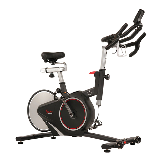
BELT DRIVE MAGNETIC INDOOR
CYCLING BIKE
SF-B1709
USER MANUAL
IMPORTANT! Please retain owner's manual for maintenance and adjustment instructions.
Your satisfaction is very important to us, PLEASE DO NOT RETURN UNTIL YOU HAVE
CONTACTED US:
support@sunnyhealthfitness.com
or 1-877-90SUNNY (877-907-8669).
Advertisement
Table of Contents

Related Manuals for Sunny Health & Fitness SF-B1709


Summary of Contents for Sunny Health & Fitness SF-B1709
- Page 1 BELT DRIVE MAGNETIC INDOOR CYCLING BIKE SF-B1709 USER MANUAL IMPORTANT! Please retain owner’s manual for maintenance and adjustment instructions. Your satisfaction is very important to us, PLEASE DO NOT RETURN UNTIL YOU HAVE CONTACTED US: support@sunnyhealthfitness.com or 1-877-90SUNNY (877-907-8669).
-
Page 2: Important Safety Information
IMPORTANT SAFETY INFORMATION We thank you for choosing our product. To ensure your safety and health, please use this equipment correctly. It is important to read this entire manual before assembling and using the equipment. Safe and effective use can only be achieved if the equipment is assembled, maintained and used properly. It is your responsibility to ensure that all users of the equipment are informed of all warnings and precautions. -
Page 3: Exploded Diagram
EXPLODED DIAGRAM 1... -
Page 4: Hardware Package
EXPLODED DIAGRAM 2 HARDWARE PACKAGE #8 M10X25 4PCS #29 M5X12 2PCS #86 S5 1PC D10XΦ20X2 4PCS #94 S4 1PC #87 S6 1PC #88 S17,19 1PC #89 S13,15 1PC... -
Page 5: Parts List
PARTS LIST Description Spec. Description Spec. Main Frame Water Bottle Holder Front Stabilizer Meter Rear Stabilizer Shipping Tube Hexagon Socket Cap M8X16 Handlebar Post Screw Adjusting Pad Extension Wire 2 Hexagon Socket Cap M6X10 Hex Nut Screws Φ8XΦ12X1 d10XΦ20X2 Flat Washer Flat Washer Hexagon Socket M10X25... - Page 6 Spring Spring Washer D6XΦ12X1.2 Hex Screw Washer D12XΦ18X0.3 Hex Bolt Wave Washer M8X50 Belt Bearing Hexagon Socket M8X20 Bolt Head Screw Stop Ring Flywheel Sleeve Allen Wrench Inner Hexagon Countersunk Head M8X25 Allen Wrench Screw S=17-19 Brake Block Wrench S=13-15 U Shape Block Wrench Cross Countersunk...
-
Page 7: Assembly Instructions
ASSEMBLY INSTRUCTIONS STEP 1: Attach 2 Adjusting Pads (No. 5) and 2 Hex Nuts (No. 6) to the Rear Stabilizer (No. 3) by using Wrench (No. 88). Unscrew the 4 Hexagon Socket Head Screws (No. 8) with Allen Wrench (No. 87), remove the 4 Flat Washers (No. - Page 8 STEP 3: Insert the Seat Post (No. 18) into the Main Frame (No. 1). Set Seat Post (No. 18) at desired height. Insert Spring Knob (No. 13) and tighten to secure. Insert the Seat Horizontal Tube (No. 20) into the Seat Post (No. 18). Insert Spring Knob (No.
- Page 9 STEP 5: Remove Hexagon Socket Cap Screw (No. 38) from Handlebar Post (No. 4) using Allen Wrench (No. 86). Unscrew preassembled Bolt (No. 28) and Washer (No. 93) from Triangle Knob (No. 26). Place Handlebar (No. 22) on Handlebar Post (No. 4). Do not slide all the way on yet.
- Page 10 ADJUSTMENTS GUIDE ADJUSTING THE BALANCE In order to achieve a smooth and comfortable ride, you must ensure that the stability of the bike is secured. If you notice that the bike is unbalanced during use, you should adjust the foot levelers located beneath the front and rear stabilizers.
-
Page 11: Dismounting The Bike
DISMOUNTING THE BIKE WARNING! Do not dismount the bike or remove your feet from the pedals until the pedals have stopped completely. You can stop the flywheel at anytime by pushing down on Brake Handle (No. 16). ADJUSTING THE HANDLEBAR Loosen the [handlebar adjustment] Spring Knob (No. -
Page 12: Maintenance Instructions
MAINTENANCE INSTRUCTIONS This is general information for daily, weekly and monthly maintenance to be performed on your bike. DAILY MAINTENANCE MONTHLY MAINTENANCE After each exercise session, wipe down all 1. Check all hardware is secure, such as: water the equipment: seat, frame, handlebars. Pay bottle holder, flywheel nuts, belt/chain guard special attention to the seat post, handlebar bolts, brake caliper lock nuts and brake... - Page 13 EXERCISE METER FUNCTION BUTTONS MODE Press to select the function displayed or enter value after setting. Press and hold for 2 seconds to enter the RACE interface in STOP mode. To set up the target value of TARGET, TIME, DIST, CAL. Press the button and hold for 2 seconds to speed up the increment during stop mode.
- Page 14 4. TIME will flash. 5. Press SET to select a value. 6. Press MODE to enter. 7. Repeat to select values for DIST and CAL. RACE MODE Press and hold MODE for 2 seconds to enter RACE mode. 1. TARGET: the preset CADENCE. 2.
- Page 15 PULSE To measure the pulse, press MODE until meter is on the PULSE function. Hold the contact pads for at least 5 seconds to measure your pulse. This value is for reference only. It cannot be used as the basis for medical treatment.
Need help?
Do you have a question about the SF-B1709 and is the answer not in the manual?
Questions and answers