Table of Contents

Related Manuals for Sunny Health & Fitness SF-B1516


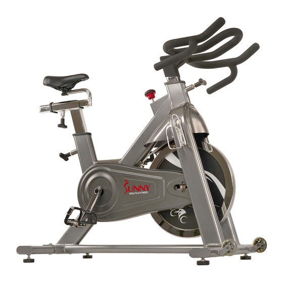
Summary of Contents for Sunny Health & Fitness SF-B1516
- Page 1 COMMERCIAL INDOOR CYCLING BIKE SF-B1516 USER MANUAL IMPORTANT! Read all instructions carefully before using this product. Retain owner’s manual for future reference. For customer service, please contact: support@sunnyhealthfitness.com...
-
Page 2: Important Safety Information
IMPORTANT SAFETY INFORMATION We thank you for choosing our product. To ensure your safety and health, please use this equipment correctly. It is important to read this entire manual before assembling and using the equipment. Safe and effective use can only be assured if the equipment is assembled, maintained, and used properly. -
Page 3: Exploded Drawing
EXPLODED DRAWING 1... -
Page 4: Hardware Package
EXPLODED DRAWING 2 28 55 HARDWARE PACKAGE d10*Φ20*2 4PCS... -
Page 5: Parts List
PARTS LIST Description Description Washer d6*Φ12*1.2 Handlebar Bushing PT100*40*J60*30*188 Brake rod Saddle Nut M5*H9*S8 Seat slider tube Brake block 12*25*138 Saddle post Screw M5*12*Φ10 Bushing PTB45*51*2.0*PTB35*41*L198 Nut M5*H4*S8 D shape end cap Spring piece t2.0*15.8*153 EVA pad 22*75 T shape knob 1 Cow leather pad t5*25*138 Screw M5*20*Φ8.5 10 T shape knob 2... -
Page 6: Assembly Instructions
ASSEMBLY INSTRUCTIONS STEP 1: Unscrew the 2 Screws (No. 26) with Allen Wrench (No. 34) and remove the 2 Flat Washers (No. 18), Shipping Front Tube (No. 25) and Shipping Rear Tube (No. 30). You may save these parts [Screws (No. 26), Flat Washers (No. 18), Shipping Front Tube (No. 25) and the Shipping Rear Tube (No. - Page 7 #17 M10*25*S6 4PCS #18 d10*Φ20*2 4PCS STEP 2: Attach the Front and Rear Stabilizers (No.16 and No.29) to the Main Frame (No. 28) using 4 Screws (No. 17) and 4 Flat Washers (No. 18). Tighten and secure with Allen Wrench (No. 34).
- Page 8 #23 M5*16*Φ8.5 2PCS #11 d5*Φ13*1 2PCS STEP 3: Connect the Left and Right Pedals (No. 27L and No. 27R) to the Left and Right Crank Arms (No. 32L and No. 32R). Before you begin, immobilize the crank arms by turning the tension knob all the way to the right.
- Page 9 STEP 4: Loosen and pull out the [seat] Height Adjustment Knob (No. 10). Insert the Saddle Post (No. 5) into the tube located on the back of the Main Frame (No. 28). Adjust the Saddle Post (No. 5) to the desired height then secure it in place by reinserting and tightening the Height Adjustment Knob (No.
- Page 10 STEP 5: Loosen and pull out the [handlebar] Height Adjustment Knob (No.10). Insert the Handlebar (No. 1) into the tube located on the front of the Main Frame (No. 28). Adjust the Handlebar (No. 1) to the desired height then secure it in place by reinserting and tightening the Height Adjustment Knob (No.10).
-
Page 11: Adjustment Guide
ADJUSTMENT GUIDE ADJUSTING THE HEIGHT AND BALANCE In order to achieve a smooth and comfortable ride, you must ensure that the stability of the bike is secured. If you notice that the bike is unbalanced during use, you should adjust the Foot Levelers (No. -
Page 12: Adjusting The Saddle
ADJUSTING THE SADDLE The seat of this bike is fully adjustable as it moves Up, Down, Fore (forward), Aft (backward). To adjust the height of the Saddle Post (No. 5), loosen and pull the [seat] Height Adjustment Knob (No. 10) outward, then raise or lower the saddle to the desired height. Once adjusted, re-insert and tighten the Height Adjustment Knob (No. -
Page 13: Adjusting The Resistance
PEDAL STRAP ADJUSTMENT Your feet should be secured in the toe clips during exercise. Place your feet as far forward into the toe-clips as you can. With your feet in place, turn the crank to bring one foot to within arm’s reach then grasp the pedal strap and pull it upward to tighten the toe-clip cage. - Page 14 MOVING THE BIKE & BRAKING/DISMOUNTING TRANSPORTING THE BIKE To move the bike, first ensure that the Handlebar (No. 1) is properly secured. If the handlebar is loose, tighten the [handlebar] Height Adjustment Knob (No. 10) to secure it. Next, stand at the front of the bike so that you’re directly in front of the handlebar.
- Page 15 REMOVING THE CRANK TO REMOVE THE CRANK Unscrew Screw (No. 52) counter-clockwise with the Allen Wrench (No. 34). Remove the Screw (No. 52) and pull out the Crank Arms (No. 32L & 32R). NOTE: The hexagonal hole on the middle axle and the crank should be aligned when assembling ...
Need help?
Do you have a question about the SF-B1516 and is the answer not in the manual?
Questions and answers