Table of Contents
Advertisement
Quick Links
Advertisement
Table of Contents

Related Manuals for CAME ZE5


Summary of Contents for CAME ZE5
- Page 1 CONTROL PANEL FOR EMEGA SERIES 3 19 T 92EN Installation manual English...
- Page 2 Destination Engineered and built entirely by Came Cancelli Automatici S.p.A. The ZE5 electrical panel is designed to control EMEGA (E306-E456) automation units in the movement of garage- The control panel is powered by 230 v AC on terminals L type doors with double or single motor.
- Page 3 Dimensions Technical data TE CH NI C AL DATA Power supply 230 V - 50/60 Hz Maximum allowed power load 400 W Power draw when idle 150 mA Maximum power rating for 24V 40 W accessories Circuit insulation class Container material ABS Degree of protection IP54 Working temperature -20 / +55 °C FUSE TA BL E...
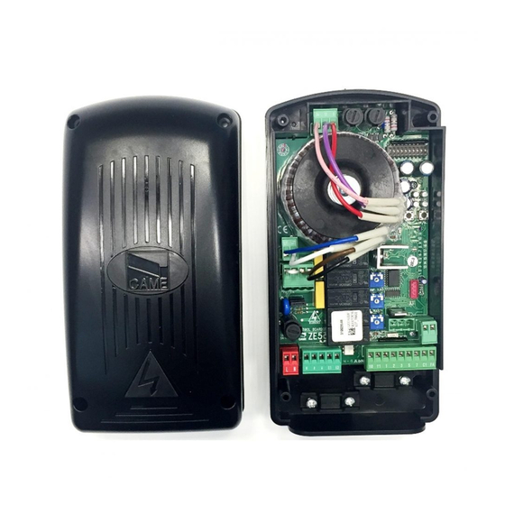
- Page 4 Main Components 630 mA board fuse 1.6 A fuse for accessories • •• • • • • • • • • • • • • • • • • • •• • Dip-Switch for function selector Keys for radio code memorisation and for end-stop 1 2 3 4 5 6 7 8 9 1 0 programming...
- Page 5 Installation Preliminary checks Equipment and materials Make sure all the necessary tools and materials are avai- Before proceeding with the installation, it is necessary to : lable to carry out the installation with the maximum safe- ty, in compliance with regulations in force. Here are some •...
- Page 6 Minimum thicknesses and cables types Cable Length Cable Length Cable Length Connections Cable Type 1 < 10 m 10 < 20 m 20 < 30 m 230V 2F power supply 3G 1,5mm² 3G 2,5mm² 3G 4mm² 230V 2F motors 4G 1mm² 4G 1,5mm²...
- Page 7 Anchoring and installing the box E306/E456 Ratiomotor 24 12 1 2 3 4 5 6 7 8 9 1 0 L1T L2T - A.C.T.+ - AMP. S+ - S. DELAY + E1 E3 10 11 1 7 C1 FA Use a ø 5 drill bit to bear a hole observing the distance between the centres as specified in paragraph 5.3, and secure the control panel to the ground guide using M 4x39 screws...
- Page 8 Electrical connections Gearmotor 230V (a.c.) max. 400 W single-phase motor CONTROL LINE BOARD EMEGA 10 11 1 Power supply -ENC+ -ENC+ CONTROL CONTROL LINE LINE BOARD BOARD Terminals for powering the Power supply to the 230V AC 50/60 Hz 24V AC accessories. control panel Overall allowed power: 20W...
- Page 9 Signalling and lighting devices Flashing light (contact rated for: 230V AC - 25W Max.) Flashes while gate opens and closes. (E881) Dip 9 in ON = Gate open warning light Contact rated for: 24 V - 3 W Max.). Indicates that gate is open. Dip 9 in OFF = 24V-15W max.
- Page 10 Safety devices Delta-S C1 = (N.C.) contact for reopening while closing - Input for safety devices like photocells, sensitive -ENC+ edges and other devices that comply with EN 12978 regulations. While the door is closing, opening the contact will invert movement until it is fully openend.
- Page 11 Command devices Stop button ((N.C.) contact.) - Gate stop button with exclusion of automatic closing, to resume movement press command button or transmitter button. Shortcircuit 1 and 2 if unused. Key switch selector and/or opening button (N.O. contact) - Command for gate opening. -ENC+ Selettore a chiave e/o pulsante per comandi Selettore a chiave e/o pulsante per comandi (contatto N.O.)
- Page 12 Encoder Programming Adjustment of stop micro-switch during opening FIG.1 Release the ratiomotor and move the door manually to approximately 30 mm from the desired opening. Rotate the cam until the micro-switch can be inserted and tighten the screw in the cam. Relock the ratiomotor.
- Page 13 Press the “CLOSE” button and let the garage door close fully. CH1/OP CLOSE OP/CL ï ï ï ï ï ï ï ï ï ïï ï ï Press the “OP/CL” button: the signalling LED with stay lit ï ï (to show memorisation of the “close” end point); it will then •...
- Page 14 Opening End-Stop Press “CH1/OP” and allow the door to open completely. CH1/OP CLOSE OP/CL ï ï ï ï ï ï ï ï ï ïï ï ï Press the “OP/CL” key: the LED indicator remains lit to signal the memorisation of the open end-stop. •...
- Page 15 ï ï ï ï ï ï 8 OFF Reset dip-switch 8 to OFF. ï ï ïï Note: if the LED indicator begins to flash rapidly after resetting dip 8, it is necessary to repeat the 1 2 3 4 5 6 7 8 9 1 0 procedure from the beginning.
- Page 16 Connecting Two Motors Should two motors be installed, connect them in parallel. Use terminals U, V and W of the ZE5 control panel to connect both motors. Connect the encoder and the opening end-stop of a single motor. FA K U V W E1 E3 The data and information reported in this installation manual are susceptible to change at any time and without obligation to notify users.
- Page 17 FA K The data and information reported in this installation manual are susceptible to change at any time and without obligation to notify users.
- Page 18 Dip-switch Functions C. BOARD ACCES. 1 ON Automatic closing activated; 630mA 1,6A 1 2 3 4 5 6 7 8 9 1 0 2 ON “Open-stop-close-stop” with key (2-7) and radio remote control (AF board inserted) activated; CH1/OP. CLOSE OP./CL. - A.C.T.+ 2 OFF “Open-close”...
- Page 19 Settings Trimmers C. BOARD ACCES. 630mA 1,6A 1 2 3 4 5 6 7 8 9 1 0 A.C.T. Trimmer = Adjusting the time for automatic closing activation: CH1/OP. CLOSE OP./CL. min 1s (-) / max 120s (+) - A.C.T.+ - A.C.T.+ - AMP.
- Page 20 Adjusting the motor torque Connector “A” To reduce the motor torque, move the Connector “A” terminal board to Connector “B”. To increase the motor torque, Connector “B” 10 11 1 7 C1 FA isolate the black and brown wires and insert a bridge as shown in the diagram.
- Page 21 Activating the radio command ï ï ① Connect RG58 antenna cable to the apposite terminals. 7 C1 FA ② Only for the AF43S / AF43SM radiofrequency cards: - position jumper as shown depending on the series of transmitters you are using. “AF”...
- Page 22 Code Memorisation ① Keep the “CH1/OP” key pressed down ② the code is sent by means of a transmitter key, on the control board (the LED indicator and the LED indicator will remain lighted to signal flashes); that that memorisation has taken place. CH1/OP CLOSE OP/CL...
- Page 23 Vi chiediamo di continuare l’opera di tutela dell’ambiente, differenziato nei centri autorizzati. che CAME considera uno dei fondamenti di sviluppo delle Altri componenti (schede elettroniche, batterie dei proprie strategie operative e di mercato, semplicemente radiocomandi etc.) possono invece contenere sostanze...
- Page 24 For any further information on company, products and assistance in your language: www. came.com www. came.com CAME Cancelli Automatici S.p.a. CAME Cancelli Automatici S.p.a. Via Martiri Della Libertà, 15 31030 Dosson Di Casier Dosson Di Casier (Tv) (+39) 0422 4940...
Need help?
Do you have a question about the ZE5 and is the answer not in the manual?
Questions and answers