
Subscribe to Our Youtube Channel
Related Manuals for CAME ZE5 V.7


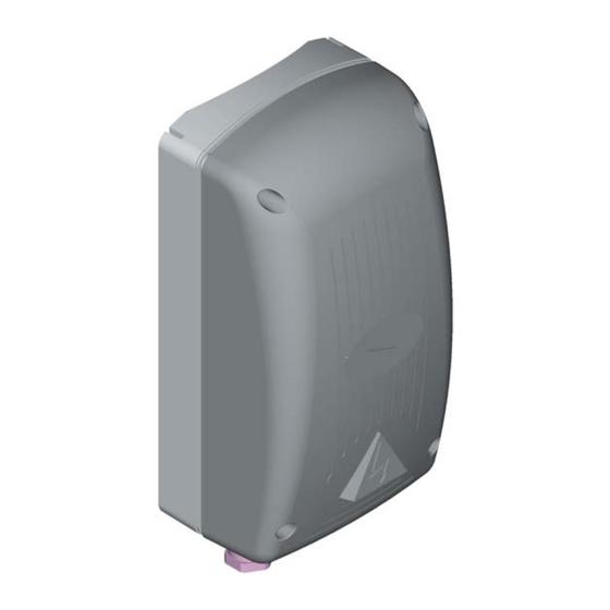
Summary of Contents for CAME ZE5 V.7
- Page 1 AUTOMAZIONE PER CHIUSURA INDUSTRIALE CONTROL PANEL FOR EMEGA SERIES INSTALLATION MANUAL...
-
Page 2: Standards Followed
UNI EN 12453. 4 Device Description 4.1 Components 230V electric panel for EMEGA series automation systems; 50÷60 Hz frequency. Wholly designed and built by CAME Cancelli Automatici S.p.A. Guaranteed 24 months if not tampered with. 4.2 Technical Information Electric Panel Power supply: 230V, 50÷60 Hz. -
Page 3: Main Components
4.3 Main Components 1 630 mA board fuse 2 1.6 A fuse for accessories 3 Dip-Switch for function selector 5 6 7 8 9 1 0 1 2 3 4 4 Keys for radio code memorisation and for end- stop programming 5 LED indicator 6 Trimmer for adjusting automatic closing times CH1/OP. - Page 4 5.3 Dimensions, axle bases and fastening holes 5.4 Minimum thicknesses and cables types 1<10 m Cable 10<20 m 20<30 m Cable Connections Cable Type Length Cable Length Length 230V 2F power supply 3G 1,5mm² 3G 2,5mm² 3G 4mm² 230V 2F motors 4G 1mm²...
- Page 5 Pre-settings, Fixing the Electric Board to the Ground Guide (Art. 001E001) and Ratiomotor Electric Connections E306/E456 Ratiomotor Use a ø 5 drill bit to bear a hole observing the distance between the centres as specifi ed in paragraph 5.3, and secure the control panel to the ground guide using M 4x39 screws (provided).
- Page 6 CONTROL LINE 5.6 Connections BOARD 10 11 11 1 7 C1 C1 FA 230V (a.c.) power supply 230V (a.c.) max. 400 W single-phase motor 230V (a.c.) output in movement (e.g. fl ashing lamp - max. 25W) 230V (a.c.) courtesy lamp output (max. 60W) 24V (a.c.) (max.
-
Page 7: Dip Switch Functions
5.7 Dip-switch Functions 5 6 7 8 9 1 0 1 2 3 4 1 ON Automatic closing activated; 2 ON “Open-stop-close-stop” with key (2-7) and radio remote control (AF board inserted) activated; 2 OFF “Open-close” with key (2-7) and radio remote control (AF board inserted) activated; 3 ON “Opening only”... - Page 8 5.9 Encoder Programming IMPORTANT: READ INSTRUCTIONS CAREFULLY BEFORE PROCEEDING WITH PROGRAMMING. Adjustment of stop micro-switch during opening Release the ratiomotor and move the door manually to approximately 30 mm from the desired opening. Rotate the cam until the micro-switch can be inserted and tighten the screw in the cam. Relock the ratiomotor.
- Page 9 Opening End-Stop Press “CH1/OP” and allow the door to open completely. Press the “OP/CL” key: the LED indicator remains lit to signal the memorisation of the open end-stop. Note: if the “CH1/OP” key is pressed twice within 15”, the slowing during closing mode is deactivated and the 10 11 1 7 C1 FA “thrust reduction”...
- Page 10 5.10 Connecting Two Motors Should two motors be installed, connect them in parallel. Use terminals U, V and W of the ZE5 control panel to connect both motors. Note: Connect the encoder and the opening end-stop of a single motor. C.
- Page 11 6 Radio Remote Control Installation Procedure Please read the following instructions carefully prior to installation: - preparing the radio board (par. 6.1); C. BOARD ACCES. 630mA 1,6A - transmitter encoding procedure (par. 6.2); - control board code memorisation (par. 6.3). 6.1 Preparing the Radio Board (AF) 1) For transmitters with 433.92 AM frequencies (TOP and TAM series) position the jumper on the...
- Page 12 T262M - T302M The fi rst code should be recorded by keeping the jumpers positioned for channels 1 and 2 as in fi g. A; see fi g. B for any further settings on different channels. P1 = CH1 - P2 = CH3 P1 = CH3 - P2 = CH2 FIG.A FIG.B...
- Page 13 Top Series T432M - T312M Set the code to dip-switch C and the channel to D (P1 = CH1 and P2 = CH2, default setting) T434M - T314M T432S - T432SA - T434MA - T432NA - T434NA Set the code only See instructions in the P1 = CH1 package...
-
Page 14: Solving Problems
6.3 Code Memorisation -Keep the “CH1/OP” key pressed down on the control board (the LED indicator fl ashes); LED indicator flashes - the code is sent by means of a transmitter key, and the LED indicator will remain lighted to signal that that LED indicator is lit 10 11 1 7 C1 FA... -
Page 15: Demolition And Disposal
System certifi ed in compliance with the UNI EN ISO 14001 standard to ensure environmental protection. Please continue our efforts to protect the environment—which CAME considers one of the cardinal elements in the development of its operational and market strategies—simply by observing brief recommendations as regards disposal: DISPOSAL OF PACKAGING –... - Page 16 CAME UNITED KINGDOM LTD UNIT 3, ORCHARD BUSINESS PARK TOWN STREET, SANDIACRE NOTTINGHAM - NG10 5BP - U.K. 0044 115 9210430 0044 115 9210431...
Need help?
Do you have a question about the ZE5 V.7 and is the answer not in the manual?
Questions and answers