
Related Manuals for CAME ZR24N


Summary of Contents for CAME ZR24N
- Page 1 QUADRO COMANDO FA00943M04 FA00943-IT PER MOTORIDUTTORI A 230 V Italiano EN English FR Français ZR24N RU Pусский MANUALE DI INSTALLAZIONE...
- Page 2 • Il prodotto deve essere destinato solo all’uso per il quale è stato espres- samente studiato. Ogni altro uso è da considerarsi pericoloso. CAME S.p.A. non è re- sponsabile per eventuali danni causati da usi impropri, erronei ed irragionevoli • Prima di installare l’automazione verificare che la parte guidata sia in buono stato meccanico,...
- Page 3 si devono eseguire osservando la regola dell’arte e in ottemperanza alle norme e leggi vigenti • Verificare che il range di temperatura indicato sia adatto al luogo di installa- zione • Delimitare accuratamente l’intero sito per evitare l’accesso da parte di persone non autorizzate, in particolare minori e bambini •...
- Page 4 autorizzato o comunque da personale debitamente qualificato per evitare ogni rischio • Durante tutte le fasi dell’installazione assicurarsi di operare fuori tensione • I cavi elettrici devono passare attraverso apposite tubazioni o canaline al fine di garantire un’adeguata protezione contro il danneggiamento meccanico e non devono entrare in contatto con parti che possono riscaldarsi durante l’uso •...
- Page 5 Tutte le connessioni e i collegamenti sono protetti da fusibili. Destinazione d’uso Il quadro comando ZR24N è stato progettato per il controllo di motoriduttori per serrande avvolgibili CAME della serie H ad uso residenziale e commerciale. Ogni installazione e uso diff ormi da quanto indicato nel seguente manuale sono da considerarsi vietate.
- Page 6 Dimensioni Dati tecnici Tipo ZR24N Grado di protezione (IP) Alimentazione (V - 50/60 Hz) 230 AC Assorbimento in stand-by (W) CAME Potenza motore (W) Potenza accessori max (W) Materiale del contenitore Temperatura di esercizio (°C) -20 ÷ +55 Classe dell'apparecchio...
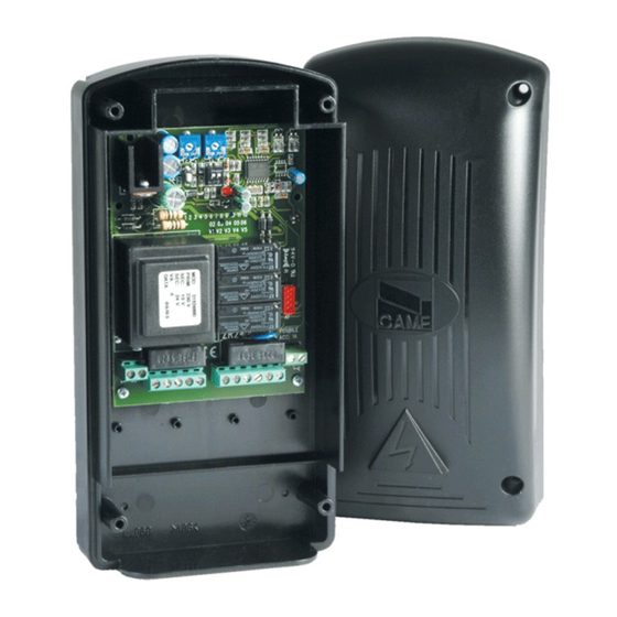
- Page 7 Descrizione delle parti Morsettiere collegamento Fusibile linea Fusibile dispositivi e accessori Trimmer regolazione tempo lavoro Trimmer chiusura automatica DIP selezione funzioni Pulsante memorizzazione LED programmazione (PRG) LED alimentazione (PWR) Connettore scheda AF...
- Page 8 INSTALLAZIONE Tipi di cavi e spessori minimi lunghezza cavo Collegamento < 20 m 20 < 30 m Quadro comando 120 / 230 V AC (1P+N+PE) 3G x 1,5 mm 3G x 2,5 mm Motoriduttore 120 / 230 V AC 4G x 1,5 mm 4G x 2,5 mm Fotocellule TX 2 x 0,5 mm...
- Page 9 Fissaggio del quadro comando ❶ Fissare la base del quadro in una zona protetta con viti e tasselli adeguati ❷ Forare sui fori presfondati sotto la base del quadro. ⚠ Non danneggiare la scheda elettronica all’interno del quadro. ❸ Forare sui fori presfondati e inserire i pressacavi con i tubi corrugati per il passaggio dei cavi elettrici. ❶...
- Page 10 COLLEGAMENTI ELETTRICI Eseguire i collegamenti elettrici secondo le disposizioni vigenti utilizzando dei pressacavi idonei. ⚠ Utilizzare un pressacavo solo per il cavo di alimentazione 230 V AC. ⚠ Effettuare le opportune connessioni tra la terra di protezione dell’impianto elettrico e il morsetto di terra di protezione del motore.
- Page 11 Dispositivi di comando Funzione APRE - CHIUDE - INVERSIONE (passo-passo) da dispositivo di comando (contatto NO). In alternativa, con il DIP 2 in ON è possibile attivare il comando APRE-STOP-CHIUDE-STOP (sequenziale). Pulsante di STOP (contatto NC). Permette l’arresto della serranda on l’esclusione della chiusura automatica.
- Page 12 Dispositivi di sicurezza Fotocellule Ingresso per dispositivi di sicurezza tipo fotocellule. C1 RIAPERTURA DURANTE LA CHIUSURA: in fase di chiusura della serranda, l’apertura del contatto provoca l’inversione del movimento fi no alla completa apertura; C7 RIAPERTURA DURANTE LA CHIUSURA: in fase di chiusura della serranda, l’apertura del contatto provoca l’inversione veloce del movimento fi...
- Page 13 10 11 1 2 7 C1 C7 TS 10 11 1 2 7 C1 C7 TS 10 11 1 2 7 C1 C7 TS - NO C NC TX - 10 2 TX C TX 2 TX 2 DELTA DELTA-S DFWN...
- Page 14 Collegamento dei dispositivi di sicurezza (test sicurezza) A ogni comando di apertura o di chiusura, la scheda verifi ca l'effi cienza dei dispositivi di sicurezza (es. fotocellule). Un’eventuale anomalia inibisce qualsiasi comando. Per questo tipo di collegamento, abilitare la funzione con il DIP 3 in ON. 10 11 1 2 7 C1 C7 TS 10 11 1 2 7 C1...
- Page 15 FUNZIONI E REGOLAZIONI ⚠ Tutte le impostazioni devono essere eseguite ad automazione ferma. DIP-SWITCH funzioni TRIMMER regolazioni TEMPO LAVORO CHIUSURA AUTOMATICA Chiusura automatica attiva (1 OFF - Regola il tempo lavoro dei motoriduttori. Il tempo lavoro può essere regolato da 10 a 120 secondi. Disattivata) ...
- Page 16 GESTIONE UTENTI CON COMANDO RADIO Descrizione delle segnalazioni del LED del tasto PRG - Lampeggio veloce per segnalare la presenza di un ostacolo davanti alle fotocellule. - Lampeggio ogni secondo per tutto il tempo della chiusura automatica se attiva (con ostacoli sulle fotocellule durante il tempo di chiusura automatica, il LED resta acceso fi...
- Page 17 Inserimento di un utente È possibile registrare fi no ad un massimo di 50 utenti; oltre i 50, il LED PRG lampeggia veloce e l’utente non viene memorizzato. ❶ Tenere premuto il tasto PROG sulla scheda elettronica. Il LED lampeggia. ❷ Premere un tasto del trasmettitore da memorizzare.
- Page 18 Cancellazione di un singolo utente già memorizzato Posizionare il DIP 4 in ON. Tenere premuto il tasto PROG sulla scheda elettronica. Il LED di programmazione lampeggia. Entro 5 secondi, premere il tasto del trasmettitore dell'utente da cancellare. Il LED lampeggia velocemente per un secondo a segnalare l’avvenuta cancellazione dopodichè...
- Page 19 Cancellazione di tutti gli utenti Posizionare il DIP 4 in ON. Tenere premuto il tasto PROG sulla scheda elettronica per 10 secondi circa. Il LED di programmazione eseguirà una serie di lampeggi fi no allo spegnimento. Riposizionare il DIP 4 in OFF. OPERAZIONI FINALI Fissaggio del coperchio Terminati i collegamenti elettrici e la messa in funzione, inserire il coperchio e fi...
- Page 20 NON DISPERDERE NELL’AMBIENTE! RIFERIMENTI NORMATIVI CAME SPA dichiara che il prodotto è conforme alle direttive di riferimento vigenti al momento della produzione dello stesso. I contenuti del manuale sono da ritenersi suscettibili di modifica in qualsiasi momento senza obbligo di preavviso.
- Page 21 CONTROL PANEL FA00943-EN FOR 230 V GEARMOTORS ZR24N EN English INSTALLATION MANUAL...
- Page 22 • This product should only be used for the purpose for which it was explicitly designed. Any other use is dangerous. CAME S.p.A. is not liable for any damage caused by improper, wrongful and unreasonable use. • Before...
- Page 23 especially children and minors. • Use proper means of protection to prevent any me- chanical hazards from people caught in the movement of the automated operator. Any residual risks must be highlighted by fitting pictograms, in clear view. These must then be explained to the end user of the machinery.
- Page 24 that is compliant with the installation rules. It should completely cut off the power supply according to category III surcharge conditions. • If the control panel is used for automa- ting guided parts in residential settings, permanently fit the entrapment-hazard-warning signage, so that it is clearly visible or close enough to all command and control devices.
- Page 25 All connections are protected by fuses. Intended use The ZR24N control panel is designed for controlling gearmotors for CAME, H-series, winding motors for shutters in homes and businesses. Any installation and/or use other than that specifi ed in this manual is forbidden.
- Page 26 Dimensions Technical data Type ZR24N Protection rating (IP) Power supply (V - 50/60 Hz) 230 AC Draw when in stand-by (W) CAME Motor power (W) Maximum power of the accessories (W) Casing material Operating temperature (°C) -20 to +55 Apparatus class...
- Page 27 Description of parts Connection terminals Line fuse Devices and accessories fuse. Operating-time adjusting trimmer Automatic closing trimmer Functions selection DIP switches Saving button Programming LED (PRG) Power-supply LED (PWR) AF card connector...
- Page 28 INSTALLATION Cable types and minimum thicknesses cable length Connection < 20 m 20 < 30 m Control panel 120 / 230 V AC (1P+N+PE) 3G x 1.5 mm 3G x 2.5 mm Gearmotor 120 / 230 V AC 4G x 1.5 mm 4G x 2.5 mm TX Photocells 2 x 0.5 mm...
- Page 29 Fastening the control panel ❶ Fasten the control panel's base so that it is protected, and use suitable wall-plugs and screws. ❷ Drill the marked holes beneath the control panel's base. ⚠ Keep the control board undamaged, inside the control panel. ❸...
- Page 30 ELECTRICAL CONNECTIONS Perform the electrical connections in compliance with current provisions of law and use suitable cable glands. ⚠ Use a cable gland only for the 230 V AC power supply cable. ⚠ Connect the system's protective grounding to the motor's ground terminal. ⚠ Use electrical bands or tape to keep separate the 230 V ac cables from the VERY-LOW tension ones.
- Page 31 Command and control devices OPEN - CLOSE - INVERT function (step-step) from control device (NO contact). Alternatively, by setting DIP-switch 2 to ON, you can activate the OPEN-STOP-CLOSE-STOP sequential command. STOP button (NC contact). For stopping the shutter while excluding the automatic closing.
- Page 32 Safety devices Photocells Input for safety devices such as photocells. C1 REOPENING DURING CLOSING: when the shutter is closing, opening the contact triggers an inversion of movement, until it is completely open again. C7 REOPENING DURING CLOSING: when the shutter is opening, opening the contact triggers a quick inversion of movement, until it is completely open again.
- Page 33 10 11 1 2 7 C1 C7 TS 10 11 1 2 7 C1 C7 TS 10 11 1 2 7 C1 C7 TS - NO C NC TX - 10 2 TX C TX 2 TX 2 DELTA DELTA-S DFWN...
- Page 34 Connecting the safety devices (i.e. the safety test) At each opening and closing command, the control board checks the effi cacy of the safety devices (such as, photocells). Any anomalies will inhibit all commands. For this type of connection, enable the function by setting DIP-switch 3 to ON. 10 11 1 2 7 C1 C7 TS 10 11 1 2 7 C1...
- Page 35 FUNCTIONS AND SETTINGS ⚠ Perform all settings only when the shutter is not moving and completely stopped. Functions DIP-SWITCH Adjusting TRIMMER OPERATING TIME AUTOMATIC CLOSING This sets the gearmotors' operating time. The operating Automatic closing active (1 OFF - time can be adjusted to between 10 and 120 seconds. Deactivated) ...
- Page 36 MANAGING USERS BY RADIO CONTROL Description of the warnings of the PRG button's LED. - Quick fl ashing to warn that there is an obstruction in front of the photocells. - Flashing every second for the entire automatic-closing time - if it is activated, that is, when there are obstructions in front of the photocells during the automatic-closing time, the LED stays on steady until the obstruction is removed, after which, the count for the automatic closing restarts from zero and the LED fl...
- Page 37 Adding a user You can register up to 50 users; over 50, the PRG LED will fl ash quickly and any additional users will not be saved. ❶ Keep pressed the PROG button on the control board. The LED fl ashes quickly. ❷ Press any key on the transmitter you want to memorize.
- Page 38 Deleting single users that have been previously saved. Set DIP-switch 4 to ON. Keep pressed the PROG button on the control board. The programming LED fl ashes. Within fi ve seconds, press the button on the transmitter of the user you wish to delete. The LED will fl ash quickly for one second to signal that the user has been deleted, and then it will switch off .
- Page 39 Deleting all users Set DIP-switch 4 to ON. Keep pressed for about 10 seconds the PROG button on the control board. The programming LED will perform a series of fl ashes until shut down. Reset DIP-switch 4 to OFF. FINAL OPERATIONS Fastening the cover Once fi...
- Page 40 DISPOSE OF RESPONSIBLY! REFERENCE REGULATIONS CAME SpA declares that this product complies with the current directives at the time it is manufactured. The contents of this manual may change, at any time, and without notice. CAME S.p.A.
- Page 41 ARMOIRE DE COMMANDE FA00943-FR POUR MOTORÉDUCTEURS 230 V ZR24N FR Français MANUEL D'INSTALLATION...
- Page 42 être exécutées que par du personnel qualifié • Le produit ne devra être destiné qu'à l'utilisation pour laquelle il a été expressément conçu. Toute autre utilisation est à considérer comme dangereuse. CAME S.p.A. décline toute responsabilité en cas de dommages provoqués par des utilisations impropres, incorrectes ou déraisonnables •...
- Page 43 réalisée au moyen d'éléments appropriés (vis, chevilles, etc.) à la surface • La position des câbles, la pose, la connexion et l'essai doivent être réalisés selon les règles de l'art et conformément aux normes et lois en vigueur • S'assurer que la température du lieu d'installation correspond à...
- Page 44 son remplacement doit être effectué par le fabricant, ou par son service d'assistance technique agréé, ou par une personne dûment qualifiée afin de prévenir tout risque • S’assurer, durant toutes les phases d’installation, que l’automatisme est bien hors ten- sion • Les câbles électriques doivent passer à travers des tuyaux ou des conduites spé- cifiques afin de garantir une protection adéquate contre toute détérioration mécanique et ne doivent pas entrer en contact avec des parties pouvant devenir chaudes durant l’utilisation •...
- Page 45 Toutes les connexions sont protégées par des fusibles. Utilisation prévue L’armoire de commande ZR24N a été conçue pour le contrôle de motoréducteurs pour rideaux roulants CAME à usage résidentiel et commercial de la série H. Toute installation et toute utilisation autres que celles qui sont indiquées dans ce manuel sont interdites.
- Page 46 Dimensions Données techniques Type ZR24N Degré de protection (IP) Alimentation (V - 50/60 Hz) 230 AC Absorption en mode veille (W) CAME Puissance moteur (W) Puissance accessoires max. (W) Matériau du boîtier Température de fonctionnement (°C) de -20 à +55 Classe de l’appareil...
- Page 47 Description des parties Barrettes de connexion Fusible de ligne Fusibles dispositifs et accessoires Trimmer de réglage du temps de fonctionnement Trimmer de fermeture automatique Micro-interrupteurs DIP sélection fonctions Bouton mémorisation LED programmation (PRG) LED alimentation (PWR) Connecteur carte AF...
- Page 48 INSTALLATION Types de câbles et épaisseurs minimum longueur câble Connexion < 20 m 20 < 30 m Armoire de commande 120 / 230 VAC (1P+N+PE) 3 G x 1,5 mm 3 G x 2,5 mm Motoréducteur 120 / 230 VAC 4 G x 1,5 mm 4 G x 2,5 mm Photocellules TX...
- Page 49 Fixation de l'armoire de commande ❶ Fixer la base de l’armoire dans une zone protégée à l'aide de vis et de chevilles spécifi ques ❷ Percer les trous préforés sous la base de l'armoire. ⚠ Ne pas endommager la carte électronique à l'intérieur de l'armoire. ❸...
- Page 50 BRANCHEMENTS ÉLECTRIQUES Effectuer les branchements électriques selon les dispositions en vigueur en utilisant des passe-câbles appropriés. ⚠ Utiliser un passe-câble uniquement pour le câble d’alimentation 230 VAC. ⚠ Effectuer les connexions entre la mise à la terre de l’installation électrique et la borne de mise à la terre du moteur. ⚠ À...
- Page 51 Dispositifs de commande Fonction OUVERTURE - FERMETURE - INVERSION (pas-à-pas) depuis un dispositif de commande (contact NO). Il est également possible, avec DIP 2 sur ON, d’activer la commande OUVERTURE- ARRÊT-FERMETURE-ARRÊT (séquentielle). Bouton d'ARRÊT (contact NF). Permet l'arrêt du store avec désactivation de la fermeture automatique.
- Page 52 Dispositifs de sécurité Photocellules Entrée pour dispositifs de sécurité type photocellules. C1 RÉOUVERTURE DURANT LA FERMETURE : durant la phase de fermeture du store, l'ouverture du contact provoque l'inversion du mouvement jusqu'à ouverture totale ; C7 RÉOUVERTURE DURANT LA FERMETURE : durant la phase de fermeture du store, l'ouverture du contact provoque l'inversion rapide du mouvement jusqu'à...
- Page 53 10 11 1 2 7 C1 C7 TS 10 11 1 2 7 C1 C7 TS 10 11 1 2 7 C1 C7 TS - NO C NC TX - 10 2 TX C TX 2 TX 2 DELTA DELTA-S DFWN...
- Page 54 Connexion des dispositifs de sécurité (test sécurité) La carte contrôle l'effi cacité des dispositifs de sécurité (ex. : photocellules) à chaque commande d'ouverture ou de fermeture. Les anomalies, quelles qu'elles soient, désactivent les commandes. Pour ce type de connexion, activer la fonction avec DIP 3 sur ON. 10 11 1 2 7 C1 C7 TS 10 11 1 2 7 C1...
- Page 55 FONCTIONS ET RÉGLAGES ⚠ Toutes les confi gurations doivent être eff ectuées lorsque l’automatisme est arrêté. Micro-interrupteurs DIP fonctions TRIMMER réglages TEMPS DE FONCTIONNEMENT FERMETURE AUTOMATIQUE Permet de régler le temps de fonctionnement des Fermeture automatique activée (1 OFF - motoréducteurs.
- Page 56 GESTION DES UTILISATEURS PAR COMMANDE RADIO Description des signalisations du voyant de la touche PRG - Clignotement rapide pour signaler la présence d’un obstacle devant les photocellules. - Un clignotement par seconde tout au long de la fermeture automatique éventuellement activée (en cas d’obstacles sur les photocellules, le voyant reste allumé...
- Page 57 Enregistrement d’un utilisateur Il est possible d’enregistrer jusqu’à 50 utilisateurs ; au-delà de ce chiff re, le voyant PRG clignote rapidement et l’utilisateur n’est pas mémorisé. ❶ Maintenir enfoncée la touche PROG sur la carte électronique. Le voyant clignote. ❷ Appuyer sur une des touches de l'émetteur à mémoriser. Le voyant reste allumé pour signaler l'exécution eff ective de la mémorisation.
- Page 58 Élimination d'un seul utilisateur déjà mémorisé Positionner le micro-interrupteur (DIP) 4 sur ON. Maintenir enfoncée la touche PROG sur la carte électronique. Le voyant de programmation clignote. Appuyer, dans les 5 secondes qui suivent, sur la touche de l'émetteur de l’utilisateur à éliminer. Le voyant clignote rapidement pendant une seconde pour signaler l’élimination eff ective puis s’éteint.
- Page 59 Suppression de tous les utilisateurs Positionner le micro-interrupteur (DIP) 4 sur ON. Maintenir enfoncée la touche PROG sur la carte électronique pendant environ 10 secondes. Le voyant de programmation eff ectuera une série de clignotements jusqu’à l’extinction. Positionner à nouveau le DIP 4 sur OFF. OPÉRATIONS FINALES Fixation du couvercle Au terme des branchements électriques et de la mise en fonction, mettre le couvercle et le fi...
- Page 60 NE PAS JETER DANS LA NATURE ! RÉFÉRENCES NORMATIVES CAME SPA déclare que ce produit est conforme aux directives de référence en vigueur au moment de sa production. Le contenu de ce manuel est susceptible de subir des modifications à tout moment et sans aucun préavis.
- Page 61 БЛОК УПРАВЛЕНИЯ FA00943-RU ЭЛЕКТРОПРИВОДАМИ ~230 В ZR24N RU Русский РУКОВОДСТВО ПО УСТАНОВКЕ...
- Page 62 данном руководстве, должны выполняться исключительно квалифицированным и опыт- ным персоналом • Это изделие должно использоваться исключительно по назначению. Любое другое применение рассматривается как опасное. CAME S.p.A. не несет никакой ответственности за ущерб, нанесенный неправильным, ошибочным или небрежным ис- пользованием изделия • Перед установкой автоматики, убедитесь в том, что подвижное...
- Page 63 защищенном от внешних воздействий, и закреплено на твердой, ровной поверхности; про- верьте также, чтобы были подготовлены подходящие крепежные элементы • Необходимо выполнять монтаж, проводку кабелей, электрические подключения и наладку системы в соответствии с установленными правилами, мерами безопасности и соответствующим использованием, указанными в технической документации на эти товары • Проверьте, чтобы...
- Page 64 хороший обзор зоны движения автоматики • Убедитесь в том, что автоматика была пра- вильно отрегулирована, и что устройства безопасности, такие как система ручной раз- блокировки редуктора, работают корректно • Если кабель электропитания поврежден, он должен быть заменен фирмой-изготовителем, уполномоченным центром технической поддержки...
- Page 65 переключатели и регулировки. Все подключения защищены плавкими предохранителями. Назначение Блок управления ZR24N предназначен для управления приводами рольставен CAME серии H в жилом и торговом секторах. Запрещается использовать устройство не по назначению и устанавливать его методами, отличными от описанных в...
- Page 66 Габаритные размеры Технические характеристики Модель ZR24N Класс защиты (IP) Напряжение электропитания (В, 50/60 Гц) ~230 Потребление в режиме ожидания (Вт) CAME Мощность двигателя (Вт) Макс. аксессуары мощность (Вт) Материал корпуса Диапазон рабочих температур (°C) -20 — +55 Класс устройства Плавкие предохранители Потребляемый ток...
- Page 67 Основные компоненты Контакты внешних подключений Входной предохранитель Предохранитель устройств и аксессуаров Регулировка времени работы Регулировка времени автоматического закрывания DIP-переключатели выбора функций Кнопка программирования Светодиодный индикатор программирования (PRG) Светодиодный индикатор электропитания (PWR) Разъем для платы радиоприемника AF...
- Page 68 УСТАНОВКА Тип и сечение кабелей Длина кабеля Подключение < 20 м 20 < 30 м Блок управления, ~120 / ~230 В (1P+N+PE) 3G x 1,5 мм 3G x 2,5 мм Мотор-редуктор 120/230 В 4G x 1,5 мм 4G x 2,5 мм Фотоэлементы...
- Page 69 Монтаж блока управления ❶ Закрепите основание блока управления в защищенном от механических повреждений месте с помощью подходящих винтов и дюбелей. ❷ Рассверлите отверстия в предварительно размеченных местах под основанием блока управления. ⚠ Будьте предельно осторожны, чтобы не повредить плату блока управления! ❸...
- Page 70 ЭЛЕКТРИЧЕСКИЕ ПОДКЛЮЧЕНИЯ Выполните электрические подключения в соответствии с действующими требованиями, используя подходящие кабельные сальники. ⚠ Используйте кабельный сальник только для кабеля электропитания ~230 В. ⚠ Выполните подключения между заземлением электрооборудования и контактом заземления двигателя. ⚠ С помощью хомутов или других специальных креплений зафиксируйте кабели ~230 В отдельно от низковольтных...
- Page 71 Устройства управления Функция «ОТКРЫТЬ - ЗАКРЫТЬ - ИЗМЕНИТЬ НАПРАВЛЕНИЕ» (пошаговый режим) с помощью устройства управления (нор- мально-разомкнутые контакты). В качестве альтернативы можно выбрать режим «ОТКРЫТЬ-СТОП-ЗАКРЫТЬ» (последо- вательный), установив DIP-переключатель №2 в положение «ВКЛ». Кнопка «СТОП» (нормально-замкнутые контакты). Данная кноп- ка позволяет остановить движение рольставен с последующим исключением...
- Page 72 Устройства безопасности Фотоэлементы Контакты подключения устройств безопасности, например, фотоэлементов. C1 ОТКРЫВАНИЕ В РЕЖИМЕ ЗАКРЫВАНИЯ: размыкание контакта во время закрывания рольставен приводит к изменению направления движения вплоть до полного подъема полотна. C7 ОТКРЫВАНИЕ В РЕЖИМЕ ЗАКРЫВАНИЯ: размыкание контакта во время закрывания рольставен приводит к быстрому изменению...
- Page 73 10 11 1 2 7 C1 C7 TS 10 11 1 2 7 C1 C7 TS 10 11 1 2 7 C1 C7 TS - NO C NC TX - 10 2 TX C TX 2 TX 2 DELTA DELTA-S DFWN...
- Page 74 Подключение устройств безопасности (тестирование) Каждый раз при подаче команды на открывание или закрывание плата управления проверяет работоспособность устройств безопасности (например: фотоэлементов). При обнаружении неисправности в работе фотоэлементов любая команда управления блокируется. Для этого типа подключения необходимо активировать функцию, установив DIP-переключатель №3 в положение «ВКЛ.». 10 11 1 2 7 C1 C7 TS 10 11 1 2 7 C1...
- Page 75 ФУНКЦИИ И РЕГУЛИРОВКИ Все настройки и регулировки должны выполняться при полностью остановленной автоматике. ⚠ Режимы и функции DIP-переключателей РЕГУЛИРОВКА ВРЕМЯ РАБОТЫ АВТОМАТИЧЕСКОЕ ЗАКРЫВАНИЕ Эта настройка позволяет отрегулировать время работы Автоматическое закрывание включено (1 приводов, Оно может составлять от 10 до 120 секунд. OFF —...
- Page 76 УПРАВЛЕНИЕ ПОЛЬЗОВАТЕЛЯМИ С ПУЛЬТАМИ ДУ Описание значений сигналов индикатора кнопки PRG - Частое мигание, указывающее на наличие препятствия перед фотоэлементами. - Мигание каждую секунду в течение всего времени действия автоматического закрывания (при обнаружении препятствия в течении времени автоматического закрывания индикатор загорается ровным светом и продолжает гореть...
- Page 77 Добавление нового пользователя Можно зарегистрировать до 50 пользователей; если количество пользователей превышает 50, индикатор PRG часто замигает и пользователь не будет запомнен. ❶ Нажмите и удерживайте в нажатом положении кнопку PROG на плате управления. Индикатор замигает. ❷ Нажмите кнопку программируемого пульта ДУ. Если светодиодный индикатор горит ровным светом, программирование выполнено...
- Page 78 Удаление отдельного пользователя из памяти Установите DIP 4 в положение «ВКЛ». Нажмите и удерживайте в нажатом положении кнопку PROG на плате управления. Светодиодный индикатор программирования мигает. В течение 5 секунд нажмите кнопку пульта ДУ удаляемого пользователя. Светодиодный индикатор будет часто мигать в течение...
- Page 79 Удаление всех пользователей из памяти Установите DIP 4 в положение «ВКЛ». Нажмите и удерживайте в нажатом положении кнопку PROG на плате управления в течение порядка 10 секунд. Светодиодный индикатор программирования мигнет несколько раз, а потом выключится. Установите DIP 4 обратно в положение «ВЫКЛ». ЗАКЛЮЧИТЕЛЬНЫЕ...
- Page 80 загрязняющие вещества. Они должны передаваться компаниям, имеющим лицензию на их переработку. НЕ ЗАГРЯЗНЯЙТЕ ОКРУЖАЮЩУЮ СРЕДУ! НОРМЫ И СТАНДАРТЫ Компания CAME S.p.A заявляет, что данное изделие соответствует требованиям директив, действовавших на момент его производства. Содержание данного руководства может быть изменено в любое время без предварительного уведомления.
Need help?
Do you have a question about the ZR24N and is the answer not in the manual?
Questions and answers