Table of Contents
Advertisement
Quick Links
Advertisement
Table of Contents

Subscribe to Our Youtube Channel
Related Manuals for Patton SmartNode 5570


Summary of Contents for Patton SmartNode 5570
-
Page 1: User Manual
SmartNode 5570 Enterprise Session Border Router User Manual This is a Class A device and is not intended for use in a residential environment. +1 (301) 975-1000 Sales Office: +1 (301) 975-1007 Technical Support: support@patton.com E-mail: www.patton.com WWW: Part Number: 07MSN5570-GS, Rev. A... - Page 2 Under no condition shall Patton Electronics be liable for any damages incurred by the use of this product. These damages include, but are not limited to, the following: lost profits, lost savings and incidental or consequential damages arising from the use of or inability to use this product.
-
Page 3: Summary Table Of Contents
............................19 SmartNode Installation............................22 Initial Configuration............................27 Contacting Patton for Assistance ........................32 Compliance Information ........................... 35 Specifications ..............................38 Cabling ................................42 Port pin-outs ..............................47 SmartNode 5570 Factory Configuration ......................50 End User License Agreement ..........................52... -
Page 4: Table Of Contents
Preventing electrostatic discharge damage ............................12 General observations ............................13 General conventions General Information ............................14 ...........................15 SmartNode 5570 Overview ...........................16 SmartNode 5570 Rear Panel .........................18 SmartNode 5570 Front Panel Applications Overview ............................19 ................................20 Introduction ................20 Application—Edge Intelligence of Enterprise Communication ............21 Application—Multi-service ISDN, Secure VoIP and Data Routing Solution... - Page 5 SmartNode 5570 User Manual Table of Contents Contacting Patton for Assistance ........................32 ................................33 Introduction Contact information..............................33 ...................33 Contacting Patton Technical Services for Free Support Warranty Service and Returned Merchandise Authorizations (RMAs)..............33 ............................33 Warranty coverage ..............................34 RMA numbers Compliance Information ........................... 35 ................................36...
- Page 6 SmartNode 5570 User Manual Table of Contents ................................53 2. Title ................................53 3. Term ............................53 4. Grant of License ..............................53 5. Warranty ..............................54 6. Termination ............................54 7. Other Licenses...
-
Page 7: List Of Figures
SmartNode 5570 front panel ........ -
Page 8: List Of Tables
SmartNode 5570 LED Definitions ........ -
Page 9: About This Guide
About this guide This guide describes the SmartNode 5570 hardware, installation and basic configuration. For detailed software configuration information refer to the Trinity Release 3.5.x- Command Line Reference Guide and the available Knowledgebase. Audience This guide is intended for the following users: •... - Page 10 SmartNode 5570 User Manual About this guide Precautions Notes, cautions, and warnings, which have the following meanings, are used throughout this guide to help you become aware of potential ESBR problems. Warnings are intended to prevent safety hazards that could result in personal injury.
-
Page 11: Safety When Working With Electricity
SmartNode 5570 User Manual About this guide Safety when working with electricity • This device contains no user serviceable parts. The device can only be repaired by qualified service person- nel. WARNING • Do not open the device when the power cord is con- nected. -
Page 12: Preventing Electrostatic Discharge Damage
SmartNode 5570 User Manual About this guide Preventing electrostatic discharge damage When starting to install interface cards place the interface card on its shielded plastic bag if you lay it on your bench. Electrostatic Discharge (ESD) can damage equipment and impair electrical circuitry. -
Page 13: Typographical Conventions Used In This Document
SmartNode 5570 User Manual About this guide Typographical conventions used in this document This section describes the typographical conventions and terms used in this guide. General conventions The procedures described in this manual use the following text conventions: Table 1. General conventions... -
Page 14: General Information
Chapter 1 General Information Chapter contents SmartNode 5570 Overview ...........................15 SmartNode 5570 Rear Panel ...........................16 Ports descriptions ............................16 SmartNode 5570 Front Panel .........................18... -
Page 15: Smartnode 5570 Overview
Trinity device, the 5570 comes with the built in WEB Wizard for ease of use. Figure 1. SmartNode 5570 (Front) The SmartNode 5570 series consists of several models: see the complete SKU list on the corresponding product page on www.patton.com. -
Page 16: Smartnode 5570 Rear Panel
1 • General Information SmartNode 5570 Rear Panel The SmartNode 5570 is a compact Enterprise Session Border Router that supports 30 VoIP or Fax calls, by using either G.711, G.722, T.38 or any other codec as indicated under Voice Processing in Appendix B, “Spec-... -
Page 17: Rear Panel Ports (Continued)
SmartNode 5570 User Manual 1 • General Information Table 3. Rear Panel Ports (Continued) Port Description Console figure 2 Used for service and maintenance, the console port (see page 16) an RS-232 RJ-45 connector, connects the product to a serial terminal such as a PC or ASCII Terminal (also called a dumb terminal). -
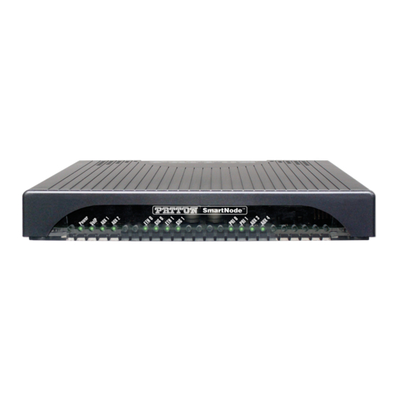
Page 18: Smartnode 5570 Front Panel
SmartNode 5570 User Manual 1 • General Information Figure 3. SmartNode 5570 front panel SmartNode 5570 Front Panel Figure 3 shows SmartNode 5570 LEDs, the LED definitions are listed in table 4 Table 4. SmartNode 5570 LED Definitions Description Note... -
Page 19: Applications Overview
Chapter 2 Applications Overview Chapter contents Introduction ................................20 Application—Edge Intelligence of Enterprise Communication ................20 How it works: ............................21 Application—Multi-service ISDN, Secure VoIP and Data Routing Solution ............21... -
Page 20: Introduction
2 • Applications Overview Introduction Patton’s SmartNode ESBRs deliver the features you need for advanced multiservice voice and data network applications. They combine high quality voice-over-IP with powerful quality of service routing functions to build professional, secure and reliable VoIP and data networks. This chapter describes typical applications for which this SmartNode is uniquely suited. -
Page 21: Application-Multi-Service Isdn, Secure Voip And Data Routing Solution
IP PBX or on the legacy PBX. Application—Multi-service ISDN, Secure VoIP and Data Routing Solution The SmartNode 5570 Series can be used to make and receive calls to and from the public ISDN network and internet telephony services on any ISDN PRI PBX (see Figure 5). -
Page 22: Smartnode Installation
IP related information .............................23 Software tools ..............................24 Power source ..............................24 Location and mounting requirements ......................24 Installing the Patton SmartNode ESBR .........................24 Placing the SmartNode ...........................24 Installing cables ...............................24 Connecting ISDN PBX and NT to the SmartNode’s ISDN PRI ports .............25 Connecting the 10/100/1000Base-T Ethernet LAN and WAN cables ............25... -
Page 23: Planning The Installation
24 to install the device. Site log Patton recommends that you maintain a site log to record all actions relevant to the system, if you do not already keep such a log. Site log entries should include information such as listed in Table 5. -
Page 24: Software Tools
If you suspect that your AC power is not reliable, for example if room lights flicker often or there is machinery with large motors nearby, have a qualified professional test the power. Patton recommends that you include an uninterruptible power supply (UPS) in the installation to ensure that VoIP service is not impaired if the power fails. -
Page 25: Connecting Isdn Pbx And Nt To The Smartnode's Isdn Pri Ports
Connecting the 10/100/1000Base-T Ethernet LAN and WAN cables The SmartNode 5570 has automatic MDX (auto-cross-over) detection and configuration on the Ethernet ports. Any of the two ports can be connected to a host or hub/switch with a straight-through wired cable. -
Page 26: Power Led
2 on page 16). There are no user-serviceable parts in the power supply section of the model SN5570. Contact Patton Electronics Technical Support at support@patton.com for more information CAUTION 2. Verify that the AC power cord included with your device is compatible with local standards. If it is not, refer to “Contacting Patton for Assistance”... -
Page 27: Initial Configuration
Chapter 4 Initial Configuration Chapter contents Introduction ................................28 Connecting the SmartNode to Your Laptop PC ....................28 Configure the Desired IP Address..........................29 Factory-default IP Settings ..........................29 Login ................................29 Changing the WAN IP address ........................29 Connecting the SmartNode to the Network ......................30 Loading the Configuration (optional)........................31 Additional Information... -
Page 28: Introduction
POTS line. CAUTION The SmartNode 5570 Series is equipped with Auto-MDX Ethernet ports, so you can use straight-through cables for host or hub/switch connections (see figure 7). Straight-through wired cable... -
Page 29: Configure The Desired Ip Address
SmartNode 5570 User Manual 4 • Initial Configuration Configure the Desired IP Address Factory-default IP Settings The factory default configuration for the Ethernet interface IP addresses and network masks are listed in Table 6. Both Ethernet interfaces are activated upon power-up. LAN interface ETH 0/1 (LAN) provides a default DHCP server, the WAN interface uses DHCP client to automatically assign the IP address and network mask. -
Page 30: Connecting The Smartnode To The Network
In general, the SmartNode will connect to the network via the WAN (ETH 0/0) port. This enables the Smart- Node to offer routing services to the PC hosts on LAN (ETH 0/1) port. The SmartNode 5570 Series is equipped with Auto-MDX Ethernet ports, so you can use straight through or crossover cables for host or hub/ switch connections. -
Page 31: Loading The Configuration (Optional)
The system is going down NOW Additional Information For detailed information about configuring and operating guidance, set up procedures, and troubleshooting, refer to the Trinity Release 3.5.x– Command Line Reference Guide available online at www.patton.com/man- uals. Loading the Configuration (optional) -
Page 32: Contacting Patton For Assistance
Chapter 5 Contacting Patton for Assistance Chapter contents Introduction ................................33 Contact information..............................33 Contacting Patton Technical Services for Free Support ...................33 Warranty Service and Returned Merchandise Authorizations (RMAs)..............33 Warranty coverage ............................33 Out-of-warranty service ..........................34 Returns for credit ............................34 Return for credit policy ..........................34... -
Page 33: Introduction
(RMA). Contact information Patton Electronics offers a wide array of free technical services. If you have questions about any of our other products we recommend you begin your search for answers by using our technical knowledge base. Here, we have gathered together many of the more commonly asked questions and compiled them into a searchable database to help you quickly solve your problems. -
Page 34: Rma Numbers
RMA#: xxxx 7622 Rickenbacker Dr. Gaithersburg, MD 20879-4773 USA Patton will ship the equipment back to you in the same manner you ship it to us. Patton will pay the return shipping costs. Warranty Service and Returned Merchandise Authorizations (RMAs) -
Page 35: Compliance Information
Appendix A Compliance Information Chapter contents Compliance ................................36 ................................36 Safety ................................36 Radio and TV interference ............................36 CE Declaration of Conformity ..........................36 Authorized European Representative ........................36 ISDN Compliance ..............................37... -
Page 36: Compliance
AC outlet (such that the computing equipment and receiver are on different branches). CE Declaration of Conformity Patton Electronics, Inc declares that this device is in compliance with the essential requirements and other pro- visions of Council Directive 1999/5/EC on the approximation of the laws of the member states relating to Radio and Telecommunication Terminal Equipment and the mutual recognition of their conformity. -
Page 37: Isdn Compliance
SmartNode 5570 User Manual A • Compliance Information ISDN Compliance The device is approved for connection to the public ISDN telecommunication network. For the ISDN connection to a carrier network, it shall be con- nected to a network termination device and not connected directly to an outside POTS line. -
Page 38: Specifications
Appendix B Specifications Chapter contents DSP..................................39 Voice Connectivity ..............................39 Data Connectivity ..............................39 Voice Processing (signalling dependent) ........................39 Fax and modem support............................40 Voice Signalling..............................40 Voice Routing—session router ..........................40 IP Services ................................41 Management .................................41 System ...................................41 Physical .................................41... -
Page 39: Dsp
SmartNode 5570 User Manual B • Specifications Note Refer to the software feature matrix for the most up-to-date specifications. Two 16 channel DSP Voice Connectivity 1 or 2 ISDN PRI ports, 4-wire RJ45 ports NT/TE configurable per port (layer 1 pin-out does not change) Life-line bypass relay between PRI 0/0 and PRI 0/1 ports (Depends on model;... -
Page 40: Fax And Modem Support
SmartNode 5570 User Manual B • Specifications Fax and modem support Automatic fax and modem detection Codec fallback for modem-bypass T.38 Fax-Relay (Gr. 3 Fax, 9.6 k, 14.4 K) G.711 Fax-Bypass Voice Signalling SIPv2, SIPv2 over TLS SIP call transfer, redirect... -
Page 41: Ip Services
SmartNode 5570 User Manual B • Specifications IP Services IPv4 router; IPv6 basic functionalities Programmable static routes and policy-routing ICMP redirect (RFC 792); Packet fragmentation DiffServe/ToS set or queue per header bits Packet Policing discards excess traffic DHCP client and server... - Page 42 Appendix C Cabling Chapter contents Introduction ................................43 Serial Console................................43 Ethernet ................................44 ISDN PRI (E1/T1) ...............................45...
-
Page 43: C Cabling
POTS line. CAUTION o le Serial Terminal A Patton Model 16F-561 RJ45 to DB-9 adapter is included with Note each SmartNode Series device Figure 9. Connecting a serial terminal Console Connection settings: •... -
Page 44: Ethernet
SmartNode 5570 User Manual C • Cabling Ethernet Ethernet devices (10/100/1000 Base-T) are connected to the SmartNode over a cable with RJ-45 plugs. All Ethernet ports on the SN5570 are Auto-MDX. Use any straight or crossover cable to a host, hubs, switches, PCs or other devices. -
Page 45: Isdn Pri (E1/T1)
SmartNode 5570 User Manual C • Cabling ISDN PRI (E1/T1) The E1/T1 PRI port 0/1 is usually connected to a PBX or switch—local exchange (LE). Type and pin outs of these devices vary depending on the manufacturer. In most cases, a straight-through RJ-45 to RJ-45 can be used to connect the PRI port 0/1 with a PBX. -
Page 46: Pri E1/T1 Cabling
SmartNode 5570 User Manual C • Cabling PSTN o l e PRI PBX SmartNode SmartNode PSTN NT Port 0/0 Port 0/1 RX Tip RX Tip TX Tip TX Tip TX Ring RX Ring TX Ring RX Ring TX Tip TX Tip... -
Page 47: Port Pin-Outs
Appendix D Port pin-outs Chapter contents Introduction ................................48 Console port................................48 Ethernet ................................48 ISDN PRI (E1/T1) Port Pin-outs..........................49... -
Page 48: Introduction
SmartNode 5570 User Manual D • Port pin-outs Introduction This section provides pin-out information for the ports of the SmartNode. Console port (N/C) (N/C) (N/C) Pins 1 & 3 are connected together Figure 14. EIA-561 (RJ-45 8-pin) port Note N/C means no internal electrical connection. -
Page 49: Isdn Pri (E1/T1) Port Pin-Outs
SmartNode 5570 User Manual D • Port pin-outs Table 8. 1000Base-T RJ-45 Socket Signal TRD0+ TRD0- TRD1+ TRD1- TRD2+ TRD2- TRD3+ TRD3- ISDN PRI (E1/T1) Port Pin-outs Table 9. Port 0/0 Signal RX_TIP RX_RING TX_TIP TX_RING Table 10. Port 0/1... -
Page 50: Smartnode 5570 Factory Configuration
Appendix E SmartNode 5570 Factory Configuration Chapter contents Introduction ................................51... -
Page 51: Introduction
SmartNode 5570 User Manual E • SmartNode 5570 Factory Configuration Introduction The factory configuration settings for SmartNode 5570 series can be obtained with the following command through the CLI; login: admin password: <Enter> 192.168.1.1>show config:shipping-config Please see Chapter 4, "Initial Configuration"... -
Page 52: F End User License Agreement
Appendix F End User License Agreement Chapter contents End User License Agreement ..........................53 1. Definitions ..............................53 2. Title ................................53 3. Term ................................53 4. Grant of License ............................53 5. Warranty ..............................53 6. Termination ..............................54 7. Other Licenses ............................54... -
Page 53: End User License Agreement
Program(s), even if Patton Electronics Company has been advised of the possibility of such damages. Because some states do not allow the exclusion or limitation of liability for consequential or incidental damages, the above limitation may not apply to you. -
Page 54: Termination
The End user may terminate this agreement by returning the Designated Equipment and destroying all copies of the licensed Program(s). Patton Electronics Company may terminate this Agreement should End User violate any of the provi- sions of section, “4. Grant of License”...
Need help?
Do you have a question about the SmartNode 5570 and is the answer not in the manual?
Questions and answers