
Related Manuals for SKC AirChek2000


Summary of Contents for SKC AirChek2000
-
Page 1: Operating Instructions
Operating Instructions SKC Inc. 863 Valley View Road Eighty Four, PA 15330 USA Form #37740 Rev 0806... -
Page 2: Table Of Contents
Table of Contents Description ..............................1 Performance Profi le ............................ 2 Battery Operation Installing the Battery Pack ........................4 Charging the Battery Pack ........................4 Battery Charge Level Indicator ......................5 Replacing the Battery Pack ......................... 5 Battery Eliminator ..........................6 Introduction Pump Display ............................ - Page 3 AirChek 2000 Quick Guide Operation Star Button Scrolls through run time data, display options, and sampling parameters during pump setup Up and Down Arrow Buttons Increase or decrease sampling parameters and toggle between display choices in setup Security Code Button Sequence Must be pressed within 10 seconds = press buttons individually of previous command...
-
Page 4: Description
2000 Soft ware and your PC to expand pump programmability and recordkeeping options. The result of extensive research and development, the AirChek 2000 Pump exemplifi es SKC’s commitment to quality and innovation in air sampling equipment. * U.S. Patent No. 5,892,160... -
Page 5: Performance Profi Le
Performance Profi le Flow Range: 1000 to 3250 ml/min (5 to 500 ml/min requires optional low fl ow adapter kit) Compensation Range: 3000 ml/min at 15 inches water back pressure 2000 ml/min at 30 inches water back pressure 1000 ml/min at 30 inches water back pressure Typical Back Pressure of Sampling Media (inches water) Flow Rate (L/min) Filter/Pore Size (μm) - Page 6 Intrinsic Safety: UL and cUL Listed Use only SKC-approved parts to ensure reliable performance and to maintain the UL Listing for intrinsic safety and the SKC warranty. Table 1. AirChek 2000 Run Time in Hours with NiCad Battery Following are typical run times achieved when using a fully charged Nickel- Cadmium (NiCad) battery pack.
-
Page 7: Battery Operation
Battery Operation Installing the Battery Pack To enhance battery life, SKC ships battery packs separate from the pump. Once installed, completely charge battery pack before operating pump. Carefully align the batt ery jack on the batt ery pack with the batt ery ter- minal on the bott om of the pump base plate and push the batt ery pack into place. -
Page 8: Battery Charge Level Indicator
SLEEP aft er the last run. Pump history will be lost if the batt ery pack or AC power (batt ery eliminator) is removed while the pump is running. SKC recommends that data be downloaded to a PC using DataTrac 2000 Soft ware prior to removal of the batt ery or power. -
Page 9: Battery Eliminator
Batt ery Batt ery pack jack Use of a repaired or rebuilt battery pack voids the SKC warranty and the UL Listing for intrinsic safety. Do not charge or operate the pump from the charger in hazardous locations! Use only an SKC-approved charger and battery pack designed for the AirChek 2000 Sample Pump to ensure reliable performance and to maintain the UL Listing for intrinsic safety and the SKC warranty. -
Page 10: Introduction
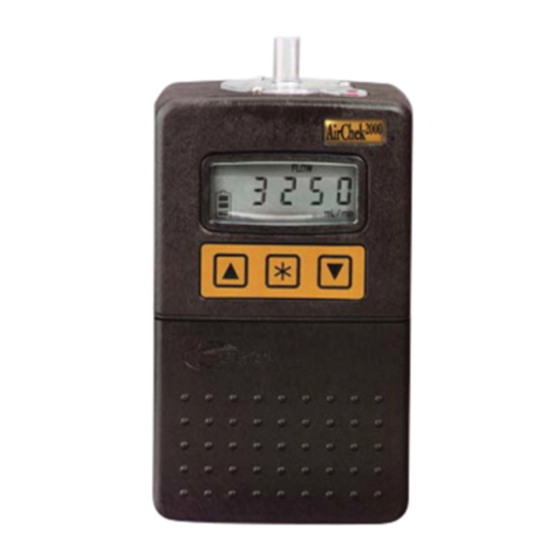
Introduction Pump Display AirChek 2000 LCD shown at 100% HOLD: Flashes when the pump is in HOLD mode (see page 9) SГ or S: Displayed when a sampling time is manually programmed into pump memory (see page 13) VOL: Volume of air pumped SET: Flashes when changing any setting CLr:... -
Page 11: Keypad Basics
Introduction Keypad Basics The AirChek 2000 Pump operates by pressing various butt on sequences on the keypad located on the front of the pump housing. Down arrow arrow Button button button AirChek 2000 Keypad shown at 100% Scrolls through run time data, display options, and sampling parameters during pump setup Increases values and toggles between options Decreases values and toggles between options... -
Page 12: Pump Operating Modes
Introduction Pump Operating Modes Pump is running; run time data is continuously updated in memory. The LCD shows real-time run time data. Press to scroll through the parameters. Run time and volume stored in memory will continue to accumulate unless reset (see page 12). -
Page 13: Setup
Setup Verifying Battery Charge Level The LCD displays an icon that shows the current batt ery charge level (see Batt ery Operation on page 5). A new batt ery should be fully charged before operation. Entering and Navigating the User Interface The AirChek 2000 User Interface features two levels: Level One—Set Up Flow Rate allows the user to change fl... -
Page 14: Using User Interface - Level Two
Setup Used during calibration with primary standard calibrator (not for use with CalChek feature). Press to increase to decrease fl ow adjustment until desired fl ow is indicated on an att ached primary standard. Press move to next parameter or the User Interface can be exited by continuing to press until End appears. -
Page 15: Resetting Run Time Data
Setup Time of day The hour will fl ash. Press to increase to decrease hour. Press advance to minutes. Once minutes are fl ashing, press to increase or decrease minutes. Press to move to next parameter. Press [ ] to reset accumulated run time and volume from pump memory to zero. -
Page 16: Setting Sampling Time
Setup Setting Sampling Time (S Г) Program the AirChek 2000 from the keypad to run STEL, TWA, or any other run time from 1 to 999 minutes*. AirChek 2000 sampling time may also be programmed from a PC using DataTrac 2000 Soft ware*. To program a sampling time using the pump keypad: With the pump running, press [ ] to place... -
Page 17: Setting A Delayed Start
Setup Setting a Delayed Start The Delayed Start feature is available in pump version 2.59 or higher. When sett ing the pump manually for sampling to begin within a 12-hour timeframe, follow this procedure: With the pump running, press [ ] to place the pump in HOLD and enter within 10 seconds. -
Page 18: Deleting A Sampling Time
Setup Deleting a Sampling Time (SГ) To delete a sampling time, enter User Interface Level Two and press the SГ SГ butt on to scroll to . Press until 00 appears. Press the butt on until End appears. Press [ Deleting a DataTrac 2000 Program If a DataTrac 2000 program is in pump memory, the PROG icon will appear in the upper left corner of the display. -
Page 19: Calibration
Calibration Flow Rate and Volume Display Flow rate displayed on the pump LCD is the fl ow to which the pump has been calibrated. To maintain fl ow as displayed, the pump automatically adjusts fl ow during sampling for changes in temperature and atmospheric pressure that may diff... - Page 20 Calibration Press until End appears on the LCD. Press [ ] to save fl ow sett ing and exit the User Interface. The pump will remain in RUN. Reset run time data (see page 12). Place pump in HOLD by pressing [ ].
-
Page 21: Calibrating Using Calchek
Press the right arrow to highlight Preferences; press Enter. d. Press the down arrow to navigate to Data Port. e. Press the left or right arrow to toggle to SKC. f. Press the down arrow to highlight Confi rm; press Enter. - Page 22 Calibration Insert the male end of the CalChek Communication Cable into the data port on the pump. Place the pump in HOLD by pressing [ ]. Press [ ] again to start the pump running, and enter the security code in sequence on the pump keypad within 10 seconds.
- Page 23 4 minutes. The operation calibrates each fl ow rate to a primary standard. It can also provide a record of calibration for maintenance and quality purposes if DataTrac 2000 Soft ware is used. SKC recommends that a full calibration be performed during pump maintenance and aft er non-factory repairs.
- Page 24 Calibration When calibration is completed, the pump will go to HOLD. If the calibration was successful, the pump LCD will revert to displaying pump run time as 0. If there was failure during the calibration process, an error code of E4[x] will appear (see CalChek Error Chart on page 22). Note: To remove a CalChek error code from the LCD, press Allow the pump to go to SLEEP mode to write calibration data to pump memory.
-
Page 25: Calchek Error Chart
Pump unable to achieve fl ow rate of Check pump’s fl ow tube to ensure 3000 ml/min possibly due to a blocked it is not blocked, or contact SKC fl ow tube or an air leak inside the pump. Technical Support. -
Page 26: Calibrating For Low Flow (5 To 500 Ml/Min) Sampling Applications
Calibration Calibrating for Low Flow (5 to 500 ml/min) Sampling Applications Using a Constant Pressure Controller (CPC) For use with CPC and Adjustable Low Flow Tube Holders. The Constant Pressure Controller (CPC) is an accessory that allows low fl ow (5 to 500 ml/min) applications. -
Page 27: Sampling (1000 To 3250 Ml/Min)
Sampling Sampling (1000 to 3250 ml/min Constant Flow) 1. Following calibration, replace representative sampling medium with a new unexposed medium. Ensure run time data has been reset (see page 12). Protect sample pump from weather when in use outdoors. For multiple-tube sampling, seal unused holder ports with unopened tubes. -
Page 28: Flow Fault
Sampling Long-duration Color Detector Tubes require a special tube cover that accommodates an in-line trap tube. The trap tube protects the pump from caustic fumes that are often released from detector tubes. Closely read all precautions when using these tubes. Failure to use the necessary traps will damage the pump and void the warranty. -
Page 29: Maintenance
Maintenance Replacing the Inlet Port Housing and Filter Remove the three screws that secure the inlet port housing to the top of the pump. Remove the inlet port housing and gasket. Remove the O-ring. Remove and discard the fi lter. Insert a new fi... -
Page 30: Service Policy
The Service Department will contact nonwarranty customers with an estimate before proceeding with repairs. SKC Inc. will accept for repair any SKC product that is not contaminated with hazardous materials. Products determined to be contaminated will be returned unserviced. -
Page 31: Accessories
Defender Primary Standard Calibrator, 50 to 5000 ml/min, includes batt ery, charger (100-240 V), cable, and soft ware 717-510M CalChek Communication Cable, required for CalChek feature 210-502 Chargers PowerFlex Charging System for SKC Personal Pumps 5-station, 100-240 V 223-1000 Single, 120 V 223-2000 Single, 100-240 V... - Page 32 Accessories Description Cat. No. Replacement Parts Batt ery Pack P20136 Batt ery Pack (CE marked; for Cat. No. 210-2002Ex) P21113 Belt Clip P20139 Case P20137 Case with interface for PC board in place P20137A Charging Jack P20145 Cover, Batt ery Pack P20144 Filter (inlet)/O-ring (3) P20140...
-
Page 33: Datatrac 2000 Software
Accessories DataTrac 2000 Software With the optional DataTrac 2000 Soft ware accessory, the AirChek 2000 is programmable using a PC. DataTrac 2000 simplifi es chain-of-custody reporting by allowing users the option of programming a complete running sequence, delayed start, timed stop, and intermitt ent sampling, all at diff... -
Page 35: Warranty
5. In the event of a defect, malfunction, or other failure of the instrument not caused by any misuse or damage to the instrument while in possession of the buyer, SKC Inc. will remedy the failure or defect without charge to the buyer. The remedy will consist of service or replace- ment of the instrument. -
Page 36: Index
Index Operating Indicators ......... 7 AC Charger ........4, 28 ADJ ..........7, 11 Accessories ..........28 CAL ........7, 11, 19 Activate Pump .......... 8 CLr ..........7, 12 ADJ Indicator ........7, 11 End ..........7, 12 Adjustable Low Flow Tube Holders ..23, 24, 28 ESC ..........
Need help?
Do you have a question about the AirChek2000 and is the answer not in the manual?
Questions and answers