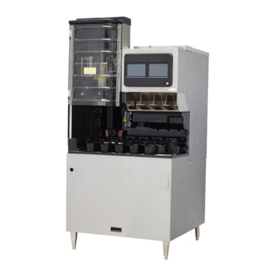
Cornelius ABS 2.0 Service Manual
Automated beverage system
Hide thumbs
Also See for ABS 2.0:
- Installation manual (66 pages) ,
- Service manual (64 pages) ,
- Operator's manual (64 pages)

Related Manuals for Cornelius ABS 2.0


Summary of Contents for Cornelius ABS 2.0
- Page 1 ABS 2.0 Service Manual Release Date: December 16, 2019 Publication Number: 621058590SER Revision Date: December 16, 2019 Revision: B Visit the Cornelius web site at www.cornelius.com for all your Literature needs.
- Page 2 Commercial Warranty. Cornelius will not be responsible for any repair, replacement or other service required by or loss or damage resulting from any of the following occurrences, including but not limited to, (1) other than normal and proper use and normal...
-
Page 3: Table Of Contents
Introduction to Abs 2.0 Programming ........ - Page 4 Syrup Mapping (Brand) ............31 Syrup Map .
- Page 5 Troubleshooting ..............51 Mechanical Issues .
- Page 6 -IV-...
-
Page 7: Safety Instructions
ABS 2.0 Service Manual SAFETY INSTRUCTIONS EAD AND OLLOW AFETY NSTRUCTIONS Safety Overview ALL SAFETY INSTRUCTIONS • ead and follow in this manual and any warning/caution labels on the unit (decals, labels or laminated cards). OSHA • ead and understand... -
Page 8: Qualified Service Personnel
ABS 2.0 Service Manual NOTE:T MUST NOT he dispenser is not designed for a wash-down environment and be placed in an area where a water jet could be used. UALIFIED ERVICE ERSONNEL WARNING: ALL WIRING nly trained and certified electrical, plumbing and refrigeration technicians are to service this unit. -
Page 9: General Information
When a beverage is ordered from the P.O.S. register, the ABS 2.0 automatically drops a cup, fills it with ice and dispenses the correct amount and type of any syrup-based beverage. The finished drink is then moved by the carousel to the pick-up station and the drink description is displayed on the touchscreen. -
Page 10: Features
629097799 ICEMAKER ADAPTER ABS 2.0 HOSHIZAKI 629097800 PRE - CHILLER 120V /60Hz 560000270 PRE - CHILLER 230V /50Hz 560002730 UPPORTED AKER Table 4. List of ice maker compatible with ABS 2.0 SL NO. BRAND MODEL MANITOWOC IB0620C-161 MANITOWOC IB0820C-161 MANITOWOC... -
Page 11: Unit Drawing
ABS 2.0 Service Manual UNIT DRAWING Figure 1. Dimension Unit in [mm]. © 2019, Cornelius Inc. - 5 - Publication Number: 621058590SER... -
Page 12: E-Box Configuration
ABS 2.0 Service Manual E-BOX CONFIGURATION WARNING: isconnect power to the unit before accessing the -box. [4] Agitator motor capacitor [3] 30V DC Power Supply for Valve Bank. [5] 3A-30V [6] AC Power Inlet [5] 4A-24V [5] 4A-12V [4] Carousel motor capacitor [4] Turret motor capacitor Figure 2. -
Page 13: Initializing And Self Test
NITIALIZING Turn ON the ABS 2.0 unit at the ABS 2.0 ON/OFF switch located on the left top corner of the stand. During the power-up sequence the Self Test and Initializing messages will be displayed as each test is being made. When the tests are complete the final message will be displayed. -
Page 14: Manual Mode Operation
In the MANUAL mode, POS data is updated and ALARM messages are displayed. In MANUAL mode the highlight flashes to alert operator that the ABS 2.0 unit is in the MANUAL mode. While in the MANUAL mode, POS drink orders continue to be received and placed in the order buffer. -
Page 15: Automatic Mode Operation
UTOMATIC PERATION In automatic mode the beverage dispense automatically from the input of POS system. By default ABS 2.0 System is setup to Automatic operation mode. If alarm conditions are present (but previously acknowledged) the ABS 2.0 status will indicate Warning. While the Warning status is present. -
Page 16: Semi-Automatic Drink Order Entry
ABS 2.0 Service Manual AUTOMATIC RINK RDER NTRY Manual order entry can be made without entering the drink at the POS. This is normally done to correct an error in entry, to pour a replacement drink or to accommodate a customer special request. -
Page 17: To Service
Default Settings/Restoring Settings The ABS 2.0 system is factory set to satisfy the majority of all installations. Do not make any adjustments until you are sure the factory settings will not satisfy the store requirements. Touch Panel Layout & Explanation... -
Page 18: Display Explanation
6. Alarm, cleaning due or past due. 7. Order - Current example. -L (Large), Regular (Ice type) -Order (ABS 2.0 = Semi Auto or Order Number) 8. Finished Drinks 1-6, left to right, Coke is Position one. 9. Flush - CW has flushed the Nozzle. -
Page 19: Entering The Technician Screen
ABS 2.0 Service Manual the T NTERING ECHNICIAN CREEN Table 6. Step Action Figure 1. Select the Menu as shown in Figure 11. Figure 11. 3. Select the Technician Icon as shown Figure 12. Figure 12. Close the Clear the 5. -
Page 20: Carousel Assembly / Splash Panel Removal
ABS 2.0 Service Manual CAROUSEL ASSEMBLY / SPLASH PANEL REMOVAL AROUSEL SSEMBLY EMOVAL Table 7. Step Action Figure Select manual button from start screen as shown Figure 15. Figure 15. Remove cover by loosening the 3 thumb screws and lifting it upwards. -
Page 21: Splash Panel Removal
ABS 2.0 Service Manual PLASH ANEL EMOVAL Table 8. Step Action Figure Open turret door (optional remove turret assembly) and remove the five screws holding the splash panel, as shown in Figure 19 and pull the panel forward and down to remove it. -
Page 22: Nozzle Diffuser Removal
ABS 2.0 Service Manual NOZZLE DIFFUSER REMOVAL NOTE:Diffuser cleaning or sanitizing is recommended twice weekly. Table 9. Step Action Figure Turn nozzle clockwise (left), Than pull down, the diffuser will stay in position (it is keyed only, fits one way). - Page 23 ABS 2.0 Service Manual Table 9. (Continued) Step Action Figure This side up – you should be able to feel the raised edges of the seal holes when you re- insert into nozzle. Figure 25. With the Seal side up, align the notches in the Diffuser with the ribs on Nozzle Base.
- Page 24 ABS 2.0 Service Manual Table 9. (Continued) Step Action Figure If the Nozzle is installed on an angle, it is Incor- rectly installed. An incorrectly installed nozzle will have decreased performance (dripping, excess carryover, etc). Figure 30. Publication Number: 621058590SER - 18 - ©...
-
Page 25: Multi-Flavor Valve Configuration
ABS 2.0 Service Manual MULTI-FLAVOR VALVE CONFIGURATION WARNING: Disconnect power to the unit before accessing the MFV valve. Table 10. Step Action Figure Each round shutoff (Spindle) needs to be pressed towards down as shown as in Figure 31 to allow fluid to flow past the back-block into the valves. -
Page 26: Disassembly Of An Mfv Valve Module
ABS 2.0 Service Manual MFV V ISASSEMBLY ALVE ODULE Table 11. Figure Step Action Once the valve module is removed, pull the locking clip upwards and remove. Figure 35. Pull up and rotate valve upwards of bracket to remove from the module. -
Page 27: Reassembly Of Mfv Valve
ABS 2.0 Service Manual MFV V EASSEMBLY OF ALVE Table 12. Step Action Figure Place valve into the valve carrier. NOTE: Use only Dow III or equivalent on all O-rings Figure 38. Start the solenoid at a 45 deg. angle and... - Page 28 ABS 2.0 Service Manual Table 12. Step Action Figure The valve is back in position and ready to insert stainless steel locking clip. Figure 41. • Place valve on the backblock. (make sure wires are not pinched) • Push up on dovetail to lock valve.
-
Page 29: Ice Chute Cover Removal / Replace
ABS 2.0 Service Manual ICE CHUTE COVER REMOVAL / REPLACE Table 13. Step Action Figure Select manual button from start screen as shown in Figure 44. Figure 44. Lift chute upward to release the locking tabs as shown in Figure 45 Figure 45. - Page 30 ABS 2.0 Service Manual Table 13. Step Action Figure Press downward to replace the Ice chute cover. and ensure the sensor working fine. Figure 47. Publication Number: 621058590SER - 24 - © 2019, Cornelius Inc.
-
Page 31: Water & Syrup Line Connections
ABS 2.0 Service Manual & S ATER YRUP ONNECTIONS The standard unit supports the following: • 2-water lines from carbonator/chiller/ Recirculation system. • 1-water line for non-carbonated drinks. • 8-Syrup lines. the U ONNECTING RODUCT TO The unit must have a product supply connected to each in let on the cold-plate. Refer to the cold-plate diagram below Figure 48. -
Page 32: Set Flow Rate And Valve Ratio
ABS 2.0 Service Manual ATE AND ALVE ATIO NOTE: Cold plate should have ice on it and should be cold. Remove the carousel assembly to allow easy access to the area under the valve for the ratio cup. Refer Table 8. for accessing the MFV valves in the unit. -
Page 33: Adjusting Water Flow Rate
ATER Overview: The ABS 2.0 uses 2 MFV water valves for both carbonated water (CW1 & CW2) and plain water (PW1 & PW2). Each valve module has a high-flow orifice and a low-flow orifice. The high-flow orifice provides approximately 75% and the low-flow orifice provides approximately 25% of the total flow rate. -
Page 34: Set Overall Water Valve
ATER ALVE NOTE: This is the step that adjusts the pour times of all beverages dispensed from the ABS 2.0. If this step is not completed, then drinks will either over- or under-pour depending on the flow rate adjustment of the valves Table 15. -
Page 35: Troubleshooting For Water Valve
ABS 2.0 Service Manual ROUBLESHOOTING FOR WATER VALVE • If drinks overfill, this means the dispense times are too high for the flow rate that the valves have been adjusted to. Repeat the above steps and increase volume entered. This will shorten the dispense time prevent overfilling. -
Page 36: U.s.a. Follow The Procedure Below
ABS 2.0 Service Manual U.S.A. Follow The Procedure Below: 1. Hold the ratio cup water compartment below the valve and select the Plain Water button if adjusting a non-car- bonated drink or the carbonated water button if adjusting a carbonated water drink. -
Page 37: Syrup Mapping (Brand)
ABS 2.0 Service Manual YRUP APPING BRAND Syrup Map The table below, shows all the brand names that are resident in the ABS 2.0 system. The listed brands are the default brands position in units. Table 17. DEFAULT SETTINGS POS PROGRAMMING DATA... -
Page 38: Brand Mapping Explanation
(Figure 58.). When this has been done, the ABS 2.0 system will then display Diet Coke as the flavor dispensed on valve #2. Figure 58.Syrup Map Explanation 1 Drink List Create a drink list showing the exact position of each drink in the ABS 2.0 system give to GM or keep at the unit (Behind screen) Table 18. POS ID Brand / Aust. -
Page 39: Mapping - Second Step
ABS 2.0 Service Manual Mapping – Second Step Table 19. Step Action Figure From unit setup Menu select the Map Brands to Valves as shown in Figure 59. Figure 59. Brand mapping menu as shown in Figure Figure 60. Select the Valve’s as shown in Figure 61. -
Page 40: Drink List
ABS 2.0 Service Manual Table 19. (Continued) Select the brand to assign the valve by scroll the brand’s using of up/down arrow as shown in Figure 62. Figure 62. Save the Mapping and back to home or pre- vious menu Figure 63. -
Page 41: Adjustment Ice
ABS 2.0 Service Manual DJUSTMENT The carousel assembly must be installed before beginning this procedure. Table 20. Step Action Figure Place the measuring cup under the ice dispenser.Select the “Ice Dispense Cali- bration” Icon from the Unit setup menu as shown in Figure 64. -
Page 42: Saving The Set-Up
ABS 2.0 Service Manual AVING THE Select preferences in respective set up and press “SAVE” icon shown in Figure 67. to save the setting of the menu Figure 67. and W LARM ARNING ESSAGES Follow the steps to alarm logging Table 21. - Page 43 ABS 2.0 Service Manual Table 21. Step Action Figure current status of the messages show at right side as shown in Figure 71. Figure 71. © 2019, Cornelius Inc. - 37 - Publication Number: 621058590SER...
-
Page 44: Cup Carousel
ABS 2.0 Service Manual CUP CAROUSEL ESCRIPTION PERATION The carousel is controlled by the Motion Control Board. When a drink order is placed at the POS the correct cup is pulled and placed into the carousel. The carousel is then rotated clockwise by the gear motor to move the cup to the ice drop position based on the following information: •... -
Page 45: Last Cup Sensor
If, for example, there were cups at Cup Serve Positions; “A” and “B”, and the cup at Point “A” was removed the carousel would rotate one space until the cup that was at Point “B” moves to Point “A”, then the ABS 2.0 would be stopped again. -
Page 46: Carousel Drive Alignment
ABS 2.0 Service Manual AROUSEL RIVE LIGNMENT When installing the carousel the carousel belt may be rotated to align the Drive Pin and the Drive Socket. The Drive Pin on the carousel must engage the Drive Socket on the gear motor or the carousel is not properly installed and will not operate. -
Page 47: Cup Picker
ESCRIPTION PERATION The Cup Puller is activated by a command from the POS to the ABS 2.0. When a drink order is placed at the POS, the correct cup is pulled and placed into the carousel. The cup puller consists of, two cup grabber arms actuated by a pneumatic cylinder, an elevating mechanism operated by a pneumatic cylinder, and two guide rods. -
Page 48: Empty Cup Tube Sensor
This will cause a “Empty Cup Tube” message to be sent. See the sequence of events above for a full description of this sensor. CAUTION: Do Not attempt any repair until the ABS 2.0 unit has been shut down and the air/CO has been shut OFF. Serious injury could occur if the cup grabber activates during repair. -
Page 49: Cup Turret System
24” drive shaft, shrouded with a protective sleeve. The cup turret is activated by a command from the POS to the ABS 2.0. The cup turret rotates so that the correct cup size is at the cup drop position. The cup is then pulled and placed into the carousel. -
Page 50: Cup Holders Installation
ABS 2.0 Service Manual OLDERS NSTALLATION Table 22. Step Action Figure Each cup dispenser has two mounting holes as shown in Figure 76. Figure 76. Attach the cup tube clip to the turret by fasten- ing four screws as shown Figure 77. - Page 51 ABS 2.0 Service Manual Table 22. (Continued) Pivot the base to align the second mounting hole on cup holder with the top hole and fix in place with a screw as shown in Figure 79. Figure 79. Load one complete sleeve by pushing through bottom opening and gradually lower the hand until the cups are supported.
-
Page 52: Turret Drive Assembly
& M URRET OTOR The gear box and motor are replaceable and are accessible from top side under the black cover of the ABS 2.0. Four bolts attach them to the Gear/Motor bracket. NCODER The alignment disk, attached with three screws to the shaft coupler, interfaces with the turret position sensor and notifies the Motion Control Board of which cup tube is at the extract position. -
Page 53: Ice Chute Assembly
ABS 2.0 Service Manual ICE CHUTE ASSEMBLY ESCRIPTION The ice gate is a pneumatically operated “gate” that is controlled by the Beverage Interface Board. The time the gate is open is very precise and determines the portion of ice dispensed. The gate opens and closes under pneumatic pressure[35psi(.24Mpa)]. -
Page 54: Dispensing Valve
ABS 2.0 Service Manual DISPENSING VALVE ALVE ESCRIPTION The dispensing valve is located behind the splash panel and is made up of 3 blocks of 4 valves/solenoids. The blocks are mounted to the outlet of the cold-plate. The outlets of the valves are plumbed to the nozzle. The front view is shown below. -
Page 55: Diagnostics
ABS 2.0 Service Manual DIAGNOSTICS The Diagnostics menu is used to pre-test and adjust the function of ABS 2.0 unit for Sensor input and output or Automate moving assembly. It’s run while servicing the assembly.It is also ensure the Unit function working properly. - Page 56 ABS 2.0 Service Manual Table 24. (Continued) Step Action Figure A. If select the top button on the menu the Gripper arm move to the position and the sensor highlight in green as shown in Figure 87. If the position is not correct the sensor will Highlight in red.(the sensor...
-
Page 57: Troubleshooting
ABS 2.0 Service Manual TROUBLESHOOTING WARNING: nly trained and certified electrical, plumbing and refrigeration technicians should service this unit. ALL WIRING AND PLUMBING MUST CONFORM TO NATIONAL AND LOCAL CODES. FAIL- URE TO COMPLY COULD RESULT IN SERIOUS INJURY, DEATH OR EQUIPMENT DAMAGE... -
Page 58: Mechanical Issues
ABS 2.0 Service Manual Table 25. (Continued) Message Explanation Correction A. Could be caused by excessively long A. Increase line size to 1/2”. runs (over 40 ft.) of 3/8” (9.525 mm) B. Add water pressure booster pump. water supply line. -
Page 59: Beverage / Ice Related Issues
ABS 2.0 Service Manual Table 26. Message Explanation Correction Change CO cylinder or have bulk tank supply is low or empty or Air com- AIR OR CO LOW OR OUT refilled. pressor not operating Check cause not operating and repair. -
Page 60: Pos Related Issues
Make sure that the order in which the brands and size are the same in brand ABS UNIT IS DISPENSING Setup and size Setup in the Drink dispenser as it is on the ABS 2.0 System. THE WRONG SIZE OR Coca-Cola will provide the brand Position Guide for POS programming. -
Page 61: Schematics
ABS 2.0 Service Manual SCHEMATICS IRING IAGRAM A C TL B CTL DOOR LOCK PKR CTL TURRET SENSOR W HT O RG Y EL RE D RE D CO2 OUT STILL OU T CHUTE LAST CUP FIRST CUP SYRUP OUT CARB OUT... -
Page 62: B Ctla Ctl
ABS 2.0 Service Manual A CTL B CTL DOOR LOCK PKR CTL TURRET SENSOR W HT O RG Y EL RE D RE D CO2 OUT STILL OU T LAST CUP CHUTE FIRST CUP SYRUP OUT CARB OUT LOW ICE... -
Page 63: Plumbing Diagram (Air/Co 2 )
ABS 2.0 Service Manual PLUMBING DIAGRAM (AIR/CO AIR/CO2 PICKER POSITIONS EXHAUST PRESSURE EXHAUST FILTER & REGULATOR UNIT 560000391 EXHAUST PRESSURE PRESSURE MIDDLE: .358 Mpa (52PSI) PRESSURE EXHAUST PRESSURE DOWN: 1B PRESSURE 1A EXHAUST OPEN: 1B EXHAUST 1A PRESSURE CLOSE: Ø0.419mm (Ø... - Page 64 ABS 2.0 Service Manual Publication Number: 621058590SER - 58 - © 2019, Cornelius Inc.
- Page 65 ABS 2.0 Service Manual © 2019, Cornelius Inc. - 59 - Publication Number: 621058590SER...
- Page 66 ABS 2.0 Service Manual Publication Number: 621058590SER - 60 - © 2019, Cornelius Inc.
- Page 68 Cornelius Inc. www.cornelius.com...
Need help?
Do you have a question about the ABS 2.0 and is the answer not in the manual?
Questions and answers