
Related Manuals for THORLABS PM300E


Summary of Contents for THORLABS PM300E
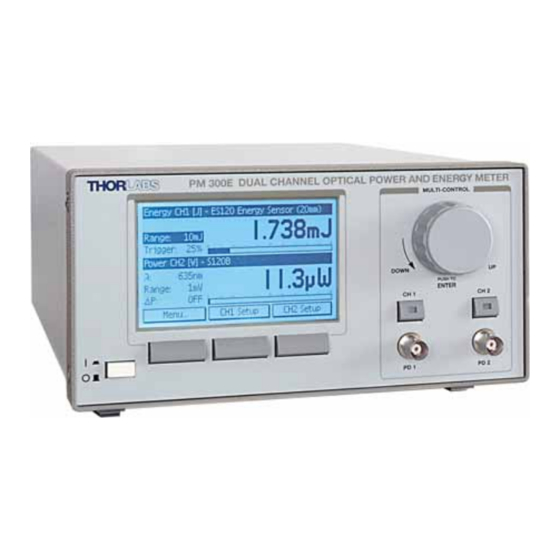
- Page 1 Operation Manual Thorlabs Instrumentation Optical Power and Energy Meter PM300E 2007...
- Page 2 Version: 16555-D02 REV A Date: 20.11.2007 © Copyright 2007, Thorlabs, Germany...
-
Page 3: Table Of Contents
2.2 Preparation 2.3 Physical Overview 2.3.1 Operating Elements in the Front Panel 2.3.2 Operating Elements in the Rear Panel 2.3.3 Main Screens Operating the PM300E 3.1 Sensor independent Operation and Settings 3.1.1 Navigating the Menus 3.1.2 System Settings 3.1.3 Readout Configuration 3.1.4... - Page 4 3.7 Miscellaneous Analog Output 3.8 Statistics Mode 3.9 Chart Mode (Power Sensors) 3.10 Histogram Mode (Energy Sensors) 3.11 System Configuration Computer Interface 4.1 Connecting a Computer 4.2 PM300E Utility Software 4.3 Firmware Update 4.4 Command Reference 4.4.1 Common IEEE488.2 Commands 4.4.2 Measurement Commands 4.4.3...
- Page 5 7.7 Selection of Thorlabs Photo-Diodes 7.7.1 SM05PD Series 7.7.2 SM1PD Series 7.7.3 IS200 Integrating Sphere Series 7.7.4 Calibrated Photodiodes 7.8 Thorlabs ‘End of Life’ policy (WEEE) 7.8.1 Waste treatment on your own responsibility 7.8.2 Ecological background 7.9 List of figures 7.10 Addresses...
- Page 6 We and our international partners are looking forward to hearing from you. Thorlabs This part of the instruction manual contains every specific information on the PM300E optical power meter. A general description is followed by explanations of how to operate the unit manually. You will also find information about a simple remote control of the unit.
-
Page 7: General Information
1.1 Safety 1 General Information The PM300E Benchtop Optical Power and Energy Meter is designed to measure the optical power of laser light or other monochromatic or near monochromatic light sources and the energy of pulsed light sources. The dual channel design and compatibility to all Thorlabs Photodiode, Thermal,... -
Page 8: Safety
All statements regarding safety of operation and technical data in this instruction manual will only apply when the unit is operated correctly. Before applying power to your PM300E system, make sure that the protective conductor of the 3 conductor mains power cord is correctly... - Page 9 1.1 Safety Attention Mobile telephones, cellular phones or other radio transmitters are not to be used within the range of three meters of this unit since the electromagnetic field intensity may then exceed the maximum allowed disturbance values according to IEC 61326-1. This product has been tested and found to comply with the limits according to IEC 61326-1 for using connection cables shorter than 3 meters (9.8 feet).
- Page 10 ▪ Consult the dealer or an experienced radio/T.V. technician for help. Thorlabs GmbH is not responsible for any radio television interfer- ence caused by modifications of this equipment or the substitution or attachment of connecting cables and equipment other than those specified by Thorlabs GmbH.
-
Page 11: Ordering Codes And Accessories
1.2 Ordering Codes and Accessories 1.2 Ordering Codes and Accessories Ordering code Short description PM300E PM300E Dual Channel Benchtop Power Meter S120B Si Photodiode Optical Sensor, 400 - 1100nm, 50nW-50mW S120UV Si Photodiode Optical Sensor, 200 - 1100nm, 50nW – 50mW... -
Page 12: Getting Started
Prior to starting operation with the PM300E optical power meter, check if the line voltage set with the voltage selector at the rear panel agrees with your local supply and if the appropriate fuses are inserted. -
Page 13: Physical Overview
2.3 Physical Overview Via the banana connector jack of the chassis ground the external optical build-up can be connected to ground potential, if required. 2.3 Physical Overview 2.3.1 Operating Elements in the Front Panel Control Knob Power Switch Soft Keys Display Selector Photodiode Inputs CH1;... -
Page 14: Operating Elements In The Rear Panel
2.3 Physical Overview 2.3.2 Operating Elements in the Rear Panel Ground Connector Trigger Input (4mm banana) (BNC) USB Interface Misc. Out: Analog Outputs Mains Connector Connector Programmable CH1, CH2 Including line switch (Type ‘B’) Analog Output (BNC) and fuses (BNC) CH2 Sensor Connector CH1 Sensor Connector (SubD 9p fem.) -
Page 15: Main Screens
2.3 Physical Overview 2.3.3 Main Screens Channel Header with Display, Channel and Sensor Information Main Display CH1 Main Display CH2 Soft Keys Figure 3 Dual Channel Screen Directly Main Display accessible Settings Sub Display Bargraph (Main Display) Figure 4 Single Channel Screen (CH1) Figure 5 Power Trend Graph Channel 2... - Page 16 2.3 Physical Overview Figure 6 Power Statistics Screen Channel 2 Figure 7 Energy Statistics Screen Channel 2 Figure 8 Energy Histogram Channel 1...
-
Page 17: Operating The Pm300E
3.1 Sensor independent Operation and Settings 3.1.1 Navigating the Menus The PM300E is controlled by three display/menu dependent soft buttons below the graphics display and/or the multi-control knob including a push button with an Edit/Enter functionality. All displays have directly accessible settings by navigating and clicking with the Multi-Control knob. -
Page 18: Readout Configuration
3.1 Sensor independent Operation and Settings Configures the measurement value, sensitivity and offset of the programmable analog output (MISC OUT). • System Configuration Contains hardware adjustments like LCD illumination, 50/60Hz line filter setting and system information. 3.1.3 Readout Configuration The main display can be configured in terms of units of measure and also with mathematical functions between the two channels. -
Page 19: Range Setting
CH1-CH2, CH2-CH1 [W] 3.1.4 Range Setting The PM300E provides sensor dependent up to six power corresponding current and up to three power corresponding voltage measurement ranges that can be selected in manual-range or auto-range mode; and four energy corresponding voltage measurement ranges that can be selected in manual mode. -
Page 20: Relative Power Measurement
3.1 Sensor independent Operation and Settings 3.1.5 Relative Power Measurement This feature can be used to observe power drifts, adjust power to a certain level, or quickly subtract ambient light. Navigating to the direct access ‘∆P’ setting and clicking the Multi-Control knob toggles between relative and absolute power measurement. -
Page 21: Trigger Input
3.1 Sensor independent Operation and Settings 3.1.7 Trigger Input For power and energy measurements the PM300E has two trigger modes that can be selected for each channel in the CHx Setup under <Trigger Source>: Figure 12 Trigger Input Depending on the connected sensor the selected trigger source has the function shown in the table below. -
Page 22: Operation With A Photodiode Power Sensor
3.2 Operation with a Photodiode Power Sensor 3.2 Operation with a Photodiode Power Sensor Photodiode sensors of the Thorlabs S1xx series can be connected to each of the Sub-D jacks in the rear panel. The sensor will be recognized immediately after plugging. -
Page 23: Wavelength Correction
When measuring very small power levels this dark current can have an influence on the measurement result and must be compensated by the dark current adjustment. The function the PM300E delivers by entering the <CHx Setup> and navigating to the ‘Dark Current’ menu can also be used to subtract ambient light. -
Page 24: Bandwidth Setting
3.2 Operation with a Photodiode Power Sensor the smallest possible measurement range, measure the photo current and from now on take in account this value when calculating the power reading. Press <Exit> to return to the measurement screen. Figure 15 Dark Current Adjustment 3.2.3 Bandwidth Setting The analog bandwidth setting mainly influences the analog outputs to for example... -
Page 25: Operation With A Thermal Power Sensor
3.3 Operation with a Thermal Power Sensor 3.3 Operation with a Thermal Power Sensor Thermal sensors of the Thorlabs S2xx series can be connected to both CH1 and CH2 Sub-D jacks in the rear panel. The sensor will be recognized immediately after plugging. -
Page 26: Readout Acceleration
2 and 6 with a wire connection see sensor pin-out chapter 7.4 The PM300E will recognize a ‘Thermal Head Adapter’ with the possibility to read the measurement value in Volts or by entering a responsivity factor in V/W also as power... -
Page 27: Operating With A Pyroelectric Energy Sensor
With pyroelectric sensors the PM300E measures laser pulse energy of single and continuously repeating laser pulses (short pulse). Pyroelectric sensors of the Thorlabs ES1xx and ES2xx series can be connected to both CH1 and CH2 Sub-D jacks in the rear panel. The sensor will be recognized immediately after plugging. -
Page 28: Trigger Level
The trigger level can be adjusted between 1% and 70% of each energy range. Only pulses that are higher than the adjusted trigger level are recognized by the PM300E. The trigger level should be set between the noise level and the expected pulse height. -
Page 29: Custom Pyroelectric Sensors
3.4 Operating with a Pyroelectric Energy Sensor 3.4.3 Custom Pyroelectric Sensors The PM300E is capable to handle any pyroelectric detector with a special Sub- D to BNC adapter. Instead of the wavelength correction a Sensitivity menu will appear, where the sensitivity can be entered in V/J. -
Page 30: Power Measurement With Photodiodes
3.5 Power Measurement with Photodiodes 3.5 Power Measurement with Photodiodes Common photo-diodes or Thorlabs packaged photo-diodes of the SM05PD and SM1PD series can be connected to the two BNC jacks in the front panel. The BNC input is automatically active when no power meter sensor or adapter is connected to the related DB9 connector in the rear. -
Page 31: Bias
3.6 Analog Outputs 3.5.3 Bias A bias voltage from 0 to 10V can be applied to the photodiode. The voltage can be set in the <CHx Setup> under the ‘Bias Voltage’ menu. To switch the bias voltage navigate to the ‘Bias’ menu in the channel screens or in the channel setups. Attention Proof for a positive current reading prior to applying a bias voltage. -
Page 32: Miscellaneous Analog Output
3.7 Miscellaneous Analog Output 3.7 Miscellaneous Analog Output The MISC OUT is a programmable analog output that provides a voltage from -10V to +10V depending on the selected function. The voltage from this output can be configured in the ‘Misc Output Configuration’ in the main ‘Menu’ in terms of each possible power or energy read out (Measurement Value), gain (Output Sensitivity) and offset (Offset Voltage). -
Page 33: Statistics Mode
3.8 Statistics Mode 3.8 Statistics Mode The statistics mode can be accessed by toggling the ‘CHx Display’ button (right soft key) in a Single Channel screen. Three modes can be selected to acquire the measurement data: Continuous: Data will be acquired until the <Stop> button is pressed Time: Data will be acquired for a pre-selected time Samples:... -
Page 34: Histogram Mode (Energy Sensors)
3.10 Histogram Mode (Energy Sensors) The time base can be set from 100ms/div up to 1h/div so that up to 16 hours can be monitored on one screen. This screen can be accessed only with power sensors or photodiodes. 3.10 Histogram Mode (Energy Sensors) The chart mode can be accessed by toggling the ‘CHx Display’... -
Page 35: System Configuration
3.11 System Configuration 3.11 System Configuration The system configuration menu contains the following items: Item Value Description LCD Brightness 0 – 100% Sets Backlight of the LCD Sound ON/OFF Local Operation/ ------- Shows Remote State Remote Operation Go To Local Line Filter 50Hz / 60Hz Sets line filter to the mains conditions to suppress unwanted aliasing effects in the read... -
Page 36: Computer Interface
Administrator privileges on the PC which you are perform- ing the install. Prior to connecting the PM300E with the PC, please insert the CD that shipped with the instrument and install the PM300E drivers. When the following message appears... - Page 37 The source code of the application is included on the CD and can be used to build own applications or to modify the utility program to customer requirements. After launching the PM300E utility program it will automatically screen for connected PM300 series devices. Select the desired PM300 device and press o.k.
- Page 38 4.2 PM300E Utility Software...
-
Page 39: Firmware Update
Firmware upgrades can be done by the user via the USB interface. Therefore install the DFU (device firmware upgrade) wizard from the distribution CD. Connect the PM300E to an USB port of your PC and launch the DFU wizard from the start bar. Follow the wizard instructions. -
Page 40: Command Reference
4.4 Command Reference 4.4 Command Reference 4.4.1 Common IEEE488.2 Commands The device supports several IEEE488.2 common commands and queries. Additional descriptive information may be found in the IEEE488.2-1992-§10 standard. 4.4.1.1 Command List Command Description *IDN? Identification query. (IEEE488.2-1992-§10.14) *TST? Selftest query. (IEEE488.2-1992-§10.38) *OPC Operation complete command. - Page 41 4.4 Command Reference 4.4.1.2.2 Selftest Query Command format: *TST? Response format: <NR1 NUMERIC RESPONSE DATA> Description: Selftest query (see also IEEE488.2-1992-§10.38 and chapter ‘Selftest Results’ in this document). A return value of ‘0’ means success. 4.4.1.2.3 Operation Complete Command Command format: *OPC Sets the ‘OPC’...
- Page 42 4.4 Command Reference Response format: <NR1 NUMERIC RESPONSE DATA> Description: Queries the device’s Service Request Enable Register (see also IEEE488.2- 1992-§10.35 and chapter ‘Status Reporting’ in this document). 4.4.1.2.9 Read Status Byte Query Command format: *STB? Response format: <NR1 NUMERIC RESPONSE DATA> Description: Queries the device’s Status Byte (see also IEEE488.2-1992-§10.36 and chapter ‘Status Reporting’...
-
Page 43: Measurement Commands
Fetch the channel 1/2 measured photodiode thermopile voltage value [V] :FETCH:UPY[1,2]:VAL? Fetch the channel 1/2 measured pyroelectric adaptor voltage value [V] :FETCH:POW[1,2]:VAL? Fetch the channel 1/2 measured optical power [W] (PM300E only) :FETCH:ENERGY[1,2]:VAL? Fetch the channel 1/2 measured pulse energy value [J] :FETCH:FREP[1,2]:VAL? - Page 44 Response format: Description: Queries the channel 1/2 measured photodiode current in Ampere [A]. Note: If an overflow occurs the value ‘+Inf’ or ‘-Inf’ is returned. 4.4.2.2.5 Voltage Query (channel 2 PM300E only) Command format: :VOLT[1,2]:VAL? Thermopile voltage <NR3 NUMERIC RESPONSE DATA>...
- Page 45 4.4 Command Reference 4.4.2.2.6 Pyroelectric Adapter Voltage Query (PM300E only) Command syntax: :UPY[1,2]:VAL? Pyroelectric adaptor voltage <NR3 NUMERIC RESPONSE DATA> Response syntax: Description: Queries the channel 1/2 measured pyroelectric adapter voltage in Volt [V]. Note: If an overflow occurs the value ‘+Inf’ or ‘-Inf’ is returned.
- Page 46 Description: Initiates a new measurement at the selected channel. The status of a measurement can be checked with the :MEAS:CHECK[1,2]? command (see below). 4.4.2.2.15 Abort a running measurement (PM300E only) Command syntax: :MEAS:ABORT[1,2] Description: Cancels a running measurement at the selected channel.
- Page 47 Queries the channel 1/2 measured thermopile voltage value in Volt [V] of the measurement started by :MEAS:INIT[1,2]. Note: If an overflow occurs the value ‘+Inf’ or ‘-Inf’ is returned. 4.4.2.2.19 Pyroelectric Adapter Voltage Value Query (PM300E only) Command syntax: :FETCH:UPY[1,2]:VAL? Pyroelectric adaptor voltage <NR3 NUMERIC RESPONSE DATA>...
- Page 48 Queries the channel 1/2 measured pulse energy value in Joules [W] of the measurement started by :MEAS:INIT[1,2]. Note: If an overflow occurs the value ‘+Inf’ or ‘-Inf’ is returned. 4.4.2.2.22 Repitition Frequency Value Query (PM300E only) Command syntax: :FETCH:FREP[1,2]:VAL? Pulse Repitition Frequency <NR3 NUMERIC RESPONSE DATA>...
-
Page 49: Device Setup Commands
Query the channel 1/2 minimum settable current range. :IRANGE[1,2]:MAX? Query the channel 1/2 maximum settable current range. :URANGE[1,2] Set the channel 1/2 voltage range. (channel 2 PM300E only) :URANGE[1,2]? Query the channel 1/2 voltage range. (channel 2 PM300E only) :URANGE[1,2]:MIN? Query the channel 1/2 minimum settable voltagerange. - Page 50 Query the channel 1/2 pyro sensor responsivity range (PM300E only) :TRIGLVL[1,2]:VAL Set the pyro sensor trigger level for channel 1/2 (PM300E only) Query the pyro sensor trigger level for channel 1/2 (PM300E only) :TRIGLVL[1,2]:VAL? Query the channel 1/2 pyro sensor trigger level range (PM300E...
- Page 51 4.4 Command Reference 4.4.3.2 Description 4.4.3.2.1 Set Channel 1/2 Power Range Command format: :PRANGE[1,2] <CHARACTER PROGRAM DATA> [AUTO,R1NW,R10NW,R100NW,R1UW,R10UW,R100UW,R1MW,R10MW, R100MW,R1W,R10W,R100W,R1KW] Description: Sets the power range for channel 1/2. 4.4.3.2.2 Query Channel 1/2 Power Range Command format: :PRANGE[1,2]? Response format: <CHARACTER RESPONSE DATA> [AUTO,R1NW,R10NW,R100NW,R1UW,R10UW,R100UW,R1MW,R10MW, R100MW,R1W,R10W,R100W,R1KW] Description:...
- Page 52 Response format: <CHARACTER RESPONSE DATA> [AUTO,R10NA,R100NA,R1UA,R10UA,R100UA,R1MA,R10MA] (PM300) [AUTO,R100NA,R1UA,R10UA,R100UA,R1MA,R10MA] (PM300E) Description: Queries the channel 1/2 maximum settable current range. 4.4.3.2.9 Set Channel 1/2 Thermopile Voltage Range (channel 2 PM300E only) Command format: :URANGE[1,2] <CHARACTER PROGRAM DATA> [AUTO,R100UV,R1MV,R10MV,R100MV] (PM300) [AUTO,R1MV,R10MV,R100MV] (PM300E) Description: Sets the thermopile voltage range for channel 1/2.
- Page 53 Response format: <CHARACTER RESPONSE DATA> [AUTO,R100UV,R1MV,R10MV,R100MV] (PM300) [AUTO,R1MV,R10MV,R100MV] (PM300E) Description: Queries the channel 1/2 thermopile voltage range. 4.4.3.2.11 Query Channel 1 Minimum Thermopile Voltage Range (channel 2 PM300E only) Command format: :URANGE[1,2]:MIN? Response format: <CHARACTER RESPONSE DATA> [AUTO,R100UV,R1MV,R10MV,R100MV] (PM300) [AUTO,R1MV,R10MV,R100MV] (PM300E) Description: Queries the channel 1/2 minimum settable thermopile voltage range.
- Page 54 4.4 Command Reference Command format: :WAVEL[1,2]:RNG? minimum settable wavelength [nm] <NR3 NUMERIC RESPONSE DATA>, Response format: maximum settable wavelength [nm] <NR3 NUMERIC RESPONSE DATA>, currently used wavelength [nm] <NR3 NUMERIC RESPONSE DATA> Description: Queries channel 1/2 wavelength range. 4.4.3.2.16 Set Channel 1/2 Power Attenuation Command format: :ATTEN[1,2]:VAL <DECIMAL NUMERIC PROGRAM DATA>...
- Page 55 4.4 Command Reference 4.4.3.2.21 Set Channel 1/2 Photodiode Input Polarity Command format: :PDPOL[1,2] <CHARACTER PROGRAM DATA> [AG,CG] Description: Sets the photodiode input polatity to anode ground/cathode ground.. 4.4.3.2.22 Query Channel 1/2 Photodiode Input Polarity Command format: :PDPOL[1,2]? Response format: <CHARACTER RESPONSE DATA> [AG,CG] Description: Queries the photodiode input polatity.
- Page 56 BIAS voltage [V] <NR3 NUMERIC RESPONSE DATA>, default BIAS voltage [V] <NR3 NUMERIC RESPONSE DATA> Description: Queries channel 1/2 photodiode input BIAS voltage range. 4.4.3.2.31 Set Channel 1/2 Thermopile Sensor Accelerator State (channel 2 PM300E only) Command format: :THACCEL[1,2] <CHARACTER PROGRAM DATA> [OFF,ON] Description: Sets the thermopile sensor accelerator state.
- Page 57 <NR3 NUMERIC RESPONSE DATA> Response format: Description: Queries the channel 1/2 currently used thermopile responsivity [V/W]. 4.4.3.2.35 Query Channel 1/2 Thermopile Responsivity Range (channel 2 PM300E only) Command format: :THRESP[1,2]:RNG? minimum settable thermopile resp. [V/W] <NR3 NUMERIC RESPONSE DATA>, Response format: maximum settable thermopile resp.
- Page 58 <CHARACTER PROGRAM DATA> [AUTOPOWER, EXTERNPOWER, AUTOENERGY, EXTERNENERGY] Description: Queries the channel 1/2 trigger mode 4.4.3.2.41 Set Channel 1/2 Pyro Sensor Beam Diameter (PM300E only) Command format: :BEAMDIA[1,2]:VAL <DECIMAL NUMERIC PROGRAM DATA> Description: Sets the channel 1/2 pyro sensor responsivity [V/J].
-
Page 59: Sensor Commands
4.4 Command Reference 4.4.4 Sensor Commands 4.4.4.1 Command List Command Description :SENS[1,2]:TYPE? Query the channel 1/2 optical sensor’s type. :SENS[1,2]:NAME? Query the channel 1/2 optical sensor’s name. :SENS[1,2]:SERNR? Query the channel 1/2 optical sensor’s serial number. :SENS[1,2]:RANGE? Query the channel 1/2 optical sensor’s range data. 4.4.4.2 Description 4.4.4.2.1 Query Channel 1/2 Optical Sensor Type/ID Command format:... - Page 60 4.4 Command Reference 4.4.4.2.2 Query Channel 1/2 Optical Sensor Name Command format: :SENS[1,2]:NAME? Response format: <ARBITRARY ASCII RESPONSE DATA> Description: Queries the name of the connected optical sensor. 4.4.4.2.3 Query Channel 1/2 Optical Sensor Serial Number Command format: :SENS[1,2]:SERNR? Response format: <ARBITRARY ASCII RESPONSE DATA>...
-
Page 61: Misc-Output Commands
4.4 Command Reference 4.4.5 MISC-Output Commands 4.4.5.1 Command List Command Description :MISCOUT:MODE Set the MISC-Output operating mode :MISCOUT:MODE? Query the MISC-Output operating mode :MISCOUT:SENS:WATT Set the MISC-Output sensitivity for Watt modes :MISCOUT:SENS:WATT? Query the MISC-Output sensitivity for Watt modes Set the MISC-Output sensitivity for dBm modes :MISCOUT:SENS:DBM Query the MISC-Output sensitivity for dBm modes :MISCOUT:SENS:DBM? - Page 62 4.4 Command Reference Description: Sets the MISC-Output operating mode according to the following list: POW1W Power channel 1 [W] POW1DBM Power channel 1 [dBm] Power difference channel 1 – channel 2 [W] SUB12 RATIO12 Power ratio channel 1 / channel 2 [dB] Power channel 2 [W] POW2W POW2DBM...
- Page 63 4.4 Command Reference R30UW 1V / 30µW R100UW 1V / 100µW R300UW 1V / 300µW R1MW 1V / 1mW R3MW 1V / 3mW R10MW 1V / 10mW R30MW 1V / 30mW 1V / 100mW R100MW R300MW 1V / 300mW 1V / 1W 1V / 3W 1V / 10W R10W...
- Page 64 R10DB 4.4.5.2.8 Query MISC-Output sensitivity (dB modes) Command format: :MISCOUT:SENS:DB? Response format: <CHARACTER RESPONSE DATA> [R0_1DB,R0_3DB,R1DB,R3DB,R10DB] Description: Queries the MISC-Output sensitivity for dB modes. 4.4.5.2.9 Set MISC-Output sensitivity (J modes) (PM300E only) Command format: :MISCOUT:SENS:J <CHARACTER PROGRAM DATA> [R10UJ,R30UJ,R100UJ,R300UJ,R1MJ,R3MJ,R10MJ,R30MJ, R100MJ,R300MJ,R1J,R3J,R10J,R30J,R100J,R300J,R1KJ]...
- Page 65 R30J 1V / 30J R100J 1V / 100J R300J 1V / 300J R1KJ 1V / 1kJ 4.4.5.2.10 Query MISC-Output sensitivity (J modes) (PM300E only) Command format: :MISCOUT:SENS:J? Response format: <CHARACTER RESPONSE DATA> [R10UJ,R30UJ,R100UJ,R300UJ,R1MJ,R3MJ,R10MJ,R30MJ, R100MJ,R300MJ,R1J,R3J,R10J,R30J,R100J,R300J,R1KJ] Description: Queries the MISC-Output sensitivity for J modes.
-
Page 66: Device Status Commands
4.4 Command Reference Description: Queries the currently used MISC-Output offset voltage [V]. 4.4.5.2.13 Query MISC-Output Offset Voltage Range Command format: :MISCOUT:OFFS:RNG? minimum offset voltage [V] <NR3 NUMERIC RESPONSE DATA>, Response format: maximum offset voltage [V] <NR3 NUMERIC RESPONSE DATA>, default offset voltage [V] <NR3 NUMERIC RESPONSE DATA> Description: Queries the MISC-Output offset voltage range. - Page 67 4.4 Command Reference 4.4.6.2.2 Query Device Error Event Register Command format: :STAT:ERR:EVT? Response format: <NR1 NUMERIC RESPONSE DATA> Description: Queries the device’s Error Event Register (see also chapter ‘Status Reporting’ in this document). 4.4.6.2.3 Set Device Error Event Enable Register Command format: :STAT:ERR:ENA <DECIMAL NUMERIC PROGRAM DATA>...
-
Page 68: General System Commands
4.4 Command Reference Response format: <NR1 NUMERIC RESPONSE DATA> Description: Queries the device’s Operation Event Enable Register (see also chapter ‘Status Reporting’ in this document). 4.4.7 General System Commands 4.4.7.1 Command List Command Description :SYST:ERR? Query the device’s error queue. :SYST:OPTIONS? Query the hardware and software options. - Page 69 4.4 Command Reference Description: Queries the device’s hardware option bitmap, software option bitmap and the mainboard ID. For further information see chapters ‘Hardware Options’, ‘Software Options’ and ‘Supported Mainboard IDs’ in this document. 4.4.7.2.3 Query Calibration Date Command format: :SYST:CALDATE? Response format: <ARBITRARY ASCII RESPONSE DATA>...
-
Page 70: Status Reporting
4.4 Command Reference Response format: <CHARACTER RESPONSE DATA>[50HZ,60HZ] Description: Queries the device line filter setting 4.4.8 Status Reporting 4.4.8.1 Status Byte Register The Status Byte Register gives a summary of all underlying status structures. The structure is defined in IEEE488.2-1992-§11.2. Bit # Mnemonic Description reserved... -
Page 71: Error Reporting
4.4 Command Reference Bits in the according event register are rising edge and falling edge triggered Bit # Mnemonic Description 15..9 reserved Zero procedure running channel 2 7..1 reserved Zero procedure running channel 1 4.4.9 Error Reporting The device stores errors in a queue containing up to 30 entries. The error queue may be read out by the ‘:SYST:ERR?’... - Page 72 4.4 Command Reference 33 Timeout occurred while accessing keyboard controller EEPROM 40 Timeout occurred while accessing onboard EEPROM 41 Checksum error reading EEPROM 42 Attempt to read from unknown EEPROM 50 Response message buffer overflow 60 Error queue overflow 61 Command message buffer overflow 62 Unknown command 63 Invalid number of command parameters 64 Erroneous decimal command parameter...
-
Page 73: Measurement Considerations
5 Measurement Considerations 5.1 Power Measurement of Pulsed Signals The PM300E will read the average value of a pulsed signal when the following conditions apply. For a thermal sensor pulse length, repetition rate and peak power is uncritical as long as the peak power is lower than the damage threshold of the sensor. -
Page 74: Ambient And Stray Light
This expansion of the beam has to be considered to avoid overfilling the detector and getting wrong results. Thorlabs offers fiber adapters with the most common connectors that are verified with the S12xB series optical sensors. For very large divergence angles it is recom-... -
Page 75: Maintenance And Repair
The PM300E does not contain any modules that could be repaired by the user himself. If a malfunction occurs, the whole unit has to be sent back to Thorlabs. Do not remove covers! To guarantee the specifications given in chapter 7.3 over a long period it is... -
Page 76: Line Voltage Setting
6.2 Line voltage setting 6.2 Line voltage setting The PM300E optical power meter operates at fixed line voltages of 100 V +10% -10% (90 V … 115 V), 115 V +10% -10% (104 V … 132 V) or 230 V +10% -10% (207 V … 264 V). -
Page 77: Replacing The Mains Fuses
To avoid risk of fire the appropriate fuses for the corresponding line voltage must be used. 1. Turn off the PM300E and disconnect the mains cable. 2. The fuse holder (see Figure 22) is located below the 3-pole power connector of the mains jack. - Page 78 6.3 Replacing the mains fuses Mains jack Voltage switch / Fuses indicator Fuse holder Window for line voltage setting Figure 22 Setting the line voltage or changing the mains fuses...
-
Page 79: Troubleshooting
6.4 Troubleshooting 6.4 Troubleshooting In case that your PM300E shows malfunction please check the following items: Unit does not work at all (no display at the front): PM300E connected properly to the mains? Check the mains cable and the line voltage setting (please refer to section 6.2 on page 74) - Page 80 Check if energy sensor can handle the laser pulse repetition rate If you don’t find the error source by means of the trouble shooting list please first contact the Thorlabs-Hotline ( europe@thorlabs.com) before sending the PM300E for checkup and repair to Thorlabs - Germany.
-
Page 81: Appendix
7.1 Warranty 7 Appendix 7.1 Warranty Thorlabs warrants material and production of the PM300E for a period of 24 months starting with the date of shipment. During this warranty period Thorlabs will see to defaults by repair or by exchange if these are entitled to warranty. -
Page 82: Certifications And Compliances
7.2 Certifications and compliances 7.2 Certifications and compliances Certifications and compliances Category Standards or description EC Declaration Meets intent of Directive 89/336/EEC for Electromagnetic Compatibility. Compliance of Conformity – was demonstrated to the following specifications as listed in the Official Journal of the European Communities: EN 61326:1997 Electrical equipment for measurement, control and... -
Page 83: Technical Data
7.3 Technical data 7.3 Technical data 7.3.1 Common Data Line voltage (selectable) 100 V / 115 V / 230 V (-10%, +10 %) Line frequency 50 ... 60 Hz Power consumption (max.): 20VA Supply mains over voltage Category II (Cat II) 0 ... - Page 84 7.3 Technical data Voltage Input Thermal Sensors Full scale current measurement ranges 1mV … 100mV (in decade steps) Maximum display resolution 0.1µV Display units V, W, dBm Input impedance 1MΩ Voltage Range Resolution Gain Accuracy Bandwidth 100 mV 10 µV 1 x 10 +/- 0.5% f.s.
- Page 85 7.3 Technical data Connectors Power / Energy sensor input DB9 female Photodiode input Analog output Trigger input Programmable analog output Chassis ground 4mm banana jack Mains input IEC 60320 Interface USB B Display Type Graphical LCD 240 x 128 pixels Update Rate up to 20Hz (mode depending) Supported Sensors...
-
Page 86: Pin Assignment Of The Sensor Connector
DGND digital ground The following described pins are uniquely used for the memory in the sensor head and may not be used. Connecting these pins may cause malfunction of the PM300E. EEPROM VDD (3.3V) EEPROM SCK EEPROM CS... -
Page 87: Thorlabs Power Sensors
7.5 Thorlabs Power Sensors 7.5 Thorlabs Power Sensors 7.5.1 S120B / S120UV / S121B Silicon Sensor Figure 24 S120B / S120UV / S121B Mechanical Drawing Specifications: Spectral range: 400 – 1100nm S120UV: 200 – 1100nm Sensor: Silicon Sensor size: 10mm x 10mm sq. (0.39” x 0.39”) ∅... -
Page 88: S122B Germanium Sensor
7.5 Thorlabs Power Sensors 7.5.2 S122B Germanium Sensor Figure 25 S122B Mechanical Drawing Specifications: Spectral range: 700 – 1800nm Sensor: Germanium Sensor size: 10mm x 10mm sq. (0.39” x 0.39”) ∅ 9.5mm (0.374”) Input aperture: Distance to ND filter: 2.6mm (0.10”) Distance to detector: 5.6mm (0.22”) -
Page 89: S130A / S132B Slim Sensor
7.5 Thorlabs Power Sensors 7.5.3 S130A / S132B Slim Sensor Figure 26 S130A / S132A Mechanical Drawing Specifications: S130A S132A Spectral range: 400 – 1100nm 700 – 1800nm Sensor: Silicon Germanium Sensor size: 10mm x 10mm sq. (0.39” x 0.39”) ∅... -
Page 90: S140A / S144A Integrating Sphere Sensor
7.5 Thorlabs Power Sensors 7.5.4 S140A / S144A Integrating Sphere Sensor Figure 27 S140A / S144A Mechanical Drawing Specifications: S140A S144A Spectral range: 400 – 1100nm 800 – 1700nm Sensor: Silicon InGaAs Measurement Principle: Integrating Sphere ∅ 1mm Sensor size: ∅... -
Page 91: S210A 3W Thermal Sensor
7.5 Thorlabs Power Sensors 7.5.5 S210A 3W Thermal Sensor Figure 28 S210A Mechanical Drawing Specifications: Spectral range: 250nm – 10.6µm Sensor: Thermal Absorber ∅ 19mm (3/4”) Input aperture: Distance to detector: 8.0mm (0.315”) Aperture thread: 3/4”-32 Optical power range: 20mW – 3W... -
Page 92: S212A 10W Thermal Sensor
7.5 Thorlabs Power Sensors 7.5.6 S212A 10W Thermal Sensor Figure 29 S212A Mechanical Drawing Specifications: Spectral range: 250nm – 10.6µm Sensor: Thermal ∅ 12.7mm (1/2”) Input aperture: Distance to detector: 55.9mm (2.20”) Aperture thread: none Optical power range: 20mW – 10W... -
Page 93: S213A 30W Thermal Sensor
7.5 Thorlabs Power Sensors 7.5.7 S213A 30W Thermal Sensor Figure 30 S213A Mechanical Drawing Specifications: Spectral range: 250nm – 10.6µm Sensor: Thermal ∅ 15.8mm (5/8”) Input aperture: Distance to detector: 9.7mm (0.38”) Aperture thread: none Optical power range: 100mW – 30W... -
Page 94: Thorlabs Energy Sensors
7.6 Thorlabs Energy Sensors 7.6 Thorlabs Energy Sensors 7.6.1 ES111 Pyroelectric Sensor Figure 31 ES111 Mechanical Drawing Specifications: Spectra Range: 185 nm – 25 µm Sensor: Pyroelectric Input Aperture: 11 mm Diameter (0.433”) Sensor Size: 11 mm Diameter (0.433”) Distance to Detector: 2.0 mm (0.080”) -
Page 95: Es120 Pyroelectric Sensor
7.6 Thorlabs Energy Sensors 7.6.2 ES120 Pyroelectric Sensor Figure 32 ES120 Mechanical Drawing Specifications: Spectra Range: 185 nm – 25 µm Sensor: Pyroelectric Sensor Size: 20 mm Diameter (0.787”) Input Aperture: 20 mm Diameter (0.787”) Distance to Detector: 2.0 mm (0.080”) Energy Range: 5µJ –... -
Page 96: Es145 Pyroelectric Sensor
7.6 Thorlabs Energy Sensors 7.6.3 ES145 Pyroelectric Sensor Figure 33 ES145 Mechanical Drawing Specifications: Spectra Range: 185 nm – 25 µm Sensor: Pyroelectric Sensor Size: 45 mm Diameter (1.772”) Input Aperture: 45 mm Diameter (1.772”) Distance to Detector: 2.0 mm (0.080”) Energy Range: 30µJ –... -
Page 97: Es220 Pyroelectric Sensor
7.6 Thorlabs Energy Sensors 7.6.4 ES220 Pyroelectric Sensor Figure 34 ES220 Mechanical Drawing Specifications: Spectra Range: 185 nm – 25 µm Sensor: Pyroelectric Sensor Size: 20 mm Diameter (0.787”) Input Aperture: 20 mm Diameter (0.787”) Distance to Detector: 2.0 mm (0.080”) Energy Range: 500 µJ –... -
Page 98: Es245 Pyroelectric Sensor
7.6 Thorlabs Energy Sensors 7.6.5 ES245 Pyroelectric Sensor Figure 35 ES245 Mechanical Drawing Specifications Spectra Range: 185 nm – 25 µm Sensor: Pyroelectric Sensor Size: 45 mm Diameter (1.772”) Input Aperture: 45 mm Diameter (1.772”) Distance to Detector: 2.0 mm (0.080”) Energy Range: 1 mJ –... -
Page 99: Selection Of Thorlabs Photo-Diodes
7.7 Selection of Thorlabs Photo-Diodes 7.7 Selection of Thorlabs Photo-Diodes 7.7.1 SM05PD Series Figure 36 SM05PD1A cathode grounded silicon diode 7.7.2 SM1PD Series Figure 37 SM1PD1A cathode grounded silicon diode... -
Page 100: Is200 Integrating Sphere Series
M4 and 8-32 Threads at South Pole Available Detectors: Si, InGaAs, Ge, GaP mounted in SM05 package 7.7.4 Calibrated Photodiodes Thorlabs offers calibration service on photodiodes, mounted photodiodes and integrating spheres. Please visit our website www.thorlabs.com or contact our sales... -
Page 101: Thorlabs 'End Of Life' Policy (Weee)
7.8.1 Waste treatment on your own responsibility If you do not return an ‘end of life” unit to Thorlabs, you must hand it to a company specialized in waste recovery. Do not dispose of the unit in a litter bin or at a public... -
Page 102: Ecological Background
7.8 Thorlabs ‘End of Life’ policy (WEEE) 7.8.2 Ecological background It is well known that WEEE pollutes the environment by releasing toxic products during decomposition. The aim of the European RoHS directive is to reduce the content of toxic substances in electronic products in the future. -
Page 103: List Of Figures
7.9 List of figures 7.9 List of figures Figure 1 Display and Operating Elements in the Front Panel Figure 2 Operating Elements in the Rear Panel Figure 3 Dual Channel Screen Figure 4 Single Channel Screen (CH1) Figure 5 Power Trend Graph Channel 2 Figure 6 Power Statistics Screen Channel 2 Figure 7... - Page 104 7.9 List of figures Figure 37 SM1PD1A cathode grounded silicon diode Figure 38 IS200 Mechanical Drawing Figure 39 Crossed out ‘wheelie bin” symbol...
-
Page 105: Addresses
7.10 Addresses 7.10 Addresses Our Company is represented by several distributors and sales offices throughout the world. Europe Thorlabs GmbH Hans-Boeckler-Str. 6 D-85221 Dachau / Munich Germany Sales and Support Phone: +49 (0) 81 31 / 5956-0 Fax: +49 (0) 81 31 / 5956-99 Email: europe@thorlabs.com... - Page 106 7.10 Addresses Japan Thorlabs, Inc. 6th Floor, Fujimizaka Building 5-17-1, Ohtsuka Bunkyo-ku, Tokyo 112-0012 Japan Sales and Support Phone: +81-3-5977-8401 Fax: +81-3-5977-8402 Email: sales@thorlabs.jp Web: www.thorlabs.jp Please call our hotlines, send an Email to ask for your nearest distributor or just visit our homepage http://www.thorlabs.com...
Need help?
Do you have a question about the PM300E and is the answer not in the manual?
Questions and answers