Webasto Thermo Top P Installation Instructions Manual
Vw polo
Hide thumbs
Also See for Thermo Top P:
- Installation documentation (38 pages) ,
- Installation instructions manual (36 pages) ,
- Operating and maintenance instructions (4 pages)
Table of Contents
Advertisement
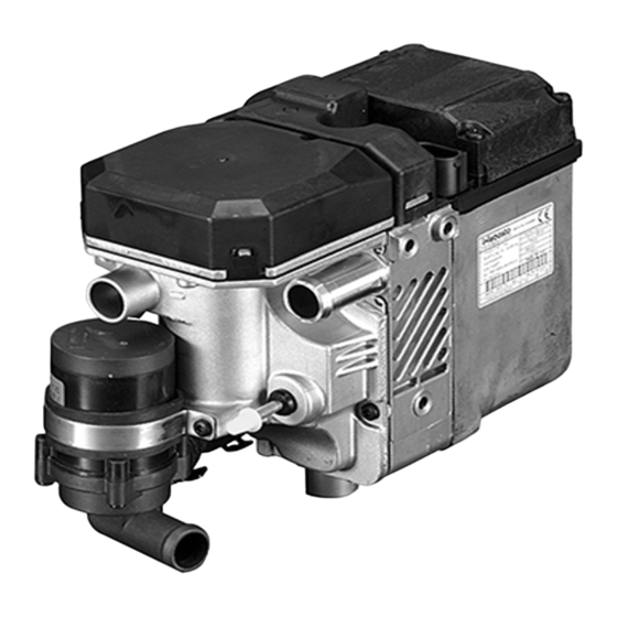
Water Heater
Thermo Top Parking Heater E
Thermo Top Parking Heater C
Thermo Top Parking Heater P
Installation Instructions
VW Polo
Diesel
from Model Year 2006
For left-hand drive vehicles only
WARNING!
Hazard warning:
Incorrect installation or repair of Webasto heating systems may cause a fire or result in the
emission of carbon monoxide, which can be fatal. Serious or fatal injuries can be caused as
a result.
Specialist company training, technical documentation, specialised tools and equipment are
required to install and repair Webasto heating and cooling systems.
Only original Webasto parts must be used. For this, also see the catalog of air and water heat-
er accessories from Webasto.
NEVER attempt to install or repair Webasto heating or cooling systems if you have not
successfully completed the company training and thereby acquired the required tech-
nical skills, or if you do not have access to the required technical documentation, tools
and equipment needed to carry out correct installation and repairs.
ALWAYS follow all Webasto installation and repair instructions and observe all warnings.
Webasto does not accept any liability for defects and damage that are attributable to installa-
tion by untrained staff.
Ident. No.: 9015699D_EN
e1
00 0003
e1
00 0002
e1
00 0104
Fee Euro 10.00
Feel the drive
© Webasto AG
Advertisement
Table of Contents

Related Manuals for Webasto Thermo Top P


Summary of Contents for Webasto Thermo Top P
-
Page 1: Installation Instructions
Specialist company training, technical documentation, specialised tools and equipment are required to install and repair Webasto heating and cooling systems. Only original Webasto parts must be used. For this, also see the catalog of air and water heat- er accessories from Webasto. -
Page 2: Table Of Contents
VW Polo Table of Contents Validity Preparing heater Heater/Installation Kit Preparing installation location Foreword Installing heater General Instructions Coolant circuit with engine code letters: AMF 17 Special Tool Coolant circuit with engine code letters: BNV and BNM 21 Explanatory Notes on Document Combustion air Preliminary Work Fuel... -
Page 3: Heater/Installation Kit
Thermo Top E Mid-size car, station wagon Thermo Top C Full-size car, van, offroader Thermo Top P The selection of the heater is based on the passenger compartment size of the vehicle and the level of comfort required by the customer! Foreword... -
Page 4: Explanatory Notes On Document
VW Polo Explanatory Notes on Document To provide you with a quick overview of the individual working steps, you will find an identification mark on the outside top right corner of the page in question. Mechanical system Electrical system Coolant circuit Fuel Exhaust gas Combustion air... -
Page 5: Preliminary Work
VW Polo Preliminary Work WARNING! - Disconnect the battery "earth" or "ground" connection. - Depressurize the cooling system. - Copy the factory number from the original type label to the duplicate type label. - Remove years that do not apply from the duplicate label. - Attach the duplicate label (type label) in the appropriate place. - Page 6 VW Polo Preparing electrical system Only with Climatronic gn/ws rt/ws Produce connections as shown in wiring dia- gram. Fasten wire section 1 with insulating gn/ws tape on the fan wiring harness. Preparing exhaust pipe Connect the included lines to IPCU. Crimp 8mm dia.
-
Page 7: Electrical System
VW Polo Electrical system Wiring harness pass through Digital timer 1 Protective rubber plug of Bowden cable 1 Digital timer Wiring har- Do not install the metering pump ness in- cable harness until later together stallation with fuel pipe along the original diagram vehicle fuel lines on the under- body... -
Page 8: Climatic Fan Controller
Webasto VW Polo rt/sw SB36 T10c/1 sw/rt sw/rt gn/ws Climatic wiring dia- gram Webasto components Components of VW Polo Colours and symbols Heater Fan motor - V2 6-pin heater connector SB36 25 A fuse white 25 A fuse Resistor group... -
Page 9: Climatronic Fan Controller
Climatron- ic wiring diagram T6ac J127 sw/ws IPCU T12g gn/ws J255 Webasto components Components of VW Polo Colours and symbols Heater J127 Fan unit 6-pin heater connector J255 A/C control panel white 25 A fuse SB36 25 A fuse... - Page 10 VW Polo Insert IPCU base in free socket. Produce connections as shown in wiring dia- gram. 1 IPCU Connec- tion to re- lay carrier Connection on connector T12g 3 , Pin 3 of A/C control panel 4 . Produce connections as shown in wiring dia- gram.
-
Page 11: Remote Option (Telestart)
VW Polo Remote option (Telestart) 1 Receiver 2 4 mm dia. hole [2x], 4.8x13 self-tapping screw [2x] 3 Bracket Installing receiver 1 Antenna Installing antenna Temperature sensor for HTM100 only 1 Cable tie 2 Temperature sensor Installing tempera- ture sensor... -
Page 12: Remote Option (Thermo Call)
VW Polo Remote option (Thermo Call) Mount TC receiver on A-pillar as shown; mounting materials not included in delivery scope! 1 Receiver 2 M5x16 bolt, large diameter washer, M5 Installing flanged nut receiver Copy hole pattern 2 of TC receiver 1 to right- hand A-pillar as shown. -
Page 13: Preparing Heater
VW Polo Preparing heater Only on vehicles with engine code letters: AMF! Discard section X Cut heat protection hose in half, compress Cutting and push onto hose B and E . coolant hose to b = 1050mm length c = 210mm e = 730mm 40mm Discard section X... - Page 14 VW Polo Hose D with engine code letters: AMF! Hose C with engine code letters: BNV and BNM! 1 27 mm dia. spring clip from water pump 2 20x20 connecting pipe 3 27 mm dia. spring clip from water pump Installing coolant hose on...
-
Page 15: Preparing Installation Location
VW Polo Preparing installation location Discard original vehicle bolts from engine mount and replace with included double bolts. Observe tightening torque according to manufacturer. Preparing 1 Double bolt [2x] installa- tion loca- tion 1 Right-hand frame side member. 2 M8 rivet nut Installing rivet nut 1 Loosely mount bracket... -
Page 16: Installing Heater
VW Polo Installing heater Before installing heater, tighten fastening bolts of bracket. Tighten Ejot screws to 10 Nm! Insert two 6 mm dia. washers between heater and bracket at position 2 . 1 Ejot screw Installing 2 Ejot screw, washer [2x] heater Tighten strut on heater following installation. -
Page 17: Coolant Circuit With Engine Code Letters: Amf
VW Polo Coolant circuit with engine code letters: AMF WARNING! Any coolant running off should be collected using an appropriate container. Install hoses so that they are kink-free! Unless specified otherwise, always fasten using cable ties. Position clamps so that no other hose can be damaged! When installing the hoses, the heater must be filled with coolant! The connection should be "inline"... - Page 18 VW Polo 1 Original vehicle bolt 2 Angle bracket with long leg under bolt 3 M6x16 bolt, M6 flanged nut 4 Circulating pump 5 Rubber-coated pipe clamp, 48 mm dia. Fastening circulating pump 1 Circulating pump Connec- tion to heater and circulating pump Before producing electrical connection, cut...
- Page 19 VW Polo Install hose B with 90° elbow on circulating pump 1 . Connec- tion to cir- culating pump 1 Spacer bracket Routing in engine compart- ment 1 Spacer bracket [2x] Routing in engine compart- ment Install individual spacer bracket 3 with brack- et for air intake silencer 1 .
- Page 20 VW Polo 1 Charge-air tube 2 Premounted spacer bracket Routing in engine compart- ment Remove and dispose of original vehicle cool- ant hose 1 . The spring clips will be reused. Removing coolant hose 1 Heat exchanger inlet 2 Heat protection hose Connec- tion to heat exchanger...
-
Page 21: Coolant Circuit With Engine Code Letters: Bnv And Bnm
VW Polo Coolant circuit with engine code letters: BNV and BNM WARNING! Any coolant running off should be collected using an appropriate container. Install hoses so that they are kink-free! Unless specified otherwise, always fasten using cable ties. Position clamps so that no other hose can be damaged! When installing the hoses, the heater must be filled with coolant! The connection should be "inline"... - Page 22 VW Polo 1 Original vehicle bolt 2 Angle bracket with long leg under bolt 3 M6x16 bolt, M6 flanged nut 4 Circulating pump 5 Rubber-coated pipe clamp, 48 mm dia. Fastening circulating pump 1 Circulating pump Connec- tion to heater and circulating pump Before producing electrical connection, cut...
- Page 23 VW Polo Install hose A with 90° elbow on circulating pump 1 . Connec- tion to cir- culating pump 1 Spacer bracket Routing in engine compart- ment 1 Spacer bracket [2x] Routing in engine compart- ment Install individual spacer bracket 3 with brack- et for air intake silencer 1 .
- Page 24 VW Polo 1 Charge-air intake pipe 2 Premounted spacer bracket Routing in engine compart- ment Pull original vehicle coolant hose 1 off con- nection piece and turn toward right-hand side of vehicle. Spring clip 2 will be reused. Preparing coolant Before installing, push black (sw) rubber iso- lator 2 onto original vehicle coolant hose 1 .
- Page 25 VW Polo 1 Spacer bracket Installing spacer bracket...
-
Page 26: Combustion Air
VW Polo Combustion air 1 Flexible tube 2 20-27 mm dia. hose clamp Installing intake pipe 1 Combustion-air intake pipe 2 Intake silencer 3 48 mm dia. clamp, flanged nut on pre- mounted M6x16 bolt Installing silencer... -
Page 27: Fuel
VW Polo Fuel CAUTION! Open the vehicle's fuel tank cap, ventilate the tank and then re-close the tank lock. Catch any fuel running off with an appropriate container. Install fuel line and metering-pump wiring harness so that they are protected against stone impact. Un- less specified otherwise, always fasten using cable ties. - Page 28 VW Polo Remove stoneguard in area of hole. 1 Silent block, M6 flanged nut in existing hole Installing metering pump 1 Metering pump 2 Rubber-coated p-clamp, M6 flanged nut on silent block 3 Hose section 4 Hose section from heater, 10 mm dia. hose clamp [2x] Installing metering...
- Page 29 VW Polo Install fuel-tank sending unit according to manufacturer's specifications. Shorten moulded hose by 10 mm on 3.5 mm dia. side and mount on fuel standpipe. 1 Moulded hose, 3.5 mm dia. 4.5 mm 2 Fuel line Connect- 3 10mm dia. Caillau clamp ing fuel 4 8mm dia.
-
Page 30: Exhaust Gas
VW Polo Exhaust gas Exhaust pipe a = 380 mm Exhaust end section b = 320 mm Preparing exhaust Discard section pipe 1 Perforated bracket Angling down per- forated bracket 90° 1 Original vehicle nut 2 Angled-down perforated bracket 3 M6x12 bolt, flanged nut M6 4 Exhaust silencer 5 Exhaust pipe... -
Page 31: Final Work
2 42 mm dia. hole, red rubber isolator with groove Cutting out wheel well trim Feel the drive Webasto AG Postfach 80 D-82132 Stockdorf / Germany National Hotline: 01805 93 22 78 (14 Cent aus dem deutschen Festnetz) Hotfax: 0395 5592 353 Hotmail: hotline@webasto.de... -
Page 32: Template For Fuel Standpipe And Fuel-Tank Sending Unit
VW Polo Template for Fuel Standpipe and Fuel-Tank Sending Unit Description Fuel hose 90° moulded hose Standpipe Fuel standpipe Single-lug clamp, 8.0mm dia. Single-lug clamp, 6.6mm dia. Caillau clamp, 9.0mm dia. Caillau clamp, 10.0mm dia. Fuel line Cut to length slantwise... -
Page 33: Operating Instructions For End Customer
VW Polo Operating Instructions for End Customer Please remove page and add to the vehicle operating instructions. Note: We recommend matching the heating time to the driving time. Heating time = driving time Example: For a driving time of approx. 20 min. (in one direction), we recommend not exceeding a switch-on time of 20 min.
Need help?
Do you have a question about the Thermo Top P and is the answer not in the manual?
Questions and answers