Webasto Thermo Top E Installation Instructions Manual
For volkswagen 2006 fox
Hide thumbs
Also See for Thermo Top E:
- Installation documentation (41 pages) ,
- Installation instructions manual (36 pages) ,
- Manual (31 pages)
Table of Contents
Advertisement
Quick Links
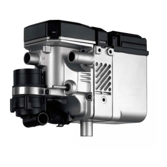
Water Heater Unit
Thermo Top E Auxiliary Heating
Thermo Top C Auxiliary Heating
Thermo Top P Auxiliary Heating
Installation Instructions
VW Fox
Gasoline
From model year 2006
For left-hand drive vehicles only
WARNING!
Hazard warning:
Incorrect installation or repair of Webasto heating systems may cause a fire or result
in the emission of carbon monoxide, which can be fatal. Serious or fatal injuries can
be caused as a result.
Specialist company training, technical documentation, specialized tools and
equipment are required to install and repair Webasto heating and cooling systems.
NEVER attempt to install or repair Webasto heating or cooling systems if you have not
successfully completed the company training and thereby acquired the required
technical skills or if you do not have access to the required technical documentation,
tools and equipment to carry out correct installation and repairs.
ALWAYS follow all Webasto installation and repair instructions and observe all
warning instructions.
Webasto does not accept any liability for defects and damage that are attributable to
installation by untrained staff.
Ident. No.: 9015968A
e1
00 0003
e1
00 0002
e1
00 0104
€10 fee
Feel the drive
© Webasto AG
Advertisement
Table of Contents

Related Manuals for Webasto Thermo Top E


Summary of Contents for Webasto Thermo Top E
-
Page 1: Installation Instructions
Specialist company training, technical documentation, specialized tools and equipment are required to install and repair Webasto heating and cooling systems. NEVER attempt to install or repair Webasto heating or cooling systems if you have not successfully completed the company training and thereby acquired the required technical skills or if you do not have access to the required technical documentation, tools and equipment to carry out correct installation and repairs. -
Page 2: Table Of Contents
VW Fox Table of Contents Validity Preparing the Heater Unit Heater Unit / Installation Kit Preparing the Installation Location Foreword Installing the Heater Unit General Instructions Combustion Air Special Tools Exhaust System Explanatory Notes on the Document Water Connection Preliminary Work Fuel Connection Heater Unit Installation Location Final Work... -
Page 3: Heater Unit / Installation Kit
9015515B Recommended heater unit for the relevant vehicle class: Vehicle Heater unit Compact car Thermo Top E Mid-class, station wagon Thermo Top C Luxury, van, off-roader Thermo Top P Select the heater unit based on the size of the vehicle passenger compartment and the customer's comfort requirements. -
Page 4: Explanatory Notes On The Document
Specific risk of damage to components. Specific risk of fire or explosion. Reference to general installation instructions of Webasto components or to the manufacturer's vehicle- specific documents. Reference to a special technical feature. The arrow in the vehicle icon indicates the position on the vehicle and the angle. -
Page 5: Preliminary Work
VW Fox Preliminary Work WARNING! - Disconnect the battery. - Let off pressure in the cooling system. - Copy the factory number from the original type label to the duplicate type label. - Remove years that do not apply from the duplicate label. - Attach the duplicate label (type label) in the appropriate place. -
Page 6: Electrical Connections
VW Fox Electrical Connections Cable harness feed-through Time switch 1 Bowden cable rubber sleeve 1 Time switch Cable Wait to install the metering pump harness cable harness until later, installation together with fuel pipe along the diagram original vehicle fuel lines on the underbody. -
Page 7: Climatic Blower Control
Climatic mit Climatic sw/ge SB42 T10c/1 sw/rt rt/sw Manual air gn/ws conditio- ning circuit diagram Webasto components Components VW Fox Colors and symbols Heater unit TT-C/E/P Blower motor 6-pin connector SB42 Fuse, 25A white Fuse, 25A Resistor group black Blower relay... -
Page 8: Remote Start Option
VW Fox Remote Start Option Drill bracket at position 1 to Ø 6.5 mm. 2 Receiver 1 M6x20 bolt, bracket on existing threaded bore hole Assem- bling the receiver 1 Antenna Assem- bling the antenna Temperature sensor for HTM100 only Fasten temperature sensor 1 correctly as shown in the figure. -
Page 9: Thermo Call Option
VW Fox Thermo Call Option Fasten the TC receiver 1 on the A-pillar as shown in the image, the fastening material is not a component of delivery. Assem- bling the receiver 1 Antenna Assem- bling the antenna Tip switch Assem- bling the tip switch... -
Page 10: Preparing The Heater Unit
VW Fox Preparing the Heater Unit 1 Exhaust pipe a = 370mm 2 Exhaust end section b = 110mm Preparing Dispose of section X exhaust pipe Ejot screw bolts tightening torque 10 Nm! 1 Ejot screw bolts [3x] 3 Combustion air intake pipe 4 Intake silencer 2 Ø... -
Page 11: Preparing The Installation Location
VW Fox Preparing the Installation Location Remove original vehicle bolt 1 , this will be used again. Preparing Installation Location Drill a Ø 6mm bore hole 1 according to the figure for the air intake silencer bracket. Check first for any wires! 20mm 65mm Preparing... - Page 12 VW Fox 1 Edge protection 200 mm long 2 Edge protection 100mm long Inserting edge protection...
-
Page 13: Combustion Air
VW Fox Combustion Air Insert retaining clip 1 in the Ø 6mm bore hole according to the figure. Inserting retaining clip Fasten the combustion air intake silencer 1 to the hole in the strut 3 with cable ties 2 . Assem- bling the vacuum... -
Page 14: Exhaust System
VW Fox Exhaust System Ensure sufficient distance from adjacent components. 1 Pre-assembled exhaust pipe 2 Tighten the hose clamp Assem- 3 Bracket, M6 bolt on pre-assembled Ejot bling the stay bolt exhaust 4 Exhaust silencer pipe Ensure sufficient distance from adjacent components. -
Page 15: Water Connection
VW Fox Water Connection WARNING! Tighten all hose clamps with 2.0 + 0.5 Nm. Any coolant running off should be collected using an appropriate container. Install hoses so that they are kink-free. Unless specified otherwise, always fasten using cable clips. Position hose clamps and spring band clamps so that no other hose can be damaged. - Page 16 VW Fox a = 1,010mm b = 820mm Dispose of section X Cutting water hose into sections Prepare the water hoses according to the illustration 1 Black (sw) rubber profile [2x] 2 Hose bracket Preparing the water hoses Assemble the bracket 1 and 2 according to the illustration.
- Page 17 VW Fox Connec- ting to the heater unit 1 Cable clip 2 Position the black (sw) rubber profile Placement in the engine compart- ment Align the pre-assembled bracket 1 according to the illustration. Note the manufactures recommendations for the torque to screw on the on the engine bearing bracket.
- Page 18 VW Fox Insert the hose bracket 1 as shown in the figure. 2 Engine exhaust hose section Connec- ting to the engine outlet Before connecting, fill the water hoses with coolant. Align the black (sw) rubber profile 1 according to the illustration. 2 Heat exchanger inlet hose section Connec- 3 Cable clips...
-
Page 19: Fuel Connection
VW Fox Fuel Connection CAUTION! Open the vehicle's tank-cap lock, ventilate the tank and then re-close the tank lock. Catch any fuel running off with an appropriate container. Install fuel line and metering pump cable harness so that they are protected against stone impact. Unless specified otherwise, always fasten using cable clips. - Page 20 VW Fox Remove the tank mounting 1 according to the manufacturer's instructions. 1 Tank mounting 2 Body washer Ø 6 mm 3 Copy the hole image, Ø 6mm bore hole Fuel take- Cut the tank extracting device 1 into sections and insert according to the template, see the Installation Instructions.
-
Page 21: Final Work
- Attach the "Switch off auxiliary heating before re-fuelling" sticker onto the left side of the B-pillar. Feel the drive Webasto AG Postfach 80 - 82132 Stockdorf - Hotline 0 18 05 / 93 22 78 Hotfax (0395) 55 92-353 - http://www.webasto.de Printed in Germany 06/06Printed by: Steffen... -
Page 22: Operating Instructions For The End Customer
VW Fox Operating instructions for the end customer Please remove page and add to the vehicle operating instructions. Before parking the vehicle, make the following settings: 1 Temperature to "max." 2 Air outlet to “windscreen” 3 Blower set to level "1" or "2" vehicles with and without... -
Page 23: Tank Extracting Device Template
VW Fox Tank Extracting Device Template 100 mm Scale 1:1 Compare the size of the printed version with dimension lines. Permitted tolerance a maximum of 2%. Set the printer settings to “no margin” or “minimize margins” and 100% of the normal size. 100 mm...
Need help?
Do you have a question about the Thermo Top E and is the answer not in the manual?
Questions and answers