Webasto Thermo Top E Installation Instructions Manual
Fiat 2007 bravo
Hide thumbs
Also See for Thermo Top E:
- Installation documentation (41 pages) ,
- Installation instructions manual (36 pages) ,
- Manual (31 pages)
Table of Contents
Advertisement
Quick Links
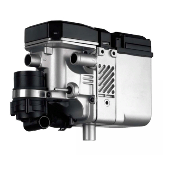
Water Heater Unit
Thermo Top E Additional Heater
Thermo Top C Additional Heater
Thermo Top P Additional Heater
Installation Instructions
Fiat Bravo
Gasoline and Diesel
from Model Year 2007
Left-hand drive vehicle
WARNING!
Hazard warning:
Incorrect installation or repair of Webasto heating systems may cause a fire or result in the
emission of carbon monoxide, which can be fatal. Serious or fatal injuries can be caused as
a result.
Specialist company training, technical documentation, specialized tools and equipment are
required to install and repair Webasto heating and cooling systems.
NEVER attempt to install or repair Webasto heating or cooling systems if you have not
successfully completed the company training and thereby acquired the required technical
skills, or if you do not have access to the required technical documentation, tools and
equipment needed to carry out correct installation and repairs.
ALWAYS follow all Webasto installation and repair instructions and observe all warnings.
Webasto does not accept any liability for defects and damage that are attributable to
installation by untrained staff.
Ident. No.:1312960A_EN
e1
00 0003
e1
00 0002
e1
00 0104
Fee Euro 10.00
Feel the drive
© Webasto AG
Advertisement
Table of Contents

Related Manuals for Webasto Thermo Top E


Summary of Contents for Webasto Thermo Top E
-
Page 1: Installation Instructions
Left-hand drive vehicle WARNING! Hazard warning: Incorrect installation or repair of Webasto heating systems may cause a fire or result in the emission of carbon monoxide, which can be fatal. Serious or fatal injuries can be caused as a result. -
Page 2: Table Of Contents
Fiat Bravo Table of Contents Heater Unit/Installation Kit Water Foreword All vehicles General Instructions Gasoline Special Tools Diesel Explanatory Notes on Document Fuel Preliminary Work Combustion air Heater unit installation location Exhaust gas Preparing electrical system Final Work Electrical system Operating Instructions for End Customer Fan controller for manual air conditioning Automatic air-conditioning fan controller... -
Page 3: Heater Unit/Installation Kit
1312956A Heater unit recommended for the respective vehicle class: Vehicle Heater unit Compact car Thermo Top E Mid-size car, station wagon Thermo Top C Full-size car, van, offroader Thermo Top P The selection of the heater unit is based on the passenger compartment size of the vehicle and the... -
Page 4: Explanatory Notes On Document
Specific risk of damage to components. Specific risk of fire or explosion. Reference to general installation instructions of Webasto components or to the manufacturer's vehicle- specific documents. Reference to a special technical feature. The arrow in the vehicle icon indicates the position on the vehicle and the angle. -
Page 5: Preliminary Work
Fiat Bravo Preliminary Work WARNING! - Open fuel tank cap, ventilate tank. - Close the tank cap again. - Disconnect the battery "earth" or "ground" connection. - Depressurize the cooling system. - Copy the factory number from the original type label to the duplicate type label. - Remove years that do not apply from the duplicate label. -
Page 6: Preparing Electrical System
Fiat Bravo Preparing electrical system Only with automatic air-conditioning Cutting wires to length O,75² 1750 Produce connections as shown in wiring diagram. Install wire section 2 in the protective sleeving provided. Preparing fuse F4 1312960A_EN... -
Page 7: Electrical System
Fiat Bravo Electrical system Fuse holder, relay K3 Summer/winter switch option 1 Fuse holder 1 Summer/winter switch, drilled hole 12 mm dia. 2 Angle bracket, drilled out to 8 mm dia. 3 Original vehicle stud bolt, flanged nut 4 Relay K3, M5x16 bolt, washer, flanged nut Do not install the metering pump Wiring cable harness until later together... -
Page 8: Fan Controller For Manual Air Conditioning
Webasto Fiat Wiring diagram B001B gr/ws 4² N085 gr/ws 4² D008A H081 O030 Webasto components Vehicle components Colors and symbols Heater unit TT-E/C/P N085 Fan motor 6-pin heater unit connector GRs Fan relay T8 ws white Fuse H081 Fan switch... -
Page 9: Automatic Air-Conditioning Fan Controller
D008 St A N085 ge/rt sw 0,75² ge/rt St C St A M070 St C Webasto components Vehicle components Colors and symbols HG Heater unit TT-E/C/P N085 Fan unit 6-pin heater unit connector GRs Fan relay T8 white Fuse M070... - Page 10 Fiat Bravo Connection on gray (gr) 3-pin connector B001B 1 of central electrical box. Produce connections as shown in wiring diagram. 2 Red (rt) wire from K3/87a Connect- 3 Gray/white (gr/ws) wire of fan motor ing fan-mo- 4 Black (sw) wire from K3/30 5 Gray/white (gr/ws) wire of connector Connection on 12-pin connector 2 from A/C control panel 3 .
-
Page 11: Remote Option (Telestart)
Fiat Bravo Remote option (Telestart) 1 Receiver 2 Original vehicle stud bolt, original vehicle flanged nut 3 Bracket, hole drilled out to 6.5 mm dia. Installing receiver 1 Antenna Installing antenna 1312960A_EN... -
Page 12: Preparing Heater Unit
Fiat Bravo Preparing heater unit Washer on Ejot stud 2 ! 1 Heater unit Premount- ing heater unit Preparing installation location Mount bracket 2 on original vehicle stud bolt 3 with flanged nut, align and copy hole pattern. Copying 1 Hole pattern, 9.1 mm dia. hole hole 4 Hole pattern, 6.5 mm dia. - Page 13 Fiat Bravo 1 100 mm edge protection section Mounting edge protection section 1 50 mm edge protection section Mounting edge protection section 1 50 mm edge protection section Mounting edge protection section 1312960A_EN...
-
Page 14: Installing Bracket
Fiat Bravo Installing bracket 1 M6x30 bolt, spring washer, 8 mm shim, M6 rivet nut 2 Original vehicle stud bolt, 5 mm shim, flanged nut Installing 3 M6x50 bolt [2x], 30 mm spacer [2x], 8 mm bracket shim [2x], flanged nut [2x] 4 Bracket Installing heater unit Connect wiring harness of heater unit before... -
Page 15: Water
Fiat Bravo Water WARNING! Any coolant running off should be collected using an appropriate container. Install hoses so that they are kink-free. Unless specified otherwise, always fasten using cable ties. Position clamps so that no other hose can be damaged! When installing the coolant hose, the heater unit must be filled with coolant. -
Page 16: All Vehicles
Fiat Bravo Gasoline c = 1280 Diesel Cutting hose C to c = 1220 length Discard section X All vehicles Slide braided protection hose onto hose C and cut to length. Cut heat shrink plastic tubing to length. Braided 1 25 mm long heat shrink plastic tubing [2x] protection hose C a = 970... - Page 17 Fiat Bravo Bend 48 mm dia. rubber-coated p-clamp 1 . Preparing p-clamp Bend perforated bracket 1 by 90°. Preparing perforated bracket 1 Perforated bracket, angled down 2 M6x20 bolt, flanged nut 3 48 mm dia. rubber-coated p-clamp Premount- ing p- clamp 1 Perforated bracket 2 M6x20 bolt, original vehicle hole, flanged...
-
Page 18: Gasoline
Fiat Bravo Connec- tion to heater unit Gasoline 1 Engine-outlet hose section 2 Hose section of heat exchanger inlet Cutting point 1 48 mm dia. rubber-coated p-clamp Routing in engine compart- ment Routing in engine compart- ment 1312960A_EN... - Page 19 Fiat Bravo Ensure sufficient distance to neighboring components. 1 Hose on heat exchanger inlet Connect- ing heat exchanger inlet 1 Hose on engine outlet 2 Spacer bracket Connect- ing engine outlet 1 48 mm dia. rubber-coated p-clamp Routing in engine compart- ment 1 Cable tie...
-
Page 20: Diesel
Fiat Bravo 1 Cable tie [5x] Routing in engine compart- ment Diesel 1 Engine-outlet hose section 2 Hose section of heat exchanger inlet 3 Cutting point Cutting point 1 48 mm dia. rubber-coated p-clamp Routing in engine compart- ment 2 Hose section of heat exchanger inlet Connect- ing heat exchanger... - Page 21 Fiat Bravo 1 Engine-outlet hose section 2 Spacer bracket Connect- ing engine outlet 1 48 mm dia. rubber-coated p-clamp Routing in engine compart- ment Connect- ing hose A and B 1312960A_EN...
-
Page 22: Fuel
Fiat Bravo Fuel CAUTION! Open the vehicle's fuel tank lock, ventilate the fuel tank and then re-close the tank lock. Catch any fuel running off with an appropriate container. Install fuel line and metering-pump wiring harness so that they are protected against stone impact. Unless specified otherwise, always fasten using cable ties. - Page 23 Fiat Bravo Cut fuel standpipe 1 to length. Cutting fuel standpipe to length Shape fuel standpipe 1 . Shape fuel standpipe 1 Cutting point 2 Fuel-tank vent line Removing fuel Mount fuel standpipe 3 in fuel- tank vent line 1 . Align removal pipe of fuel standpipe to fuel tank bottom.
- Page 24 Fiat Bravo Align fuel standpipe 1 so that freedom of movement of fuel gauge is ensured after mounting fuel-tank sending unit. 2 Opening of fuel-tank sending unit Removing fuel 1 Fuel standpipe 2 8 mm dia. clamp 3 Hose section, 9 mm dia. clamp 4 Fuel line Connect- ing fuel...
-
Page 25: Combustion Air
Fiat Bravo Combustion air 1 Combustion air pipe a = 210 Discard section X Cutting combus- tion air pipe to length 1 Combustion-air intake pipe 2 27 mm dia. clamp Installing intake pipe 1 Intake muffler 2 Cable tie, original vehicle hole 3 Combustion-air intake pipe Installing muffler... -
Page 26: Exhaust Gas
Fiat Bravo Exhaust gas 1 Exhaust pipe a = 170 2 Exhaust end section b = 230 Preparing exhaust Discard section X pipe Bend perforated bracket 1 by 90°. Preparing perforated bracket All following photos show diesel vehicle. 1 M6x30 spacer nut, Ejot stud 2 Exhaust muffler 3 M6x12 bolt, spring lockwasher Installing... - Page 27 Fiat Bravo 1 Hose clamp [2x] 2 Exhaust pipe Installing exhaust pipe Secure wiring harness of pressure switch 3 in bracket of A/C line. Ensure sufficient spacing between exhaust end section 2 and charge-air tube 3 . 1 Hose clamp Installing 5 Perforated bracket exhaust...
-
Page 28: Final Work
- Check the proper operation of the additional heater, see the operating instructions/installation instructions. - Attach the "Switch off additional heater before refueling" sticker to the left-hand B-pillar. Feel the drive Webasto AG Postfach 80 - 82132 Stockdorf Hotline 01805 / 932278 - Hotfax 0395 / 5592-353 http://www.webasto.de... -
Page 29: Operating Instructions For End Customer
Fiat Bravo Operating Instructions for End Customer Please remove page and add to the vehicle operating instructions. Note: We recommend matching the heating time to the driving time. Heating time = driving time Example: For a driving time of approx. 20 min. (in one direction), we recommend not exceeding a switch-on time of 20 min.
Need help?
Do you have a question about the Thermo Top E and is the answer not in the manual?
Questions and answers