Webasto Thermo Top E Installation Instructions Manual
For honda 2006 civic
Hide thumbs
Also See for Thermo Top E:
- Installation documentation (41 pages) ,
- Installation instructions manual (36 pages) ,
- Manual (31 pages)
Table of Contents
Advertisement
Quick Links
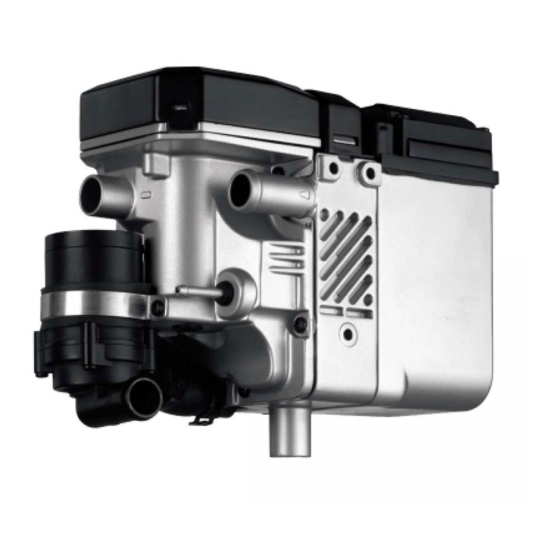
Water Heater Unit
Thermo Top E Additional Heater
Thermo Top C Additional Heater
Thermo Top P Additional Heater
Installation Instructions
Honda Civic
Gasoline
from Model Year 2006
For left-hand drive vehicles only
WARNING!
Hazard warning:
Incorrect installation or repair of Webasto heating systems may cause a fire or result
in the emission of carbon monoxide, which can be fatal. Serious or fatal injuries can
be caused as a result.
Specialist company training, technical documentation, specialized tools and
equipment are required to install and repair Webasto heating and cooling systems.
NEVER attempt to install or repair Webasto heating or cooling systems if you have not
successfully completed the company training and thereby acquired the required
technical skills, or if you do not have access to the required technical documentation,
tools and equipment needed to carry out correct installation and repairs.
ALWAYS follow all Webasto installation and repair instructions and observe all
warnings.
Webasto does not accept any liability for defects and damage that are attributable to
installation by untrained staff.
Ident. No.: 1311074C_EN
e1
00 0003
e1
00 0002
e1
00 0104
Fee Euro 10
Feel the drive
© Webasto AG
Advertisement
Table of Contents

Subscribe to Our Youtube Channel
Related Manuals for Webasto Thermo Top E


Summary of Contents for Webasto Thermo Top E
-
Page 1: Installation Instructions
Specialist company training, technical documentation, specialized tools and equipment are required to install and repair Webasto heating and cooling systems. NEVER attempt to install or repair Webasto heating or cooling systems if you have not successfully completed the company training and thereby acquired the required technical skills, or if you do not have access to the required technical documentation, tools and equipment needed to carry out correct installation and repairs. -
Page 2: Table Of Contents
Honda Civic Table of Contents Validity Preparing heater unit Heater Unit/Installation Kit Preparing Installation Location Foreword Installing heater unit General Instructions Coolant connection Special Tools Combustion air Explanatory Notes on Document Fuel Connection Preliminary Work Exhaust system Heater unit installation location Final Work Preparing electrical system Operating Instructions for End Customer... -
Page 3: Heater Unit/Installation Kit
1311070B Heater unit recommended for the respective vehicle class: Vehicle Heater unit Compact car Thermo Top E Mid-size car, station wagon Thermo Top C Full-size car, van, offroader Thermo Top P The selection of the heater unit is based on the passenger compartment size of the vehicle and the... -
Page 4: Explanatory Notes On Document
Specific risk of damage to components. Specific risk of fire or explosion. Reference to general installation instructions of Webasto components or to the manufacturer's vehicle- specific documents. Reference to a special technical feature. The arrow in the vehicle icon indicates the position on the vehicle and the angle. -
Page 5: Preliminary Work
Honda Civic Preliminary Work WARNING! - Disconnect the battery "earth" or "ground" connection. - Depressurize the cooling system. - Copy the factory number from the original type label to the duplicate type label. - Remove years that do not apply from the duplicate label. - Attach the duplicate label (type label) in the appropriate place. -
Page 6: Preparing Electrical System
Honda Civic Preparing electrical system Cut included black (sw) wire to a length of 3,000 mm as shown. 0,5² All wire are required for connection of IPCU and fan controller! Cutting wires to 0,5² length 0,5² Pull wire section 3 into protective sleeving provided [2x] and route into passenger compartment together with clock and fan wiring harness. -
Page 7: Electrical Connections
Honda Civic Electrical Connections Wiring harness pass through Digital timer 1 Protective rubber plug 1 Digital timer Do not install the metering pump cable harness until later together with fuel pipe along the original vehicle fuel lines on the underbody Wiring harness installation... -
Page 8: Fan Controller
Honda Civic Fan controller Connection on 2-pin connector 1 from wiring harness of fan relay to fan motor. Make connections as shown in the wiring diagram with the connectors provided. Con- 2 White (ws) wire from fan relay necting fan 3 Red (rt) wire to K3/87a motor 4 Black (sw) wire from K3/30... - Page 9 St 2 Automatic air-con- 4² ditioning circuit diagram 0,5² 0,5² IPCU 0,5² 0,5² St 1 Webasto components Components of Honda Civic Colors and symbols Heater unit TT-C/E Fan motor 6-pin connector Fan relay white Fuse Air-conditioning control black panel Fan relay...
-
Page 10: Remote Option (Telestart)
Honda Civic Remote option (Telestart) 3 Receiver 1 Original vehicle bolt 2 Telestart bracket, drill out hole to 7 mm dia. Installing receiver 1 Antenna Installing antenna Temperature sensor for HTM100 only 1 Fasten temperature sensor with installation tape 2 Original vehicle air duct Installing tempera- ture sensor... -
Page 11: Preparing Heater Unit
Honda Civic Preparing heater unit Coolant hose 1 = 20 mm dia. b = 90 mm c = 30 mm Cutting Discard section X coolant hose 1 to length 1 Heater unit 2 Hose clamp 3 18x20 connecting pipe 4 Combustion-air intake pipe Preassem- bling heater unit... -
Page 12: Installing Heater Unit
Honda Civic 1 Bracket 2 Copy hole pattern, 7 mm dia. drilled hole 3 Copy hole pattern, drill 9 mm dia. hole and mount M6 rivet nut 4 Original vehicle bolt Copying hole pattern 1 M6x20 bolt, M6 flanged nut 2 Premounted M6x20 bolt, M6 flanged nut 3 M6x12 bolt, flanged nut M6 4 Strut... -
Page 13: Coolant Connection
Honda Civic Coolant connection WARNING! Tighten all hose clamps to 2.0 + 0.5 Nm. Any coolant running off should be collected using an appropriate container! Install hoses so that they are kink-free. Unless specified otherwise, always fasten using cable ties. Position hose clamps and spring band clamps so that no other hose can be damaged. - Page 14 Honda Civic Coolant hose 2 = 18 mm dia. a = 580 mm d = 870 mm Discard section X Cutting coolant hose 2 to length Cut braided protection hose in half and push onto hose A and D . Cut heat shrink plastic tubing into 4 pieces.
- Page 15 Honda Civic Con- nection on heater unit 1 M6x20 bolt, M6 flanged nut 2 Rubber-coated pipe clamp Routing in engine compart- ment Routing in engine compart- ment Install hose D with 90° elbow on heat exchanger inlet. Con- nection on heat exchanger inlet...
- Page 16 Honda Civic Con- nection on heater unit Before connecting, fill the coolant hoses with coolant. Install hose A with 180° elbow on engine outlet 1 . Con- nection to engine outlet 1 Rubber-coated pipe clamp 2 M6x16 bolt, spring lockwasher, existing thread Routing in engine...
-
Page 17: Combustion Air
Honda Civic Combustion air 1 Combustion-air intake pipe Installing intake pipe 1 Combustion-air intake muffler 2 Cable tie 3 Combustion-air intake pipe Installing muffler... -
Page 18: Fuel Connection
Honda Civic Fuel Connection CAUTION! Open the vehicle's fuel tank cap, ventilate the tank and then re-close the tank lock. Catch any fuel running off with an appropriate container. Install fuel line and metering-pump wiring harness so that they are protected against stone impact. Unless specified otherwise, always fasten using cable ties. - Page 19 Honda Civic Remove and dismantle fuel-tank sending unit according to manufacturer's instructions. 1 Fuel-tank sending unit 2 Washer 3 Copy hole pattern, 6 mm dia. hole Removing fuel Insert fuel standpipe, see "Installation Instructions“. Install 5 washers between cover of fuel-tank sending unit and nut of fuel standpipe at position 2 1 Fuel standpipe Installing...
- Page 20 Honda Civic Install fuel-tank sending unit according to manufacturer's specifications. 1 9 mm dia. Caillau clamp 2 Molded hose, dia. 3.5 mm x 4.5 mm 3 10 mm dia. Caillau clamp 4 Remaining end of Mecanyl fuel line Con- necting fuel line Fuel line from fuel standpipe on intake side of metering pump [side without connector].
-
Page 21: Exhaust System
Honda Civic Exhaust system 1 Exhaust pipe a = 260 mm 2 Exhaust end section b = 210 mm Preparing exhaust Discard section X pipe 1 Exhaust pipe 2 Hose clamp Installing exhaust pipe 1 Muffler 2 30 mm long spacer 3 Exhaust pipe 4 Hose clamp 5 M6x50 bolt, large diameter washer, M6... -
Page 22: Final Work
2 Drill out existing hole to 42 mm dia., red (rt) rubber isolator with groove Mounting rubber isolator Feel the drive Webasto AG Postfach 80 - 82132 Stockdorf, Germany - Hotline +49- (0)1805-932278 Hotfax +49-(0)395-5592-353 - http://www.webasto.de Printed in Germany 03/07Printed by: Steffen... -
Page 23: Operating Instructions For End Customer
Honda Civic Operating Instructions for End Customer Please remove page and add to the vehicle operating instructions. Before parking the vehicle, make the following settings: 1 Air outlet to windshield 2 Set temperature to "max." Automatic air-con- ditioning...
Need help?
Do you have a question about the Thermo Top E and is the answer not in the manual?
Questions and answers