Table of Contents
Advertisement
Advertisement
Table of Contents

Related Manuals for socomec ENT-RK10


Summary of Contents for socomec ENT-RK10
- Page 1 UPS-ENTERPRISE 800-2000 VA PRODUCT MANUAL...
-
Page 3: Table Of Contents
UPS-ENTERPRISE 800-2000 VA Tower and rack version PRODUCT MANUAL CONTENTS SAFETY STANDARDS ......................4 GENERAL DESCRIPTION......................5 OPERATION........................5 2.1.1 Wiring diagram......................5 2.1.2 LED display and control panel ................... 6 UNPACKING AND INSTALLATION..................7 ENVIRONMENTAL REQUIREMENTS FOR INSTALLATION........... 7 CONNECTION TO THE MAINS POWER SUPPLY AND CONNECTING THE LOAD.. - Page 4 During the warranty period, SOCOMEC UPS may, at its discretion, decide to repair the product or replace the defective parts with new parts or with used parts that are equivalent to new parts in terms of functions and performance.
-
Page 5: Safety Standards
SAFETY STANDARDS 1 SAFETY STANDARDS This manual must be kept in the vicinity of the UPS, so that the operator may consult it at any time for clarifications on the correct use of the UPS. Read the manual carefully before connecting the unit to the general mains power supply and to the devices to be powered. -
Page 6: General Description
CERTIFICATE AND CONDITIONS OF WARRANTY 2 GENERAL DESCRIPTION UPS-ENTERPRISE: sure power supply for servers, graphics stations and network devices. The main purpose of the UPS is to protect sensitive and critical equipment items from the electrical disturbances that can compromise operation. Black-outs, brown-outs, variations of voltage and frequency, lightning, electrostatic discharges and rapid overvoltages are phenomena found in all office and industrial environments and which cause hardware damage and data losses. -
Page 7: Led Display And Control Panel
GENERAL DESCRIPTION 2.1.2 LED display and control panel LED 1 LED 5 LED 2 LED 6 LED 3 LED 7 LED 4 <35% <35% 35-55% 35-55% 55-75% 55-75% 75-95% 75-95% 95-100% 95-105% >105% On button (mute buzzer, reset alarms) Off button (inverter OFF) LED 1 Battery capacity % LED bar LED 2... -
Page 8: Unpacking And Installation
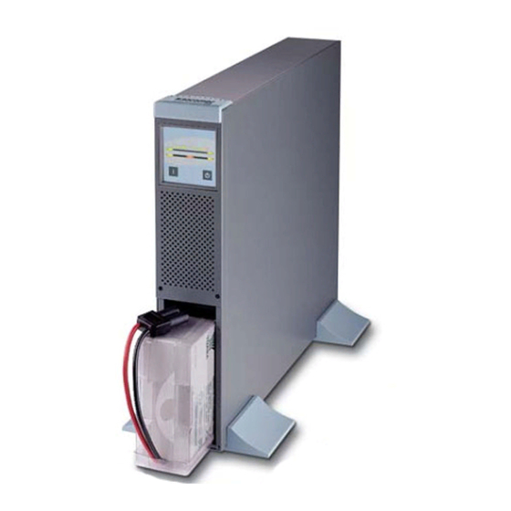
In case of RK models for installation in 19” standardized cabinets, the lateral brackets supplied must be mounted. The pictures that follow illustrate the assembly depending on the configuration. ENT-RK10 ENT-RK15 / RK20 WARNING Extract the UPS or the battery module and remove all the parts from the pack. It is strongly recommended to keep the packaging materials, which have been designed for safe shipping in cases where the unit has to be shipped back for maintenance. -
Page 9: Connection To The Mains Power Supply And Connecting The Load
UNPACKING AND INSTALLATION 3.2 CONNECTION TO THE MAINS POWER SUPPLY AND CONNECTING THE LOAD 3.2.1 Settings for connections Connection to the mains (1) and the connection of applications (2) should be made by using cables of appropriate cross-section and which conform to the standards in force. A distribution panel must be set up (if there is not one already) which can be used to isolate the mains upstream of the UPS. -
Page 10: Use Of The Battery Expansions (Optional)
CERTIFICATE AND CONDITIONS OF WARRANTY 3.2.2 Use of the battery expansions (optional) Where long-life battery operation is required, back-up expansion units are available. By combining the UPS with a battery expansion unit, back-up times of up to 60 minutes may be obtained. 3.2.3 Putting an external battery expansion into operation The table above indicates sizing of the back-up expansion depending on the consumers connected: a maximum... -
Page 11: Configuration And Start-Up
CONFIGURATION AND START UP CONFIGURATION AND START-UP 4.1 CONFIGURATION OF THE OUTPUT VOLTAGE/BATTERY EXPANSIONS WARNING The factory configuration is for operation with output voltage of 230V, without additional battery expansions. For normal uses with standard back-up, no configuration work is required. To enter configuration mode, put the “UPS in bypass”... -
Page 12: Displays & Control
CERTIFICATE AND CONDITIONS OF WARRANTY DISPLAYS & CONTROL LED lit LED off LED flashing Buzzer 5.1 COMMANDS AND SIGNALS 5.1.1 Switching on with mains power present See note After the mains power supply has been connected, the internal battery-charger is activated automatically and the UPS goes into by-pass mode. -
Page 13: Battery-Powered Operation (In Cases Of Black-Out)
DISPLAYS & CONTROL 5.1.2 Battery-powered operation (in cases of black-out) Following a failure of the mains power supply or a condition of mains out of the accepted limits, the UPS goes immediately into battery-powered operation without disturbance of the power supply to the application. An acoustic and a visual signal show the battery operation status. -
Page 14: Operating Failures
CERTIFICATE AND CONDITIONS OF WARRANTY 5.1.3 Operating failures If for any reason the red LED comes on permanently, then there is an irregular operating condition. The UPS automatically goes into by-pass mode in order to protect the consumers connected. Turn to the troubleshooting section for the solution to the problem. WARNING Where the load demands more power than the nominal power of the UPS or if there is a peak of greater than... -
Page 15: Test Procedures
DISPLAYS & CONTROL 5.2 TEST PROCEDURES 5.2.1 Battery test The battery test can be activated manually or via the SW (as long as the conditions are right). The automatic test checks the efficiency of the batteries so that, if necessary, the user can be informed when they need to be replaced in order to guarantee sure service of the UPS. -
Page 16: Use Of Signal Relay
CERTIFICATE AND CONDITIONS OF WARRANTY 6 USE OF SIGNAL RELAY An optional card is available for insertion in the slot, which is able to handle 3 isolated contact signals with which to remote relay UPS status information. The relay contacts can be PIN LAYOUT configured NO (standard) pin 2 Mains missing... -
Page 17: Technical Data
TECHNICAL DATA TECHNICAL DATA Technical data ENT-TW08 ENT-TW10 ENT-TW15 ENT-TW20 ENT-RK10 ENT-RK15 ENT-RK20 Power 800VA / 560W 1000VA / 700W 1500VA /1050W 2000VA /1400W Technology VFI (Voltage and Frequency Independent) On line double conversion Input Input voltage 160 ÷ 276Vac (1ph) -
Page 18: Maintenance
CERTIFICATE AND CONDITIONS OF WARRANTY MAINTENANCE DANGEROUS electrical voltages are generated inside the UPS. All maintenance operations to be performed SOLELY AND EXCLUSIVELY by authorized personnel. • Optimal operation of the unit is obtained by keeping it constantly powered (24 hours a day). This guarantees correct maintenance of the battery charge. - Page 19 800 VA / 1000 VA tower front view rear view Battery extension tower 1000 VA rack 19” Battery extension rack 19” Rear view Front / Rear view VIEW SECTION...
- Page 20 1500-2000 VA tower Battery extension tower rear view rear view 1500-2000 VA rack 19” Rear view Battery extension rack 19” Rear view VIEW SECTION...
- Page 21 1 Fan 1 Ventilateur 2 Slot for optional communication boards 2 Cache pour cartes de communication optionnelles 3 Output socket power share 3 Prise de sortie power share 4 RS232/USB serial port DB9 4 Connecteur série RS232/USB DB9 5 Battery connection for extension 5 Connecteur batterie pour extension externe 6 Output socket 6 Prise de sortie vers l'utilisation...
Need help?
Do you have a question about the ENT-RK10 and is the answer not in the manual?
Questions and answers