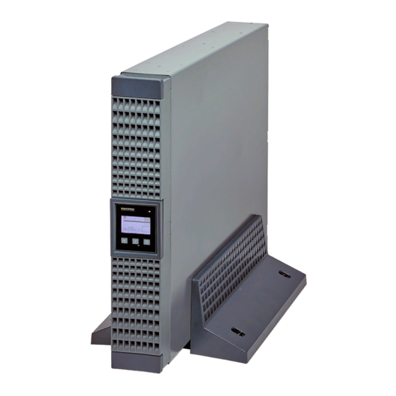
socomec NETYS RT Installation And Operating Manual
5-7-9-11 kva
Hide thumbs
Also See for NETYS RT:
- Installation and operating manual (80 pages) ,
- Options manual (9 pages) ,
- Installation and operating manual (44 pages)
Table of Contents
Advertisement
Advertisement
Table of Contents

Subscribe to Our Youtube Channel
Related Manuals for socomec NETYS RT


Summary of Contents for socomec NETYS RT
- Page 1 5- 7- 9- 11 kVA Installation and operating manual...
- Page 2 The warranty is offered on carry-in terms: components and labour for repairs supplied free of charge, and in the case of a replace- ment, the product to be returned to SOCOMEC UPS or to authorized service centres, at the customer’s own risk and expense.
-
Page 3: Table Of Contents
TABLE OF CONTENTS 1. SAFETY STANDARDS............4 1.1 Important . -
Page 4: Safety Standards
Read the manual carefully before connecting the unit to the a.c. mains supply and to the downstream appliances. Before the UPS NETYS RT is put into commission, the user must be perfectly familiar with its operation, with the position of all the controls and with the technical and functional characteristics of the unit, so as to ensure there will be no risk to any persons or to the appliance itself. -
Page 5: Description Of The Symbols Used On The Labels Applied To The Unit
2. SAFETY ISOLATE THE UPS BEFORE WORKING ON THIS CIRCUIT. External power distribution unit UPS. Legend. B Contactor solenoid. Q Mains input thermal-magnetic switch T Two-pole contactor 90 A AC1; coil voltage: according to the Mains input. 1.2 Description of the symbols used on the labels applied to the unit All the precautions and the warnings on the labels and plates on the inside and outside of the equipment should be respected. -
Page 6: Installation
Consult the following check list when installing the UPS: • NETYS RT units are designed for use in enclosed environments. • Position the UPS on a flat and stable surface in a properly ventilated room, well away from heat sources and avoiding direct expo- sure to sunlight. -
Page 7: Vertical Installation
2. INSTALLATION 2.3 Vertical installation 2.3.1 UPS Installation 5-11 kVA - Ref.: IOMNETRTXX01-GB 00... - Page 8 2. INSTALLATION 2.3.2 UPS installation with multiple battery extensions 5-11 kVA - Ref.: IOMNETRTXX01-GB 00...
-
Page 9: Horizontal Installation On Rack
2. INSTALLATION 2.4 Horizontal installation on rack 2.4.1 Rotation of mimic pannel 5-11 kVA - Ref.: IOMNETRTXX01-GB 00... - Page 10 2. INSTALLATION 2.4.2 Fitting rack brackets 5-11 kVA - Ref.: IOMNETRTXX01-GB 00...
- Page 11 2. INSTALLATION 2.4.3 Rotation of battery extension panel 5-11 kVA - Ref.: IOMNETRTXX01-GB 00...
- Page 12 2. INSTALLATION 2.4.4 Fixing to rack 1. Adapt the length of the tracks to fit the rack. 2. Secure the wing nuts. 3. Fix the track to the rack. 4. Slot in the UPS and tighten the screws. MAX 100 kg MAX 100 kg MAX 100 kg MAX 100 kg...
-
Page 13: Rear View
3. REAR VIEW COM. SLOT PARALLEL RS232 PARALLEL RS232 5 kVA 9 kVA 7 kVA 11 kVA Legend A EPO (Emergency Power Off) B Fan C Battery extension socket D Output terminals E Input terminals F Input switch G RJ45 LAN ethernet connector H Parallel D connector RS232 serial connector (JBUS protocol) L Slot for optional communication cards... -
Page 14: Connections
4. CONNECTIONS Connection to the mains power supply and to the load(s) must be made using cables of suitable cross section, in accordance with current standards. If not already provided, install a PDU panel allowing isolation of the mains supply upstream of the UPS. The panel must be equipped with an automatic switch rated high enough to handle the current draw on full load, and with a residual current device. -
Page 15: Connection Of Ups
4. CONNECTION 4.2 Connection of UPS 4.2-1 4.2-2 Mains Output Ø Ø ≥ 6 5 kVA ≥ 6 ≥ 8 ≥ 8 7 kVA ≥ 10 9 kVA ≥ 10 ≥ 10 11 kVA ≥ 10 4.2-3 4.2-4 5-11 kVA - Ref.: IOMNETRTXX01-GB 00... -
Page 16: Connection Of Battery Extension
5. CONNECTION OF BATTERY EXTENSION 5.1 Safety warnings • Before connecting the battery extension, check that it is fully compatible with the model of UPS in use. • The use of battery extensions not supplied by the manufacturer is inadvisable. WARNING! There is a risk of explosion if battery modules are replaced with others of incorrect type. - Page 17 5. CONNECTION OF BATTERY EXTENSION ON-OFF ON-OFF switch switch COM. SLOT PARALLEL RS232 PARALLEL RS232 5 kVA 9 kVA 7 kVA 11 kVA Connection of multiple batteries COM. SLOT PARALLEL RS232 5-11 kVA - Ref.: IOMNETRTXX01-GB 00...
-
Page 18: Connection Of By-Pass And Single Ups
6. CONNECTION OF BY-PASS AND SINGLE UPS 6.1 Installation of BY-PASS and single UPS TO CONNECT WITH WIRES:LOOSEN SCREWS MARKED BY 200-240Vac 200-240Vac 50/60Hz 50/60Hz TO UPS PARALLEL PORT TO UPS OUTPUT TO UPS INPUT AC OUTPUT AC INPUT MINI COM. SLOT INPUT BREAKER 230Vac... -
Page 19: Connection Of By-Pass To Single Ups
6. CONNECTION OF BY-PASS AND SINGLE UPS 6.2 Connection of BY-PASS to single UPS 6.2.1 Fixing the BY-PASS to the UPS 6.2.2 Signal connections between BY-PASS and UPS INPUT OUTPUT BYPASS 230 Vac 50/60 Hz 230 Vac 50/60 Hz BYPASS POWER BYPASS SUPPLY... - Page 20 6. CONNECTION OF BY-PASS AND SINGLE UPS 6.2.3 Connection of cables to the UPS terminal strips 5-11 kVA - Ref.: IOMNETRTXX01-GB 00...
- Page 21 6. CONNECTION OF BY-PASS AND SINGLE UPS 6.2.4 Connection of cables to the BY-PASS terminal strips UPS output UPS input 5-11 kVA - Ref.: IOMNETRTXX01-GB 00...
- Page 22 6. CONNECTION OF BY-PASS AND SINGLE UPS 6.2.5 Connection of cables to the BY-PASS input and output terminal strips UPS input UPS output UPS output UPS input 5-11 kVA - Ref.: IOMNETRTXX01-GB 00...
-
Page 23: Connection Of By-Pass And Ups In Parallel
7. CONNECTION OF BY-PASS AND UPS IN PARALLEL 7.1 Vertical installation of BY-PASS and UPS in parallel 7.1.1 Assembly of BY-PASS and UPS for vertical installation 7.1.2 Fixing BY-PASS to UPS for vertical installation 5-11 kVA - Ref.: IOMNETRTXX01-GB 00... -
Page 24: Rack Installation Of By-Pass And Ups In Parallel
7. CONNECTION OF BY-PASS AND UPS IN PARALLEL 7.2 Rack installation of BY-PASS and UPS in parallel 7.2.1 Fixing brackets for rack installation 7.2.2 Fitting BY-PASS to rack 5-11 kVA - Ref.: IOMNETRTXX01-GB 00... -
Page 25: Connection Of By-Pass And Ups In Parallel
7. CONNECTION OF BY-PASS AND UPS IN PARALLEL 7.3 Connection of BY-PASS and UPS in parallel 7.3.1 Connection of BY-PASS to 2 UPSs 7.3.1-1 7.3.1-2 output UPS 2 input UPS 2 7.3.1-3 7.3.1-4 output UPS 1 input UPS 1 5-11 kVA - Ref.: IOMNETRTXX01-GB 00... - Page 26 7. CONNECTION OF BY-PASS AND UPS IN PARALLEL 7.3.2 Connection of BY-PASS to line and load 7.3.2-1 7.3.2-2 LINE LOAD 7.3.2-3 5-11 kVA - Ref.: IOMNETRTXX01-GB 00...
-
Page 27: Connection Of By-Pass To Ups In Parallel
7. CONNECTION OF BY-PASS AND UPS IN PARALLEL 7.4 Connection of BY-PASS to UPS in parallel COM. SLOT COM. SLOT RS232 RS232 5-11 kVA - Ref.: IOMNETRTXX01-GB 00... -
Page 28: Mimic Panel
8. MIMIC PANEL The mimic panel on the front of the UPS provides all essential information on the operating status of the appliance. Legend A Display. B Red symbol lit. Fault. C 2 colour LEDs: • Green - Normal. • Red - Overload. D Green LED lit. -
Page 29: Operating Modes
9. OPERATING MODES 9.1 Basic settings 9.1-1 9.1-4 4 sec 9.1-2 9.1-3 • Digit password 1234 using the scroll buttons. • Press ENTER to confirm. 5-11 kVA - Ref.: IOMNETRTXX01-GB 00... -
Page 30: Operation In By-Pass Mode For Maintenance Purposes - Single Ups
9. OPERATING MODES 9.2 Operation in BY-PASS mode for maintenance purposes - single UPS COM. SLOT RS232 BY-PASS selector NORMAL - TEST - BYPASS ON-OFF switch 5-11 kVA - Ref.: IOMNETRTXX01-GB 00... - Page 31 9. OPERATING MODES SNMP SLOT 9.2.1 Activation of by-pass mode for UPS maintenance purposes PARALLEL RS232 REPO 9.2.1-1 9.2.1-2 9.2.1-3 COM. SLOT PARALLEL RS232 • UPS is by-passed but still switched on 9.2.1-4 9.2.1-5 9.2.1-6 • Carry out maintenance on the UPS in safety.
-
Page 32: Operation In By-Pass Mode - Ups In Parallel For Maintenance Purposes
9. OPERATING MODES 9.3 Operation in BY-PASS mode - UPS in parallel for maintenance purposes COM. SLOT COM. SLOT RS232 RS232 BYPASS UPS1 UPS2 UPS output line switch switch switch breaker Output UPS1+UPS2 Output UPS1 (UPS2 off for maintenance) Output UPS2 (UPS1 off for maintenance) BY-PASS Output Notes: 1. -
Page 33: Communication
NETYS RT no-break systems are equipped with RS232 serial communication interface, and slots for NetVision cards. 10.1 Communication solutions •... -
Page 34: Standard Configuration
10. COMMUNICATION 10.4.1 Internal circuit 10.4.1-1 10.4.1-2 Common R1 General alarm R2 No mains R3 Battery low R4 On by-pass R5 Overload R6 Overtemperature CPU Pin GND-R GND-R Input 10.4.1-3 GND-R Common Input GND-C 10.4.2 Standard configuration relay contact GND-R: Relay ground contact Common: 12~24 V DC General alarm No mains... - Page 35 10. COMMUNICATION 10.4.3 Customized configuration for relay and/or input contacts Connect Tx to pin 2, Rx to pin 3 and GND-C to pin 5 of the computer’s RS232 port. In Windows, start the Hyper-Terminal application and proceed to open the specified COM port. Set the following properties: Baud rate: 2400, Data Bits: 8, Parity: None, Stop Bit: 1, Flow Control: None.
-
Page 36: Maintenance
• Recharge the batteries for a duration of 24 hours at least every 4 weeks during the time the unit remains idle. 11.1 Minor troubleshooting WARNING! If problems should persist or reoccur frequently after following the procedures indicated in this section, contact the SOCOMEC UPS After Sales Service, providing a full description of the current difficulty Problem Possible cause Solution "UPS not powered up... -
Page 37: Technical Specifications
12. TECHNICAL SPECIFICATIONS Models NRT-U5000 NRT-U7000 NRT-U9000 NRT-U11000 UPS power 5000 VA 7000 VA 9000 VA 11000 VA 3500 W 4900 W 6400 W 8000 W Input Single-phase 230 V (160-275 V); 50/60 Hz with automatic selection Input socket Terminals Output Single-phase 230 V nominal ±2% (selectable: 200/208/220/240 V);... - Page 38 Tel. +33 (0)3 88 57 45 45 - Fax +33 (0)3 88 74 07 90 ups.paris.dcm@socomec.com ups.benfeld.admin@socomec.com SOCOMEC UPS Isola Vicentina Via Sila, 1/3 - I - 36033 Isola Vicentina (VI) - ITALY *IOMNETRTXX01-GB 00* Tel. +39 0444 598611 - Fax +39 0444 598622 info.it.ups@socomec.com...
Need help?
Do you have a question about the NETYS RT and is the answer not in the manual?
Questions and answers