
Related Manuals for Techni-Lux DL-FLEXILED1C30/B


Summary of Contents for Techni-Lux DL-FLEXILED1C30/B
- Page 1 Information specifically for: DL-FLEXILED1C30/B - Black V1.1 This manual contains important information. Please read before operating fixture.
-
Page 2: Important Information
It is the owner’s responsibility to provide invoices for proof of purchase, purchase date and dealer or distributor. If purchase date can not be provided, warranty period will start at manufacture date. It is the sole discretion of Techni-Lux to repair or replace parts or equipment. -
Page 3: Table Of Contents
Table of Contents Specifications ..........................4 Unpacking ...........................5 Power............................5 Mounting .............................5 Basic Reference..........................6 Setup and Operation Modes (LCD Display)................6 Control Panel Menu ........................7 DMX Channel Assignments .......................8 Fixture Mode (DMX512)......................8 4 Channel Mode........................8 5 Channel Mode........................8 6 Channel Mode........................8 7 Channel Mode........................9 Channel Values and Functions –... -
Page 4: Specifications
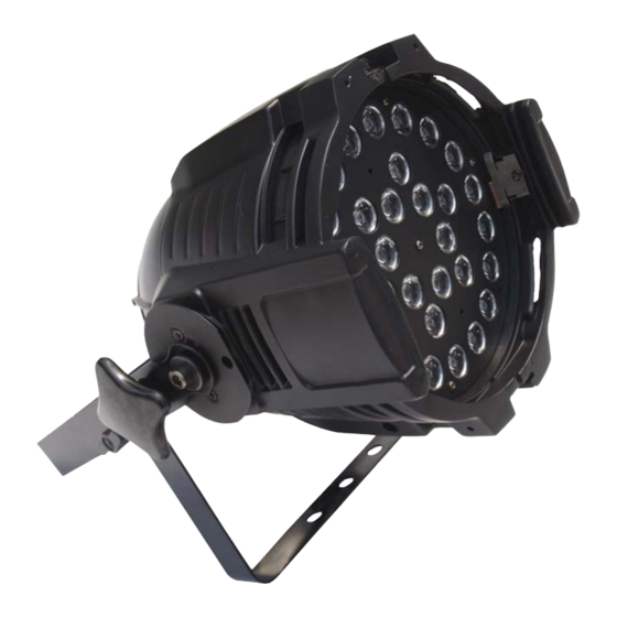
Specifications Fixture Overview • RGBW color mixing with intensity and strobe effects • 30 x 1 watt LED - 8 Red, 8 Green, 8 Blue and 6 White • Beam Angle – 15° • Rugged Aluminum Housing • Operating modes: DMX, Scene Memory, Chases, Sound Active, Master/Slave •... -
Page 5: Unpacking
Unpacking Immediately upon receipt, carefully unpack and inspect the fixture to verify that all parts are present and have been received in good condition. If any parts appear damaged from shipping or the shipping carton shows signs of mishandling, notify the shipper immediately. Retain carton and all packing material for inspection. -
Page 6: Basic Reference
Basic Reference Power/Data Indicator Digital LCD Display Audio Indicator Menu Setting Buttons Microphone Power Input Cable Fuse Holder Female XLR 5-pin Male XLR 5-pin Data Output Cable Data Input Cable This fixture includes a filter frame. This frame can be used to hold a gel or filter to better assist in controlling your light beam. -
Page 7: Control Panel Menu
Control Panel Menu The fixture’s Control Panel accesses the Control Menu. • MENU Key: activates the Menu mode, also used as a BACK key between options • UP/DOWN Keys: move through menu options and change assigned values. • ENTER Key: select a displayed menu option and store a change. Press MENU to enter the Control Menu and the UP/DOWN keys to select a menu item. -
Page 8: Dmx Channel Assignments
DMX Channel Assignments Fixture Mode (DMX512) Fixture Mode has several channel configuration options DMX512 control. Fixture Mode does not display in the standard Control Menu. To access the Fixture Mode options, before applying power, press and hold the MENU key. Continue holding the MENU key for approximately 6 seconds after applying power to the fixture. -
Page 9: Channel Mode
7 Channel Mode Channel Function Master Dimmer (0-255) Red (0-255) Green (0-255) Blue (0-255) White (0-255) Color Macro/Scroll (0-255) Strobe (0-255) Channel Values and Functions – 7 Channel Mode CH 1 : Master Dimmer The Master Dimmer controls the CH 1 – Master Dimmer actual output level while the DMX Value Function... - Page 10 CH 6 : Color Macro/Scroll The Color Macro/Scroll selects CH 6 – Color Macro/Scroll between 16 colors and two Color DMX Value Function Scroll Modes. The first Color No Macro or Scroll Scroll Mode snaps between Cool White colors, the second Color Scroll 8-11 Lt.
-
Page 11: Dmx-512 Control
DMX-512 Control Fixtures require a "Start Address" from 1 to 512, setting the first DMX channel containing data for the fixture (see DMX Background). Before addressing fixtures, consult the manual of the system’s DMX controller to select a desirable addressing scheme. Valid Start Addresses range from 1 to 512. -
Page 12: Adapter 5-To-3 Pin
Adapter 5-to-3 pin Systems using 5 pin DMX interfaces can be accommodated by purchasing 3-to-5 pin adapters or building adapter cables. Numbers designating each pin can be found on connectors. Converting between the two XLR types is done in a pin-to-pin fashion. Connect the shields to pin 1, then connect pin 2 to pin 2 and pin 3 to pin 3, regardless of either connector’s gender or pin count. -
Page 13: Maintenance
Maintenance Make sure fixture is cool and disconnected from power mains before any service. Weekly operating hours and environmental conditions will establish how often the fixtures need cleaning. Fixtures should be cleaned and inspected at least once a month to maintain optimum performance. -
Page 14: Troubleshooting
Data Negative (S- or Cold) are common in the audio industry. In either case, pin numbers are the same Data Positive (S+ or Hot) and carry the same signals. n/c (not used) n/c (not used) 10900 Palmbay Drive • Orlando, FL 32824 U.S.A. www.techni-lux.com...
Need help?
Do you have a question about the DL-FLEXILED1C30/B and is the answer not in the manual?
Questions and answers