
Related Manuals for Techni-Lux LEDifice Series


Summary of Contents for Techni-Lux LEDifice Series
- Page 1 Information specifically for: DL-LEDIF98QO V1.0 This manual contains important information. Please read before operating fixture.
- Page 2 If purchase date can not be provided, warranty period will start at manufacture date. It is the sole discretion of Techni-Lux to repair or replace parts or equipment. All shipping will be paid by purchaser. This warranty does not cover lamps, fuses,...
-
Page 3: Table Of Contents
Table of Contents Specifications ..........................4 Unpacking ...........................5 Power............................5 Mounting .............................5 Basic Reference..........................6 Setup and Operation Modes (LCD Display)................6 Control Panel Menu ........................7 DMX-512 Control.........................7 DMX Data Connection ......................8 Data Terminator ........................8 Adapter 5-to-3 pin ........................8 DMX Start Address ........................9 DMX Channel Assignments .......................9 4 Channel Mode........................9 6 Channel Mode........................10 7 Channel Mode........................10... -
Page 4: Specifications
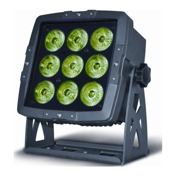
Specifications Fixture Overview • RGBW color mixing with intensity and strobe effects • 9 x Quad LEDS (rated 8W max. each) with Red, Green, Blue and White • Beam Angle – 25° • Rugged Housing • Operating modes: DMX, Static scene, Color Scroll, IR remote, Master/Slave •... -
Page 5: Unpacking
Unpacking Immediately upon receipt, carefully unpack and inspect the fixture to verify that all parts are present and have been received in good condition. If any parts appear damaged from shipping or the shipping carton shows signs of mishandling, notify the shipper immediately. Retain carton and all packing material for inspection. -
Page 6: Basic Reference
Basic Reference Power Input Cable Power Output Cable with Male 3pin Connector with Female 3pin Connector Data Input Data Output Cable Cable LCD Display Menu Setting Buttons Setup and Operation Modes (LCD Display) The following refers to the different modes that are available on this fixture via the LCD Control Panel display. -
Page 7: Control Panel Menu
Control Panel Menu Use the fixture’s Control Panel to access the Control Menu. The MODE Key puts the fixture in the settings menu itself and also acts as a BACK key between options, UP/DOWN moves through the menu options and allows the assignment of a value. The ENTER key is used to enter that option and confirms the selection once the UP/DOWN is used to adjust the value. -
Page 8: Dmx Data Connection
Note: For DMX to operate on this unit must be set to SLAVE mode. DMX Data Connection This fixture uses 3 pin XLR type connectors and shielded twisted pair cable approved for EIA-422/EIA485 use. Fixtures are connected in Daisy Chain topography: Connection is made from the controller to the DMX-IN of the first light, then from the DMX-OUT to the DMX-IN of the next light and so on. -
Page 9: Dmx Start Address
DMX Start Address To place the fixture in DMX mode, press the MENU key, then using the UP/DOWN keys get to the Address Menu Option. Press ENTER and using the UP/DOWN buttons, set the start address number for this particular unit in the DMX chain. Once selected, press ENTER again to save your selection. -
Page 10: Channel Mode
6 Channel Mode Channel Function Red (0-255) Green (0-255) Blue (0-255) White (0-255) Master Dimmer (0-255) 000-000 On – No Function 001-005 Off – No output 006-010 On 011-255 Strobe (slow to fast) 7 Channel Mode Channel Function Master Dimmer (0-255) Strobe slow to fast (0-255) Red (0-255) Green (0-255) -
Page 11: 3 : Red
CH 3 : Red Sets relative intensity of Red. CH 3 – Red Actual value is subject to Master DMX Value Function Dimmer channels. 0-255 Intensity - Off to Full On CH 4 : Green Sets relative intensity of Green. CH 4 –... -
Page 12: Remote Control Functions
Remote Control Functions This fixture includes an IR remote control that can be used to make settings and operate the unit manually. It can be used without the need for a DMX controller and in standalone applications. The remote uses IR technology to communicate with the fixture, so it is important that the remote be aimed at the light directly. -
Page 13: Maintenance
Maintenance Make sure fixture is cool and disconnected from power mains before any service. Weekly operating hours and environmental conditions will establish how often the fixtures need cleaning. Fixtures should be cleaned and inspected at least once a month to maintain optimum performance. -
Page 14: Troubleshooting
3 pin XLR connectors as these types of balanced or “Lo-Z” cables Data Negative (S- or Cold) are common in the audio industry. In either case, pin numbers are the same and Data Positive (S+ or Hot) carry the same signals. n/c (not used) n/c (not used) www.techni-lux.com...
Need help?
Do you have a question about the LEDifice Series and is the answer not in the manual?
Questions and answers