
Related Manuals for Techni-Lux DL-BAR10C252


Summary of Contents for Techni-Lux DL-BAR10C252
- Page 1 Information specifically for: DL-BAR10C252 This manual contains important information. Please read before operating fixture.
-
Page 2: Important Information
If purchase date can not be provided, warranty period will start at manufacture date. It is the sole discretion of Techni-Lux to repair or replace parts or equipment. All shipping will be paid by purchaser. -
Page 3: Table Of Contents
Table of Contents Specifications..........................4 Unpacking............................5 Power .............................. 5 Mounting ............................5 Basic Reference ..........................6 Setup & Operation Modes ......................6 Stand-alone Mode ........................6 Sound-active Mode........................6 Master / Slave Mode........................6 DMX Controlling Mode ......................... 6 DMX-512 Control Mode ........................ -
Page 4: Specifications
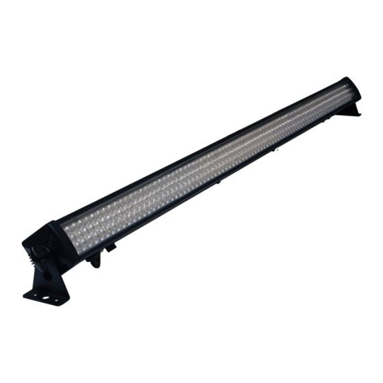
Specifications Fixture Overview • RGB color mixing with intensity and strobe effects • 252 ultra bright 10mm LEDs: 48 red, 108 green, 96 blue • Long Life LED light source • Controllable as one bar or in 3 segments of 1/3 sections •... -
Page 5: Unpacking
Unpacking Immediately upon receipt, carefully unpack and inspect the fixture to verify that all parts are present and have been received in good condition. If any parts appear damaged from shipping or the shipping carton shows signs of mishandling, notify the shipper immediately. Retain carton and all packing material for inspection. -
Page 6: Basic Reference
Basic Reference Setup & Operation Modes For this fixture to operate correctly you must first set the dip switches to the desired operation mode. This tells the fixture how it is to perform and what signals (if any) it is to respond to. When DIP Switch #10 is in the OFF position, the remaining switches Dips 1-9 can be used to set the fixture in various stand-alone modes. -
Page 7: Dmx-512 Control Mode
DMX-512 Control Mode Fixtures require a "Start Address" from 1 to 512, setting the first DMX channel containing data for the fixture (see DMX Background). Before addressing fixtures, consult the manual of the system’s DMX controller to select a desirable addressing scheme. Valid Start Addresses range from 1 to 512. -
Page 8: Dmx Start Address
5 Pin XLR (Socket) Pin 1: GND(Sheild) XLR (Plug) Pin 2: Signal(-) Pin 1: GND(Sheild) Pin 3: Signal(+) Pin 2: Signal(-) Pin 4: N/C Pin 3: Signal(+) Pin 5: N/C 5 Pin XLR (Plug) XLR (S ocket Pin 1: GND(Sheild) Pin 1: GND(Sheild) Pin 2: Signal(-) Pin 2: Signal(-) -
Page 9: Dmx Channel Assignment
DMX Channel Assignment DMX Function Table – Based on first channel The DMX channel functions in the table below depend on the value of channel 1. Channel 1 of the fixture which is also the start address, sets what the rest of the channels will do. If you wish to use this fixture in the most versatile mode, channel 1 would be set to a DMX value between 1 to 15 from your DMX controller. -
Page 10: Maintenance
Maintenance Make sure fixture is cool and disconnected from power mains before any service. Weekly operating hours and environmental conditions will establish how often the fixtures need cleaning. Fixtures should be cleaned and inspected at least once a month to maintain optimum performance. -
Page 11: Troubleshooting
In either case, pin numbers are the same and carry Data Negative (S- or Cold) Data Positive (S+ or Hot) the same signals. n/c (not used) n/c (not used) 10900 Palmbay Drive • Orlando, FL 32824 U.S.A. www.techni-lux.com...
Need help?
Do you have a question about the DL-BAR10C252 and is the answer not in the manual?
Questions and answers