Lab.gruppen PLM 20K44 Operation Manual
Plm plus series, powered loudspeaker management system
Hide thumbs
Also See for PLM 20K44:
- Operation manual (92 pages) ,
- Quick start manual (43 pages) ,
- Quick start manual (32 pages)
Table of Contents
Advertisement
Rev. 3.0
Rev. 3.0.1
Item no. QSG-PLM+SERIES
Item no. OM–PLM+
Powered Loudspeaker Management™ System
Powered Loudspeaker Management™ System
PLM+ SERIES
PLM+ SERIES
PLM 20K44
PLM 20K44
PLM 12K44
PLM 12K44
PLM 5K44
PLM 5K44
Incorporating technologies from
Incorporating technologies from
Operation Manual
Quick Start Guide
Advertisement
Table of Contents

Related Manuals for Lab.gruppen PLM 20K44


Summary of Contents for Lab.gruppen PLM 20K44
- Page 1 PLM+ SERIES PLM+ SERIES Rev. 3.0.1 Rev. 3.0 Item no. OM–PLM+ Item no. QSG-PLM+SERIES Powered Loudspeaker Management™ System Powered Loudspeaker Management™ System PLM 20K44 PLM 20K44 PLM 12K44 PLM 12K44 PLM 5K44 PLM 5K44 Incorporating technologies from Incorporating technologies from...
-
Page 2: Important Safety Instructions
1. Important safety instructions 1. Important safety instructions Before using the device, be sure to carefully read the Safety Instructions. Keep this document with the device at all times. Read these instructions. 1.1. Approvals Keep these instructions Heed all warnings. Follow all instructions. - Page 3 1. Important safety instructions To completely disconnect this equipment from the AC Radio interference mains, disconnect the power supply cord plug from the AC A sample of this product has been tested and complies with receptacle. The mains plug of the power supply cord shall the limits for the European Electro Magnetic Compatibility remain readily operable.
-
Page 4: Table Of Contents
Table of Contents Table of Contents 1. Important safety instructions 1.1. Approvals 1.2. Warnings 2. Introduction 2.1. Welcome 2.2. Main Features 2.3. Additional Documentation 3. Installation 3.1. Unpacking 3.2. Mounting 3.3. Cooling 3.4. Operating Voltage 3.5. Grounding 4. Product Overview 4.1. - Page 5 Table of Contents 7.4. Mute Enable Button 7.5. Meter Button 7.6. Menu Button 7.7. Exit Button 7.8. Dynamic Buttons, Controls and LEDs 7.9. Warning and Fault Indications 7.10. Meter Mode 7.11. Menu Mode 8. Back Panel Interface 8.1. Speaker Outputs 8.2.
-
Page 6: Introduction
2. Introduction 2.1. Welcome Thank you for choosing the Lab.gruppen PLM+ Series of Powered Loudspeaker Management systems for your For fast installation and use of this product, your welcome package includes a printed copy of the PLM+ Series Quick Start Guide which contains the information required to safely install the product and place it in service. - Page 7 2. Introduction 2.2.2.1. Amplifier Gain Amplifier Gain is set in the digital domain for PLM+ Series devices, and may be controlled via the Lake Controller software or front-panel interface. 2.2.2.2. ISVPL™ The Inter-Sample Voltage Peak Limiter (ISVPL) tailors each power output to the characteristics of the connected load.
-
Page 8: Additional Documentation
Carefully open the shipping carton and check for any damage to the device or the supplied accessories. Every Lab.gruppen product is tested and inspected before leaving the factory and should arrive in perfect condition. If any damage is discovered, please notify the shipping company immediately. Only the consignee may initiate a claim with the carrier or their insurers for damage incurred during shipping. - Page 9 3. Installation 3.2.1. Rear Mounting Two rear support brackets along with associated mounting hardware are included with the PLM+, as shown in Figure 3.1; it is recommended that these are used wherever possible. Fit the brackets to the vertical rails at the rear of the rack.
-
Page 10: Cooling
3. Installation 3.3. Cooling 3.3.1. Overview direction. space to allow air to escape. If the PLM+ is rack-mounted, never operate the unit with any front or rear rack doors or covers in position. It is recommended to keep the ambient temperature around the PLM+ as cool as possible. inside the PLM+. -
Page 11: Grounding
3. Installation If the mains plug (AC plug) fitted to the mains cable (AC cord) is not appropriate for your country, it can be removed and a locally-sourced one fitted instead, observing the color coding in the table below: powerCON pin 230 V Cable 115 V Cable Brown... -
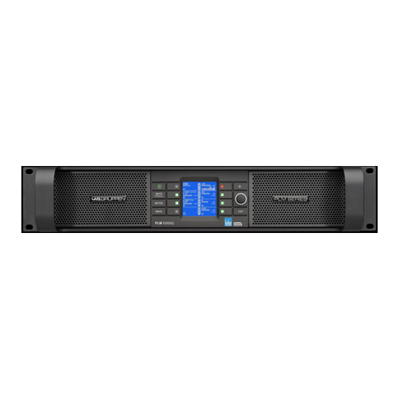
Page 12: Product Overview
4. Product Overview 4. Product Overview 4.1. Front Panel Overview The front panel presents the following amplifier status indicators: The front panel controls are clustered around a daylight readable LCD , allowing adjustment and monitoring of the majority parameters and meters. The two clusters of controls on either side of the LCD include five dedicated function buttons , eight dynamic function buttons with embedded LEDs and a rotary data... - Page 13 4. Product Overview Mute Enable – Select MUTE ENABLE to allow the dynamic function buttons to operate as mute controls for the Module inputs and power output channels. The MUTE ENABLE bu a subsequent press deselects this mode. If left activated, MUTE ENABLE mode will automatically disable two minutes after the last mute action.
-
Page 14: Rear Panel
4. Product Overview 4.2. Rear panel INPUT 1-2 INPUT 3-4 1Gbps PRIM 1Gbps 100-240V 2400-2950W SPEAKER OUTPUTS INPUT 1 INPUT 2 INPUT 3 INPUT 4 50-60Hz LINK LINK CH 1 CH 3 CH 2 CH 4 PIN 1: SCRN 2: POS 3: NEG AES/EBU SWITCHED 00/ 000 Base-TX ANALOG WITH... - Page 15 4. Product Overview Ethernet and Power Connectors Primary Network Connector – The primary Neutrik RJ45 etherCON® connection provides integration into an Ethernet control network which may include other Lake Processors and the Lake Controller software. Network connection permits full control of all functions along with real-time metering from a remote position. This device supports the Dante audio networking protocol for multichannel, high-definition digital audio over the same Ethernet connection.
-
Page 16: Operation And Performance
5.2. Power output performance The PLM20K44 and PLM12K44 use Lab.gruppen’s patented Class TD technology (Tracking Class D) in the output stages, which couples the efficiency of Class D topologies to the sonic purity of Class A/B designs. The primary benefit is that Lab.gruppen’s Class TD works perfectly under all load conditions. - Page 17 5. Operation and performance Desired power can be specified in several domains: burst and peak power; peak and RMS voltage; and also the speaker’s AES power rating. By specifying the nominal impedance of the load, the RPM algorithms have all input data required to calculate resulting RPM settings.
-
Page 18: Amplifier And Load Protection Systems
5. Operation and performance CAFÉ with ESP: CAFÉ (Configuring Amplifiers For the Environment) is a dedicated software application for Windows and OSX that provides tools for system planning, specification and commissioning. CAFÉ incorporates the Equipment Specification Predictor (ESP), a software module that examines SPL and speaker requirements for a project and generates requirements for output power on an amplifier and system level. - Page 19 5. Operation and performance Table 5.3 shows the theoretical maximum output power for a given load impedance and ISVPL setting. Max. Sinewave Burst Power (Watts) LLoad Impedance (ohms) 2.67 LISVPL SETTING (V peak) 4489 5993 4705 2352 1176 4489 5993 4656 2328 1164...
- Page 20 5. Operation and performance 5.3.3. Power Average Limiter (PAL) The Power Average Limiter Active warning (PAL Active) will be displayed when the power supply’s maximum rated design parameters are reached. When this warning is displayed, gain limiting is being applied to the output signal and the ISVPL threshold is lowered accordingly.
- Page 21 5. Operation and performance 5.3.6. Current Average Limiter (CAL™) The Current Average Limiter (CAL) monitors the RMS current drawn from each power output channel to ensure that the power output stages are not overloaded. When activated, it regulates the current to a safe level to protect the channel.
- Page 22 Lake Controller and CAFÉ status views on the PLM 12K44 and PLM 20K44. For the PLM 5K44, there is no fault displayed in this instance, but no signal will be present on the output.
- Page 23 5. Operation and performance Trigger voltage Frequency [kHz] Fig 5.4: VHF Protection Frequency Sensitivity The attack time of the VHF protection circuitry also changes with frequency, becoming shorter at higher frequencies. This is shown in Figure 5.5. Full output voltage 1400 1200 1000...
-
Page 24: Power Supply
5. Operation and performance 5.3.12. Power supply protection The power supply is very advanced and has several internal control and monitoring functions. Should any of these fail, the power supply will shut down to prevent damage or limit severity of the failure. Power supply faults, or power supply needs service faults, are indicated by flashing red on the frame LEDs and a corresponding text description on the front panel, in Lake Controller and CAFÉ... -
Page 25: Loadpilot Load Monitoring
5. Operation and performance 5.4.1. Low Inrush Current High power amplifiers with inadequate inrush current limiting can draw considerable current from the mains at turn–on, sometimes tripping a fast–acting mains breaker. The PLM+, however, has very low inrush current to prevent tripping of breakers. - Page 26 5. Operation and performance • If there are one or two “spurs” with 70V loudspeakers connected; if two in parallel is default, it will warn if one is missing. • If there is a short circuit in the load. • If there is an open circuit (all loudspeakers missing). •...
- Page 27 NOTE: Manual configuration of LoadPilot is implemented in CAFÉ versions 1.1.0. and later. For detailed information on manual configuration of LoadPilot, please refer to the integrated guide in the software program and to the CAFÉ Coach videos posted on the Lab.gruppen web site and on the Lab.gruppen channel on YouTube.
-
Page 28: Signal Flow And Lake® Processing
6. Signal Flow and Lake® Processing 6. Signal Flow and Lake® Processing 6.1. Signal Flow The figures below depict the audio signal flow for a PLM+ Series device. It is worth noting that this sophisticated device provides seven points in the signal chain where the signal level can be adjusted, muted or disconnected. The blue sections represent Frame data, and the red sections represent Module data - please refer to the Lake Controller Operation Manual for further information. -
Page 29: Level Adjustments & Mute Points
6. Signal Flow and Lake® Processing 6.2. Level Adjustments & Mute Points 1 Input Router Stage Input selection and MUTE 2 Input Mixer Stage Router on /off connection to mixer and gain settings 3 Module Input Stage Mute (N/A for LM Series Mesa Mode) and gain settings 4 Module Output Stage Mute and gain settings 5 Output Router Stage... -
Page 30: Lake Processing And Control
6. Signal Flow and Lake® Processing 6.3. Lake Processing and Control As outlined in section 2.2.3, this device integrates seamlessly into the Lake Processing environment, providing all features, functionality and connectivity associated with all Lake Processors. The internal Lake Processing includes programmable crossovers, EQ, dynamics and other functions, and can be fully controlled via the Lake Controller software with a version number of 6.3 or later. -
Page 31: Loudspeaker Processor Overview
6. Signal Flow and Lake® Processing 6.5. Loudspeaker Processor Overview The Lake Processing system within PLM+ Series devices may be configured with up to four processing Modules containing a total of up to twelve processing Module outputs, that can be routed to any of the four power output channels. -
Page 32: Front Panel Interface
7. Front Panel Interface 7. Front Panel Interface An overview of the front panel interface is provided in section 4.1. This chapter describes each cluster of controls as shown in the diagram below. 7.1. Overview The front panel interface is framed by two sturdy cast aluminium handles and metal grill protecting the air intake and dust filters . -
Page 33: Front Panel Key Lock
7. Front Panel Interface 7.1.3. Selecting a Module in the Lake Controller software via the Front Panel It is sometimes useful to identify which Module icon/s in the Lake Controller software are associated with a particular hardware Frame. To highlight the module in the Lake Controller software: 1. -
Page 34: Mute Enable Button
7. Front Panel Interface 7.4. Mute Enable Button The dynamic function buttons to the immediate left and right of the LCD are used as MUTE buttons only when the MUTE ENABLE button is activated (flashing). When MUTE ENABLE is activated the MUTE ENABLE button will flash and the four buttons on the left act as Module or Input Router mute controls (depending on active view) and the four buttons on the right enable muting/unmuting of the Amplifier Channel (power outputs). -
Page 35: Dynamic Buttons, Controls And Leds
7. Front Panel Interface 7.8. Dynamic Buttons, Controls and LEDs Figure 7.3: LCD with Dynamic Buttons, Controls and LEDs 7.8.1. Communication LED This bright white LED signifies selection in the Lake Controller, or Controller communication providing visual confirmation of: 1. Network communication between the Lake Controller and the Lake Processor (Flashing LED). 2. - Page 36 7. Front Panel Interface 7.8.3. Rotary Encoder The rotary encoder is used to adjust parameters in conjunction with the selection made via the dynamic function buttons and LCD menus. The ring around the rotary encoder illuminates when a selected parameter is available for adjustment.
- Page 37 7. Front Panel Interface 7.8.4.1. Mute Functions The PLM+ provides mute functions at several different points in its audio chain. Please refer to section 6.1 for further information. The four types of mute are: 1. PLM+ Input Router Mute 2. Module Input Mute 3.
- Page 38 7. Front Panel Interface NOTE: Fault condition LED indications take priority over mute status indications. If a fault condition occurs, the LED will indicate the fault by flashing and will note the mute status. When a Frame fault is active the audio on all channels is muted. Module Input Mutes may also be controlled in Menu Mode.
- Page 39 7. Front Panel Interface 7.8.5. LED Fault, Warning and Clip Indication A tricolor LED is embedded inside each of the eight dynamic function buttons. The LEDs convey a variety of status indications including faults and warnings, signal clip indications, Module input mute, Module output mute and Power Output mute.
-
Page 40: Warning And Fault Indications
7. Front Panel Interface 7.8.5.2. Warning or Fault Indications If certain parameters within the PLM+ approach or exceed preset limits, a warning condition or fault condition may arise. One or more LEDs provide a visual indication of the problem, along with an on-screen description of the condition displayed adjacent to the LED/s. - Page 41 7. Front Panel Interface On Screen Warning Text Type LED No. Warning Event Log Text AMP CH. MUTE Channel Fault/Clip Mute Amp Channel Mute TEMP FLT:CH Channel Amp Temp Fault Temp Fault: Amp Channel CHECK AC MAINS Frame Check AC Mains Frame Fault: Check AC Mains CAL ACTIVE Channel...
-
Page 42: Meter Mode
7. Front Panel Interface 7.10. Meter Mode 7.10.1. Home View The default view when powering on the device is Meter Mode > Home View as shown in Figure 7.7. Figure 7.7: Meter Mode > Home View Home View provides a summary of Module I/O gain level and limiter gain reduction, along with frame, module and channel labeling information. - Page 43 Bridge Mode, as shown in Figure 7.8 For further information on Bridge Mode, please refer to section 8.1.1. Figure 7.8: Standard and Bridge Mode Front Panel Icons (only for PLM 12K44 and PLM 20K44) Bridge Mode is visible via this icon notation on the PLM+ Front Panel in Home View, however, the Lake Controller information.
- Page 44 7. Front Panel Interface LoadPilot Status: 1. High Freq Pilot tone Enabled/Disabled, 2. Low Freq Pilot tone Enabled/Disabled, Status LoadPilot Status: 1. High Freq Pilot tone Enabled/Disabled, 2. Low Freq Pilot tone Enabled/Disabled, Status LoadPilot Status: 1. High Freq Pilot tone Enabled/Disabled, 2. Low Freq Pilot tone Enabled/Disabled, Status Current View title &...
- Page 45 7. Front Panel Interface 7.10.4. Input Meters View Input View enables inspection of the source selected to each input router; input signal level before the input mixer (i.e. prior to the Home View Module input meters); Module Input Mixer Routing; as well as Input Connection status. Figure 7.11: Meter Mode >...
-
Page 46: Menu Mode
7. Front Panel Interface Output 1: Output Label - Output Gain Meter - Lx: Sum of Lake MAX-Peak and MAX-RMS gain reduction Output 2: Output Label - Output Gain Meter - Lx: Sum of Lake MAX-Peak and MAX-RMS gain reduction Output 3: Output Label - Output Gain Meter - Lx: Sum of Lake MAX-Peak and MAX-RMS gain reduction Output 4: Output Label - Output Gain Meter - Lx: Sum of Lake MAX-Peak and MAX-RMS gain reduction Current View title &... - Page 47 7. Front Panel Interface 7.11.1.1. Parameters with Individual Values and Group Totals The following parameters display two values: • MODULE > GAIN • MODULE > DELAY • MODULE > LIMITERS > MAXRMS LEVEL • MODULE > LIMITERS > MAXPEAK LEVEL The Module parameter can be adjusted using the rotary encoder.
- Page 48 7. Front Panel Interface • LOAD MONITOR (See section 7.11.8) • Configure No. of Cabinets in Parallel • LoadSmart Verification • Estimated No. of Cabinets 7.11.2. Module Submenu Only module output channels for routed Power channels are displayed. This applies to all module output configurations described below.
- Page 49 7. Front Panel Interface 7.11.2.2. Gain MENU > MODULE > GAIN Figure 7.16: Module Gain Edit Screen Press the illuminated button next to the module input/s and/or output/s for adjustment, and use the rotary encoder to change the value(s). Multiple gain values may be adjusted simultaneously in 0.1 dB increments, subject to defined level limits.
- Page 50 7. Front Panel Interface 7.11.2.5. Amp Gain MENU > MODULE > AMP GAIN By default, all outputs are selected; use the rotary encoder to change the gain of all power outputs or press the associated output button to deselect one or more outputs. Amp Gain adjusts the gain of the PLM+’s power output stage for each output channel.
- Page 51 7. Front Panel Interface MaxRMS Level (MaxRMSLvl) This sets the maximum RMS signal level at the Module outputs. It is adjustable from -30 dBu to +30 dBu in 0.1 dB increments, subject to user-defined level limits. The Group total is displayed (in brackets) for each channel. MaxRMS Corner (MaxRMSCor) A soft-knee or hard-knee corner may be applied to the RMS Limiter.
- Page 52 7. Front Panel Interface 7.11.3. I/O Configuration MENU > I/O CONFIG Figure 7.17: I/O Configuration Sub Menu This menu provides configuration options for input routing, along with settings for AES Termination and Iso-Float as described in the following sections. 7.11.3.1. Input Router Configuration MENU >...
- Page 53 7. Front Panel Interface With a router selected on the front panel, press the middle button on the left of the LCD to activate this parameter for editing. Use the illuminated rotary encoder to scroll through the following options: • Auto Select (default) •...
- Page 54 7. Front Panel Interface The PLM+ device at the end of a distribution line should be set to TERMINATED; all other PLM+ devices should be set to UNTERMINATED. If an AES3 distribution amplifier (DA) is being used to distribute the digital audio signals, with one DA output per processor, then all terminations should be on.
- Page 55 7. Front Panel Interface Toggle the Source from which you want to route the channels (Module, Analog, AES) (NOTE: that this also may affect the destination, as only AES3 and analog can be routed to Dante. Toggle up among the available source channels Toggle down among the available source channels Unused Unused...
- Page 56 7. Front Panel Interface 7.11.5.1. Frame Info MENU > FRAME > FRAME INFO Firmware Version (FW Version) Further internal version numbers are displayed on right side of screen; Bundle, DSP, FPGA and Safe Image version. Serial Number (Serial No.) The printed serial number on the back panel of the PLM+ is also electronically embedded in the hardware, and therefore cannot be removed or altered if stolen.
- Page 57 7. Front Panel Interface 7.11.5.3. Breaker Emulation Limiter MENU > FRAME > BEL CONF The Breaker Emulation Limiter (BEL) provides Ampere selection (5-32 A) and breaker type selection (CONSERVATIVE, FAST and UNIVERSAL). Select by pressing the adjacent button then use the rotary encoder to change the parameter.
- Page 58 7. Front Panel Interface 7.11.6. Front Panel Display Controls MENU > FRAME > FRONT Contrast To adjust the front panel LCD contrast, select this option then use the rotary encoder to change the value. Dimming To adjust the front panel LCD & LED brightness, select this option then use the rotary encoder to change the value. Channel Order To adjust the order in which both inputs and outputs are displayed on the front panel in all views, select this option then use the rotary encoder to change the value between TOP-DOWN (default) and BOTTOM-UP.
- Page 59 7. Front Panel Interface 7.11.8.1. Configure # of Cabinets in Parallel This option allows selection of the number of speaker cabinets connected to each PLM+ output channel. Select individual or multiple outputs and use the rotary encoder to set the value from 1 to 4. This value is used by LoadSmart to confirm the correct connection and status of the speakers connected to each PLM+ channel.
-
Page 60: Back Panel Interface
8. Back Panel Interface 8. Back Panel Interface An overview of the back panel interface is provided in section 4.2. This chapter describes each cluster of connections as shown in Figure 8.1. 1Gbps PRIM 1Gbps 100-240V 2400-2950W SPEAKER OUTPUTS INPUT 1 INPUT 2 INPUT 3 INPUT 4... - Page 61 8. Back Panel Interface 8.1.2. speakON Connectors Power outputs are available simultaneously on a single 8-pole connector (PLM 20K44 and PLM 12K44 only) and on two 4-pole connectors. The four-pole connectors carry outputs for channels 1&2 and 3&4 respectively. For PLM 5K44, connector 1 carries output channels 1 and 2, connector 2 carries channel 2, connector 3 carries channel 3 and 4, and connector 4 carries channel 4.
- Page 62 8. Back Panel Interface PLM+ Output PLM+ Output PLM+ Output Channels 1 & 2 Channels 1 - 4 Channels 3 & 4 8.1.3. Binding Post Connectors SPEAKER OUTPUTS CH 1 CH 3 CH 2 CH 4 CLASS 3 WIRING SPEAKER OUTPUTS CH 1 CH 3 CH 2...
-
Page 63: Analog Inputs
8. Back Panel Interface Connect the ‘+’ loudspeaker terminals to the red binding posts and the ‘ – ‘ terminals to the black binding posts. There are three methods of connecting speaker cables to the binding posts. 1. Solder 4 mm banana-plugs to the ends of the speaker wires and plug into the center of the turrets. 2. - Page 64 8. Back Panel Interface 8.2.3. Unbalanced Operation Balanced connections are recommended where possible. However, if it is necessary to drive the device from equipment with an unbalanced output, wire the inputs as shown in Figure 8.10. COLD COLD SCRN SCRN Unbalanced Output Balanced Input (Typically phono)
-
Page 65: Aes3 Digital Inputs
8. Back Panel Interface 8.3. AES3 Digital Inputs 8.3.1. AES3 XLR Connector AES3 digital audio input is via two XLR3F connectors. Connectors are provided for Inputs 1 & 2 and Inputs 3 & 4. Wiring of this connector follows the same standard as for analog XLR connections as shown section 8.2.2. The AES3 signal format carries two channels of audio and associated data on a single cable/connector. - Page 66 8. Back Panel Interface Pin No. Color Brown Brown + White Green Blue + White Blue Green + White Orange Orange + White Table 8.14: RJ45 Wiring & Pin Out Description Figure 8.15: RJ45 Wiring & Pin Out Diagram When the device is connected to an active network, the yellow LINK LED illuminates above the connector in use. Data activity on the network is indicated by illumination of the green ACT LED.
-
Page 67: Power Inlet
8. Back Panel Interface 8.5. Power Inlet 8.5.1 Power Connector A Neutrik NAC3 Series powerCON connector rated at 32 A is fitted to the rear of the PLM+ for AC mains input. The power cable (AC cord) supplied with the PLM+ has the mating connector ready-fitted, but may require a mains (AC) plug specific to your country to be fitted to the other end. -
Page 68: Appendix
9. Appendix 9. Appendix 9.1. Faults and Warnings Overview Category/Type Name On screen text Description Action FRAME Check network cabling/ CTRL OFFLINE network if controller Warning on the network expected on the network Frame not able to lock to Check AES sender and AES clock slipping CLOCK SLIPPING Warning... - Page 69 9. Appendix Category/Type Name On screen text Description Action The Under Voltage limiter is active as the mains supply is approaching the lower Increase mains distribution Under Voltage Limit UVL ACTIVE end of the device´s operational voltage. stiffness or reduce output Warning Output power is decreased to ensure power to avoid limiting...
- Page 70 9. Appendix Category/Type Name On screen text Description Action LoadSmart detected more speakers Check load and More speakers OVR SPKR COUNT Warning than expected Check load and Uncertain about load UNCERTAIN LOAD LoadSmart uncertain about load Warning Perform LoadSmart LOAD NOT VER Warning At least one LoadPilot tone above No load...
-
Page 71: Maintenance
9. Appendix 9.2. Maintenance During normal operation this devices provides trouble-free service. If the LCD or front panel display requires cleaning, use a soft cloth only; do not use solvent cleaners. T turning the unit back on. In extreme cases it may be necessary to clean the inside of the device. This procedure should only be carried device has had prolonged operation in an extreme environment such as one where cracked oil smoke machines are in use. - Page 72 9. Appendix 9.3.2. Input and Router Defaults Autoselect: Input sensitivity: +26 dBu Dante: Disabled AES3: Terminated Iso-Float: Enabled Router 1: Priority 1 = Dante Receiver (Ch.1) Priority 2 = Dante Receiver (Ch.5) Priority 3 = AES1 (Ch.1) Priority 4 = Analog 1 Router 2: Priority 1 = Dante Receiver (Ch.2) Priority 2 = Dante Receiver (Ch.6)
-
Page 73: Standby Mode
9. Appendix 9.4. Current Draw and Thermal Dissipation Specifications different operating conditions for each PLM+ Series device. 1. Standby Mode 2. Power On (Idle - No Signal) 3. Power On (Normal Operation - Pink Noise 1/8 of Rated Power) 4. Power On (Heavy Duty Operation - Pink Noise Max Power) 5. - Page 74 9. Appendix PLM 12K44 Rated power Power Level Load Line Current Measured Power (W) Thermal Dissipation per channel Factor Dissipated BTU/hr kCal/hr Mains Voltage 100 VAC, 30 A Standby Power on, Idling / Ch. 10.8 1059 1994 / Ch. 1900 19.2 1868 3136...
- Page 75 9. Appendix PLM 20K44 Rated power Power Level Load Line Current Measured Power (W) Thermal Dissipation per channel Factor Dissipated BTU/hr kCal/hr Mains Voltage 100 VAC, 30 A Standby Power on, Idling / Ch. 1150 12.1 1192 2061 / Ch.
-
Page 76: Glossary Of Terms, Acronyms And Abbreviations
Iso-Float is Lake’s proprietary method of electronic balancing, which provides a particularly high level of isolation and immunity from ground loops. ISVPL is an abbreviation for Inter-Sample Voltage Peak Limiter, a proprietary Lab.gruppen technique for ensuring that voltage at the output terminals of a PLM+ ISVPL or for universal use. - Page 77 Short Circuit Protection A Lab.gruppen proprietary protective circuit designed to mute a channel when a short circuit is detected at its output terminals to prevent damage to the device. Once activated, SpeakerSafe constantly monitors the voltage and current at the PLM+’s outputs. Using Fingerprint data, the software then calculates parameters SpeakerSafe such as voice coil and magnet temperatures, providing the operator with real-time performance monitoring.
-
Page 78: Application Guide
9. Appendix 10. Application Guide This chapter describes the practical application and use of PLM+ Series devices. 10.1. Rack I/O Panels For fast and simple system connection, pre-wired racks using connection panels can be used. With an I/O at one position, without requiring rear panel access. 10.2. -
Page 79: Gain / Level Optimization
10. Application Guide 10.2.4. Module Output Gain Factory and User Gain are provided for each Module output. These two stages provide a level of security and control for the system designer (Factory) and a further level of adjustment for the user (User), both of which 1. - Page 80 10. Application Guide 10.3.2. Minimize Noise To help provide the best volume to noise ratio, use an AES or Dante digital input signal wherever possible. If using analog inputs, ensure that unused or unnecessarily high headroom is not introduced at the input to the device. If full or high average power is not required, the Module input gain may be reduced.
- Page 81 10. Application Guide The improvement in noise performance (at the cost of losing headroom and compression features) is only 0.6 dB; it is therefore not recommended to optimize performance in this manner. 10.3.3.2. Analog Input Gain Structure Examples Figure 10.4 illustrates how to minimize absolute noise while limiting the available SPL. Input Clip: 12 dBu •...
- Page 82 10. Application Guide Figure 10.6 illustrates how moderate noise with extreme SPL can be achieved. SPL is extremely high in this example as maximum headroom is available at the input and within the processing stage. This makes it possible to increase the average SPL by utilizing internal compression capabilities.
-
Page 83: Digital Audio Connections
10. Application Guide 10.5. Digital Audio Connections Whenever possible, it is preferable to connect a digital rather that analog input signal to the device. This is particularly relevant if the source signal is already in the digital domain, such as the source from a digital mixing console or digital distribution system. - Page 84 10. Application Guide 10.5.3. Connections and Cabling 10.5.3.1. AES Input Connectors Two AES-3 input signals (each carrying two audio channels) are connected to the XLR3F connectors labelled INPUT 1-2 and INPUT 3-4 in the AES/EBU (AES-3) input section on the rear panel. Note that the Input connector types are identical for the analog and digital inputs, so care must be taken when connecting audio, particularly when analog inputs are used as a backup signal source.
- Page 85 10. Application Guide It is recommended that all cables be tested for error-free performance at lengths 20% to 25% greater than lengths 10.5.4. External Signal Distribution Hardware 10.5.4.1. Distribution Amplifiers format is one input and six outputs. Digital distribution ampli as well making up for line losses.
- Page 86 10. Application Guide 10.6. Digital Clock Configuration 10.6.1. Digital Clock Overview clocking system. The digital clock can generate various independent internal sample rates, or can sync to an incoming AES3 signal. Figure 10.7 shows the various sample rates and options available. INPUTS OUTPUTS INTERNAL...
- Page 87 10. Application Guide For Automatic Detection, the most appropriate clock matching the selected base-rate is automatically selected according to the following priorities. 1. AES1 (Input 1+2) 2. Internal Clock When using automatic detection, the AES3 digital input is monitored and will switch the clock source back and forth depending on the availability of an AES3 signal.
- Page 88 11. Technical Specifications 11. Technical Specifications General Processing / Network Lake / Dante Numbers of amplifier channels Total burst power all channels (share among channels with RPM) 5000 W Max. Output Power (all ch.’s driven) 2 ohms 900 W 2.67 ohms 1250 W 4 ohms 1250 W...
- Page 89 Intercooler, Class TD and Lake are national and/or international registered trademarks of Lab.gruppen AB. PLM, Powered Loudspeaker Management, R.SMPS, LoadLibrary, LoadSmart, SpeakerSafe, BEL, UVL and ISVPL are trademarks of Lab.gruppen AB. Dolby and the double-D symbol are registered trademarks of Dolby Laboratories. Contour, Mesa Quad EQ, Mesa Parametric EQ, Raised Cosine Equalization, LimiterMax and Iso-Float are trademarks of Dolby Laboratories.
-
Page 90: Warranty And Support
Lab.gruppen dealer. If the product fails to perform as specified during the warranty period, Lab.gruppen will undertake to repair, or at its option, replace this product at no charge to its owner, provided the unit is returned undamaged, shipping prepaid, to an authorized service facility or to the factory. - Page 91 12. Warranty and Support 12.3.2. Factory Service In the event a Lab.gruppen product requires factory service, you may contact Lab.gruppen’s service department for return instructions and a Return Authorization number. Please note for product return: 1. Use the original packing.
- Page 92 Intercooler, Class TD and Lake are national and/or international registered trademarks of Lab.gruppen AB. PLM+, Powered Loudspeaker Management, R.SMPS, LoadLibrary, LoadSmart, SpeakerSafe, ISVPL, BEL, UVL and CAL are trademarks of Lab.gruppen AB. Dolby is a registered trademark of Dolby Laboratories. Raised Cosine Equalization, LimiterMax and Iso-Float are trademarks of Dolby Laboratories.
Need help?
Do you have a question about the PLM 20K44 and is the answer not in the manual?
Questions and answers