Table of Contents
Advertisement
Quick Links
Advertisement
Table of Contents

Related Manuals for Black Horse Model Tornado BH17


Summary of Contents for Black Horse Model Tornado BH17
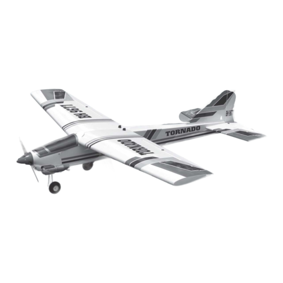
- Page 1 Instruction Manual book ITEM CODE BH17 SPECIFICATION Wingspan : 1,460 mm 57.5 in. Length 1,270 mm 50 in. Weight 2.6 kg 5.7 Lbs. Radio 04 channels.
-
Page 2: Parts List
TONADO- Item code: BH17. Instruction Manual This instruction manual is designed to help you build a great flying aeroplane. Please read this manual thoroughly before starting assembly of your TORNADO. Use the parts listing below to identify all parts. WARNING. Please be aware that this aeroplane is not a toy and if assembled or used incorrectly it is capable of causing injury to people or property. -
Page 3: Safety Precaution
TONADO- Item code: BH17. Instruction Manual SAFETY PRECAUTION. + This is not a toy + Be sure that no other flyers are using your radio frequency. + Do not smoke near fuel + Store fuel in a cool, dry place, away from children and pets. - Page 4 TONADO- Item code: BH17. Instruction Manual Electric wire. 2. Using a modeling knife, remove the cov- ering servo tray. 5. Instal servo tray with aileron servo into the wing as same as picture below. Wing. Servo tray. Servo tray. 2x10mm.
- Page 5 TONADO- Item code: BH17. Instruction Manual INSTALLING THE AILERON CONTROL HORN. Nilon control clasp. M3 lock nut. 3x40mm. 1. Using a ruler & pen to draw a straight aileron 3. Install control horn as same as line as below picture. picture below.
-
Page 6: Installing The Aileron Linkages
TONADO- Item code: BH17. Instruction Manual Bend and cut after. 4. Locate one nylon servo arm, and using wire cutters,remove all but one of the arms. Using a 2mm drill bit, enlarge the third hole out from the center of the arm to accommodate the aileron pushrod wire. -
Page 7: Joining The Wing Halves
TONADO- Item code: BH17. Instruction Manual Aluminium brace. C/A glue Top side. Epoxy glue. JOINING THE WING HALVES. 1. Locate the aluminium wing dihedral brace. 2. Using a modeling knife, remove the covering wing. Mark point. 3. Test fit the dihedral brace into each wing half. - Page 8 TONADO- Item code: BH17. Instruction Manual 8. Feed three lines through the fuel tank compartment and through the pre-drilled hole in the firewall. Pull the lines out from behind the engine, while guiding the fuel tank into place. Push the fuel tank as far forward as possible, the front of the tank should just about touch the back of the firewall.
-
Page 9: Installing The Engine Mount
TONADO- Item code: BH17. Instruction Manual INSTALLING THE ENGINE MOUNT. 3x20mm. Install the wheel and collar. Secure. INSTALLING THE ENGINE. INSTALLING THE NOSE GEAR. Locate the long piece of wire used for the throttle pushrod. One end of the wire has been pre-bend in to a “Z”... - Page 10 TONADO- Item code: BH17. Instruction Manual COWLING. 1. Slide the fiberglass cowl over the en- gine and line up the back edge of the cowl with the marks you made on the fuselage. Trim and cut Secure. Left side. Trim and cut Right side.
-
Page 11: Installing The Spinner
TONADO- Item code: BH17. Instruction Manual INSTALLING THE SPINNER. Bottom side. Install the spinner backplate, propeller and 2. While keeping the back edge of the spinner cone. The spinner cone is held in cowl flush with the marks, align the front of place using two 3mm x 15mm wood screws. -
Page 12: Installing Landing Gear
TONADO- Item code: BH17. Instruction Manual 1. The blind nuts are already mounted INSTALLING LANDING GEAR. inside the fuselage. 2. The holes in the landing gear should be to accept the mounting bolts. 3. Using the hardware provided, mount the main landing gear to the fuselage. -
Page 13: Horizontal Stabilizer Installation
TONADO- Item code: BH17. Instruction Manual HORIZONTAL STABILIZER INSTALLATION. 1. Using a modeling knife, cut away the covering from the fuselage for the stabilizer and remove it. ELEVATOR INSTALLATION. Remove covering. SERVO INSTALLATION. 1. Install the rubber grommets and brass collets into the elevator servo. - Page 14 TONADO- Item code: BH17. Instruction Manual Bottom side C/A glue. 4. Remove the stabilizer. Using the lines Bottom side. you just drew as a guide, carefully remove the covering from between them using a modeling knife. When cutting through the covering to remove it, cut with only enough pressure to only cut through the covering it’s self.
-
Page 15: Elevator Control Horn Installa- Tion
TONADO- Item code: BH17. Instruction Manual 5. When you are sure that everything is Control horn of elevator. aligned correctly, mix up a generous amount of 30 minute epoxy. Apply a thin layer to the top and bottom of the stabilizer mounting area and to the stabilizer mounting platform sides in the fuselage. -
Page 16: Elevator Pushrod Installation
TONADO- Item code: BH17. Instruction Manual Elevator pushrod. Elevator Elevator pushrod. pushrod. Bottom side. Top side. ELEVATOR PUSHROD INSTALLATION. Secure. Elevator pushrod install as same as the way of aileron pushrod. -
Page 17: Vertical Stabilizer Installation
TONADO- Item code: BH17. Instruction Manual Cut. Elevator servo. Bend and cut. VERTICAL STABILIZER INSTALLATION. Secure. Hinge. - Page 18 TONADO- Item code: BH17. Instruction Manual 1) Using a modeling knife, remove the covering from the top of the fuselage and the covering from over the precut hinge slot cut into the lower rear portion of the fuselage This slot accepts the lower vertical.
- Page 19 TONADO- Item code: BH17. Instruction Manual Epoxy glue. Epoxy glue. 5. Put the vertical stabilizer back in place. Using a triangle, check to ensure that the vertical stabilizer is aligned 90 degree to the horizontal stabilizer. Vertical Stabilizer. C/A glue 90º...
-
Page 20: Rudder Pushrod Installation
TONADO- Item code: BH17. Instruction Manual Rudder mark point control horn. Rudder pushrod. Drill 6mm diameter a hole of the mounting rudder control horn on to the rudder. Elevator Elevator pushrod. pushrod. Rudder pushrod. RUDDER PUSHROD INSTALLATION. Rudder pushrod install as same as the way of aileron pushrod. -
Page 21: Installing The Throttle Pushrod
TONADO- Item code: BH17. Instruction Manual INSTALLING THE THROTTLE PUSHROD. 1. Install one adjustable metal connector through the third hole out from the center of one servo arm, enlarge the hole in the servo arm using a 2mm drill bit to accommodate the servo connector. -
Page 22: Installing The Receiver And Battery
TONADO- Item code: BH17. Instruction Manual Nose gear pushrod. INSTALLING THE RECEIVER AND BATTERY. Rudder pushrod. 1. Plug the servo leads and the switch lead into the receiver. You may want to plug an aileron extension into the receiver to make plugging in the aileron servo lead easier when you are installing the wing . -
Page 23: Wing Attachment
TONADO- Item code: BH17. Instruction Manual BALANCING. 1) It is critical that your airplane be bal- anced correctly. Improper balance will cause your plane to lose control and crash. THE CENTER OF GRAVITY IS LOCATED 110-115MM BACK FROM THE LEADING EDGE OF THE WING. -
Page 24: Control Throws
TONADO- Item code: BH17. Instruction Manual CONTROL THROWS. 1. We highly recommend setting up a plane using the control throws listed. 2. The control throws should be measured at the widest point of each control surface.
Need help?
Do you have a question about the Tornado BH17 and is the answer not in the manual?
Questions and answers