Table of Contents
Advertisement
Quick Links
Advertisement
Table of Contents

Related Manuals for Magtrol DSP7000


Summary of Contents for Magtrol DSP7000
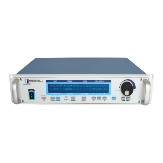
- Page 1 Model DSP7000 High Speed Programmable Dynamometer Controller User’s Manual...
- Page 2 While every precaution has been exercised in the compilation of this document to ensure the accuracy of its contents, Magtrol, Inc. assumes no responsibility for errors or omissions. Additionally, no liability is assumed for any damages that may result from the use of the information contained within this publication.
-
Page 3: Safety Precautions
Safety Precautions 1. Make sure that all Magtrol dynamometers and electronic products are earth-grounded, to ensure personal safety and proper operation. 2. Check line voltage before operating the DSP7000. 3. Make sure that dynamometers and motors under test are equipped with appropriate safety... -
Page 4: Revisions To This Manual
The contents of this manual are subject to change without prior notice. Should revisions be necessary, updates to all Magtrol User’s Manuals can be found at Magtrol’s web site at www.magtrol.com/support/manuals.htm. Please compare the date of this manual with the revision date on the web site, then refer to the manual’s Table of Revisions for any changes/updates that have been made since this edition. - Page 5 The TS1, TS2, TR1 and TR2 Commands were added to section 7.4.7. 01/09/12 1st Edition - rev. F Driver and Tera Term location changed to Magtrol Manual 7.1.1, 7.1.2, 8.4.2 12/27/11 1st Edition - rev. E USB Driver setup updated.
-
Page 6: Table Of Contents
MANUAL oRgANIzATIoN ............................xII CoNVENTIoNS USED IN ThIS MANUAL ......................... xIII 1. introduCtion ..........................1 1.1 UNPACkINg YoUR DSP7000 ............................. 1 1.2 NEW FEATURES oF ThE DSP7000 ........................... 1 1.3 DATA ShEET ................................. 2 2. Controls ............................10 2.1 FRoNT PANEL ................................10 2.2 FRoNT PANEL CoNTRoLS AND bUTToNS ...................... - Page 7 3.3 ToRqUE FILTER SETUP ............................33 3.4 INSTRUMENTATIoN SETUP (SPEED) ........................33 3.4.1 TACh A ................................35 3.4.2 qUAD DEg ..............................35 3.4.3 AI 1................................. 35 3.5 CoNFIgURE CoMMUNICATIoN ..........................36 3.5.1 gPIb Address ..............................36 3.5.2 RS-232 Interface ............................36 4.
- Page 8 7. Computer Controlled operation ..................64 7.1 AboUT ThE USb INTERFACE ..........................64 7.1.1 USb Driver Setup for Windows operation System ..................64 7.1.2 Checking the DSP7000-To-PC Connection for gPIb Setup ................. 70 7.2 DATA FoRMAT ................................71 7.2.1 output Data (oD) ............................71 7.2.2 output binary Command (ob) ........................
- Page 9 8.3.2 Connection ..............................97 8.3.3 Communication Parameters ........................... 98 8.3.4 baud Rate ............................... 98 8.4 ChECkINg ThE DSP7000-To-PC CoNNECTIoN ....................98 8.4.1 gPIb Communication check.......................... 98 8.4.2 RS232 Communication Check ........................101 9. Calibration ..........................107 9.1 CLoSED-box CALIbRATIoN ..........................107 9.2 CALIbRATIoN SChEDULE ............................
- Page 10 C.6 DSP7000 DIgITAL oUTPUT ........................... 142 appendix d: additional sCale faCtor table ..............143 serviCe information ........................144 RETURNINg MAgTRoL EqUIPMENT FoR REPAIR AND/oR CALIbRATIoN ............ 144 Returning Equipment to Magtrol, Inc. (United States) ....................144 Returning Equipment to Magtrol SA (Switzerland) ....................144...
-
Page 11: Table Of Figures
Table of Figures 2. Controls Figure 2–1 Front Panel ............................10 Figure 2–2 Secondary Function Menu ........................11 Figure 2–3 Saving Function Menu ..........................11 Figure 2–4 DSP7001 Rear Panel ..........................15 Figure 2–5 DSP7002 Rear Panel ..........................15 Figure 2–6 Dynamometer Brake Output ........................15 Figure 2–7 TSC1/TSC2 Connector ...........................16 Figure 2–8 Supply 1/Supply 2 Connector .........................16 Figure 2–9 USB Connector ............................16... - Page 12 4. pid settings Figure 4–1 Open Loop Control Menu ........................38 Figure 4–2 Initial P Setting for Torque Control at 25% ...................39 Figure 4–3 High Initial P Setting for Torque Control .....................39 Figure 4–4 Initial I Setting for Torque Control ......................40 Figure 4–5 Initial D Setting for Torque Control .......................40 Figure 4–6 Initial P Setting for Speed Control at 25% ....................41 Figure 4–7 Initial I Setting for Speed Control ......................42...
- Page 13 8. optional equipment Figure 8–1 DSP7000 Top Cover ..........................86 Figure 8–2 IO Card Installation ..........................86 Figure 8–3 I/O Card Interface ..........................87 Figure 8–4 Filter Channel Setup Menu........................90 Figure 8-5 Offset and Gain Setup Menu ........................90 Figure 8–6 External Alarm Setup ..........................90 Figure 8–7 Alarm Contact Setup..........................90...
-
Page 14: Preface
This manual is intended for bench test operators who are going to use the Model DSP7000 Dynamometer Controller in conjunction with any Magtrol hysteresis, Eddy-Current or Powder brake Dynamometer, Magtrol In-Line Torque Transducer or auxiliary instrumentation. -
Page 15: Conventions Used In This Manual
Magtrol Model DSP7000 Dynamometer Controller Preface Chapter 10: ThEoRY Chapter 11: TRoUbLEShooTINg - Solutions to common problems encountered during setup and testing. Appendix A: INERTIA CoRRECTIoN - Describes the inertial effect on motor test data providing solutions for correction. Appendix b: FRoNT PANEL/DISPLAY MENU FLoW ChARTS - A visual display of various setup procedures. -
Page 16: Introduction
Introduction unpaCking your dsp7000 Your DSP7000 was packaged carefully for shipping. Please notify your carrier and Magtrol Customer Service if you believe your unit was damaged in shipping. 1. Save all shipping cartons and packaging material until you inspect the DSP7000. -
Page 17: Data Sheet
PID (proportional gain, integral and derivative) values IEEE-488 or RS-232 interface. With up to 500 readings per Fast Full-Curve Data Acquisition: Free-run to • second, the DSP7000 is ideally suited for both the test lab and locked rotor in seconds the production line. •... - Page 18 Magtrol Model DSP7000 Dynamometer Controller Chapter 1 – Introduction Specifications DSP7000 sPecIFIcatIONs MEASUREMENT CHARACTERISTICS DIMENSIONS Maximum Torque 99,999 units Width 19.0 in 483 mm Maximum Speed 199,999 rpm Height 3.5 in 89 mm Speed: 0.01% of reading from 5 rpm to 200,000 rpm Depth 12.4 in...
- Page 19 Chapter 1 – Introduction Magtrol Model DSP7000 Dynamometer Controller Specifications DSP7000 FrONt PaNel Displays Torque, Speed, Power Ready for Rack Mounting and PID Values • • • • • • • • • • • • Reset Tare Select Display Format...
- Page 20 Magtrol Model DSP7000 Dynamometer Controller Chapter 1 – Introduction System Configurations DSP7000 Hysteresis Dynamometer (HD) Motor Under Test AC Mains 7001 DYNAMOMETER CONTROLLER M-TEST No Connection DSP7001 Connected to Hysteresis Dynamometer Hysteresis Torque Transducer Brake (TM) (<1 Amp) 7001 Hysteresis Brake DYNAMOMETER (<5 Amp)/...
- Page 21 Chapter 1 – Introduction Magtrol Model DSP7000 Dynamometer Controller System Configurations DSP7000 Hysteresis Dynamometer (HD) Eddy-Current (WB) OR Powder Brake (PB) Dynamometer Motor Under Test TSC 401 Torque-Speed AC Mains Conditioner Speed DSP7002 Torque DYNAMOMETER DES Power Supply CONTROLLER Excitation...
- Page 22 DES Power Supply Excitation DES Power Supply 7002 Dynamometer M-TEST Controller DSP7002 Connected to Eddy-Current and Powder Brake Dynamometer (Tandem Setup) The USB Driver required for communication between the PC and DSP7000 is available for download at Magtrol’s website: www.magtrol.com/support/downloads.html MAGTROL...
- Page 23 Chapter 1 – Introduction Magtrol Model DSP7000 Dynamometer Controller System Configurations DSP7000 custOM MOtOr test systeM The DSP can be incorporated into a Customized Motor Test System. These PC based, turn-key systems are custom designed and built to meet specific user requirements.
- Page 24 Magtrol Model DSP7000 Dynamometer Controller Chapter 1 – Introduction Ordering Information DSP7000 OrDerINg INFOrMatION DSP7001 High-Speed Programmable Dynamometer Controller - single channel DSP7002 High-Speed Programmable Dynamometer Controller - dual channel Model Number: DSP700X – X – X CHANNEL TYPE • Single Channel •...
-
Page 25: Controls
2. Controls front panel The front panel provides a power switch, eleven control buttons, a Decrease/Increase Dial, and Vacuum Fluorescent Display (VFD). Figure 2–1 Front Panel front panel Controls and buttons The front panel controls and buttons, from left to right, are: •... -
Page 26: Enabling Secondary Functions
Magtrol Model DSP7000 Dynamometer Controller Chapter 2 – Controls 2.2.1 nabling Econdary unctionS To enable the secondary function of the double-function control buttons: 1. Press the blue ShIFT button and release it. The word “ShIFT” appears in the display: POWER... -
Page 27: How To Use Front Panel Controls And Buttons
Chapter 2 – Controls Magtrol Model DSP7000 Dynamometer Controller 2.2.3 ow to ront anEl ontrolS and uttonS 2.2.3.1 Controls/Single-Function Buttons button to use function POWER Press I to turn power ON Press O Turns power ON or OFF. to turn power OFF. -
Page 28: Vacuum Fluorescent Display (Vfd)
Magtrol Model DSP7000 Dynamometer Controller Chapter 2 – Controls 2.2.3.2 Double-Function Buttons button to use function DISPLAY BOTH Press SHIFT and release; then Displays both TSC1 and TSC2 press this button. measurments. Press this button Switches between TSC1 and TSC2 setup. -
Page 29: Contrast Settings
2.3.1 ontraSt EttingS The DSP7000 is shipped with the Contrast Setting at zero (lowest) in order to prolong display life. If it is necessary to increase the Contrast for improved readability, execute the following steps: 1. Press ShIFT. 2. Press SETUP button. -
Page 30: Rear Panel
Magtrol Model DSP7000 Dynamometer Controller Chapter 2 – Controls rear panel The rear panel provides connectors and receptacles for connecting to appropriate equipment. Figure 2–4 DSP7001 Rear Panel ... -
Page 31: Figure 2-7 Tsc1/Tsc2 Connector
Chapter 2 – Controls Magtrol Model DSP7000 Dynamometer Controller TSC1/TSC2 Connect torque signal cable here. 1. FLOW/CLUTCH 8. +5.0 VDC COM 2. TACH. B 9. D.P. A 3. +24 VDC 10. TACH. A 4. +24 VDC COM 11. NC 5. -
Page 32: Optional Io
Magtrol Model DSP7000 Dynamometer Controller Chapter 2 – Controls 2.4.2 Ptional 1. Io Card 1 and Io Card 2 1. DAC 1 14. DAC 1 common Analog Torque OR user DAC 1 2. DAC 2 15. DAC 2 common Analog Speed OR user DAC 2 3. -
Page 33: Optional Gpib
Chapter 2 – Controls Magtrol Model DSP7000 Dynamometer Controller 2.4.3 gPib Ptional 1. D1 13. D5 14. D6 2. D2 3. D3 15. D7 16. D8 4. D4 17. REN 5. E01 6. DAV 18. DAV-COM 19. NRFD-COM 7. NRFD 8. -
Page 34: Installation/Configuration
TO rEDUCE THE riSK OF ELECTriC SHOCK, MaKE SUrE THE DSP7000 iS EarTH grOUnDED BEFOrE STarTing! 3.1.1 After turning the power on to the DSP7000, the display panel will show the message “SERIAL kEY PAD REV x.x” while the DSP7000 is downloading the program. POWER TORQUE... -
Page 35: Main Menu
Chapter 3 – Installation/Configuration Magtrol Model DSP7000 Dynamometer Controller 3.1.2 When the DSP7000 is completely powered up and ready for use, the main menu will appear on the display. POWER TORQUE SPEED USER DISPLAY 0.000 W 0.000 OZ.IN 0% 0% 0%... -
Page 36: Dynamometer Configuration Menu
To reach the dynamometer configuration menu: 1. Turn on DSP7000 power. See Section 3.1 – Powering Up the DSP7000. 2. Press ShIFT. The word “ShIFT” will appear in the display. 3. Press the SETUP button. The display should appear as follows:... -
Page 37: Hysteresis Dynamometer Setup
Figure 3–8 Hysteresis Dynamometer Setup 3.2.2.2 Software Configuration 1. Turn on the DSP7000 and proceed to the dynamometer configuration menu. See Section 3.2.1 – Dynamometer Configuration Menu. 2. Press PoWER UNITS until hD is reached. 3. Press MAx SPEED until the desired input unit for TSC. -
Page 38: Hysteresis Dynamometer With Transducer Setup
3.2.3.2 Software Configuration 1. Turn on the DSP7000. Set up TSC1 as described in section 3.2.2 - Hysteresis Dynamometer Setup. Press TSC to switch to TSC2 setup and proceed to the dynamometer configuration menu. See Section 3.2.1 – Dynamometer Configuration Menu. -
Page 39: Hysteresis Dynamometer With Eddy-Current Or Powder Brake Setup
3.2.4.2 Software Configuration 1. Turn on the DSP7000. Set up TSC1 as described in section 3.2.2 - Hysteresis Dynamometer Setup. Press TSC to swtich to TSC2 setup and proceed to the dynamometer configuration menu. See Section 3.2.1 – Dynamometer Configuration Menu. -
Page 40: Eddy-Current Or Powder Brake Dynamometer Setup
Figure 3–15 Eddy-Current or Powder Brake Dynamometer Setup 3.2.5.2 Software Configuration 1. Turn on the DSP7000 and proceed to the dynamometer configuration menu. See Section 3.2.1 – Dynamometer Configuration Menu. 2. Press PoWER UNITS until Wb or Pb is reached. -
Page 41: Figure 3-16 Tsc1 Eddy-Current Setup Menu
Chapter 3 – Installation/Configuration Magtrol Model DSP7000 Dynamometer Controller 4.a If using an Eddy Current Dynamometer, press ShIFT. The display should appear as follows: POWER TORQUE SPEED USER DISPLAY TSC1 MAX TORQUE NOMINAL SPEED XXXX XXXX.X BRAKE STATUS SET POINT SET POINT Figure 3–16 TSC1 Eddy-Current Setup Menu... -
Page 42: Eddy-Current Or Powder Brake Dynamometer With Torque Transducer Setup
3.2.6.2 Software Configuration 1. Turn on the DSP7000. Set up TSC1 as described in section 3.2.5 Eddy-Current or Powder Brake Dynamometer Setup. Press TSC to swtich to TSC2 setup and proceed to the dynamometer configuration menu. See Section 3.2.1 – Dynamometer Configuration Menu. -
Page 43: Two Eddy-Current/Powder Brake Dynamometers (Independent Setup)
3.2.7.2 Software Configuration 1. Turn on the DSP7000. Set up TSC1 as described in section 3.2.5 Eddy-Current or Powder Brake Dynamometer Setup. Press TSC to swtich to TSC2 setup and proceed to the dynamometer configuration menu. See Section 3.2.1 – Dynamometer Configuration Menu. -
Page 44: Two Eddy-Current/Powder Brake Dynamometers (Tandem Setup)
Magtrol Model DSP7000 Dynamometer Controller Chapter 3 – Installation/Configuration 5b. If using a Powder brake Dynamometer, press ShIFT. The display should appear as shown in Figure 3-14 TSC2 Powder Brake Setup Menu. Press the ToRqUE UNITS button and use and buttons and Decrease/Increase dial to set desired max torque. Press ShIFT 2 times to return to the setup menu. - Page 45 3.2.8.2 Software Configuration 1. Turn on the DSP7000. Set up TSC1 as described in section 3.2.5 Eddy-Current or Powder Brake Dynamometer Setup. Press TSC to swtich to TSC2 setup and proceed to the dynamometer configuration menu. See Section 3.2.1 – Dynamometer Configuration Menu.
-
Page 46: Eddy-Current Dynamometer With Powder Brake Dynamometer (Tandem Setup)
Figure 3–23 Eddy-Current Dynamometer with Powder Brake Dynamometer (Tandem Setup) 3.2.9.2 Software Configuration 1. Turn on the DSP7000 and proceed to the dynamometer configuration menu. See Section 3.2.1 – Dynamometer Configuration Menu. 2. Select PoWER UNITS until Wb is reached for TSC1. -
Page 47: In-Line Torque Transducer With Brake
Figure 3-25 In-Line Torque Transducer with Brake 3.2.10.2 Software Configuration 1. Turn on the DSP7000 and proceed to the dynamometer configuration menu. See Section 3.2.1 – Dynamometer Configuration Menu. 2. Press PoWER UNITS until TM/TF is reached. 3. Press ToRqUE UNITS until the desired brake is selected. -
Page 48: Torque Filter Setup
Magtrol Model DSP7000 Dynamometer Controller Chapter 3 – Installation/Configuration 5. Press SCALE I to add a filter if desired. 6. Press ShIFT. The display should appear as follows: POWER TORQUE SPEED USER DISPLAY TSC1 MAX TORQUE XXXX BRAKE STATUS SET POINT SET POINT Figure 3–26 TSC1 Setup Menu... -
Page 49: Figure 3-27 Rpm Vs Ppr Chart
Figure 3–27 PPR. Theses combinations keep the input frequency within the allowable limits for the DSP7000. quad Deg is designed to be used with very slow RPM applications with a quadrature encoder in the system. The speed of the system is limited to 100 RPM. The pulse per revolution (ppr) can be set from 1000 to 99999 ppr. -
Page 50: Tach A
Magtrol Model DSP7000 Dynamometer Controller Chapter 3 – Installation/Configuration POWER TORQUE SPEED USER DISPLAY SOURCE SPEED ALARM XXXX XXXX BRAKE STATUS SET POINT SET POINT Figure 3–28 Encoder Menu 5. Press PoWER UNITS button until the desired source selection for the TSC is reached (TACh A, qUAD DEg, AI 1). -
Page 51: Configure Communication
Chapter 3 – Installation/Configuration Magtrol Model DSP7000 Dynamometer Controller POWER TORQUE SPEED USER DISPLAY SOURCE SPEED ALARM AI 1 XXXX BRAKE STATUS SET POINT SET POINT Figure 3–30 AI 1 Menu 2. Press SCALE P button and use and buttons and Decrease/Increase dial to set the Speed Alarm. -
Page 52: Pid Settings
4. PID Settings about the pid loop The DSP7000 has PID adjustment capability for both the speed and torque modes to provide the best system response. The PID Loop comprises the following three variables: proportional gain integral derivative other important variables include: •... -
Page 53: Setting The Correct Pid's For Your Motor
Chapter 4 – PID Settings Magtrol Model DSP7000 Dynamometer Controller setting the CorreCt pid’s for your motor Note: Each type of motor will have it’s own optimum PID setting at different load points. 4.3.1 eTTing THe wiTH an nknown oTor or... -
Page 54: Figure 4-2 Initial P Setting For Torque Control At 25
Magtrol Model DSP7000 Dynamometer Controller Chapter 4 – PID Settings Figure 4–2 Initial P Setting for Torque Control at 25% Figure 4–3 High Initial P Setting for Torque Control 6. Turn the brake oFF. 7. Increase the I term to 10%. -
Page 55: Figure 4-4 Initial I Setting For Torque Control
Chapter 4 – PID Settings Magtrol Model DSP7000 Dynamometer Controller a. If the response was too slow, increase the I term in 1-5% increments and repeat #8. b. If the response was too fast, decrease the I term in 1-5% increments and repeat #8. -
Page 56: Setting The Pid For Speed Control
Magtrol Model DSP7000 Dynamometer Controller Chapter 4 – PID Settings 4.3.3 eTTing THe peeD onTrol 1. With the motor and brake oFF, set the desired Speed Set Point by pressing the SPEED SET button and using the TARE and RESET TARE buttons and Decrease/Increase dial. -
Page 57: Figure 4-7 Initial I Setting For Speed Control
Chapter 4 – PID Settings Magtrol Model DSP7000 Dynamometer Controller Figure 4–7 Initial I Setting for Speed Control c. If there is too much over shoot, increase the D term in 1% increments and repeat #8. For each incremental increase of the D term, reduce the P term by a proportional amount. -
Page 58: Setting The Pid For Ramp Down
Magtrol’s M-TEST Software provides a setup PID function in the setup for the ramp test. In the M-TEST Software, the dynamic scaling can be enabled or disabled and the span of the scaling can also be selected. -
Page 59: Figure 4-10 Ramp Down High I
Chapter 4 – PID Settings Magtrol Model DSP7000 Dynamometer Controller Figure 4–10 Ramp Down High I Ramp shows higher value for I term. Note “bump” at beginning of ramp has been reduced but there are poor results toward end of ramp. -
Page 60: Alar M System
5. Alar m System general information New to the DSP7000 is a built-in alarm system, designed to caution the user when problems occur. An automatic electrical and temperature alarm is programmed into the unit to protect against electrical overloads and overheating equipment when using a Magtrol DES 3xx Power Supply. There are also power, speed, torque, air flow, water flow and external input alarms internal to the unit, which only become active when enabled by the user. -
Page 61: Alarm Operation
The DSP7000 gives the user the ability to enable or disable the alarms in the unit. The default is set in the oFF position. In order for the alarms to be operative the user must enable them. 5.1.2.1 How to Enable/Disable Alarms 1. -
Page 62: Alarm Priority
Magtrol Model DSP7000 Dynamometer Controller Chapter 5 – Alarm System 5.1.3 larM rioriTy While in an alarm condition, a higher priority alarm will be acknowledged, while lower priority alarms are ignored. The priority order is as follows. availability priority alarm... -
Page 63: To Reset Power Alarm
Chapter 5 – Alarm System Magtrol Model DSP7000 Dynamometer Controller POWER TORQUE SPEED USER DISPLAY 0.000 OZ.IN -OL- 0000 BRAKE STATUS SET POINT SET POINT Figure 5–6 Power -OL- Display b. If power is greater than 120% of the maximum power setting or in condition A for greater than 5 seconds, the display will flash “PoWER ALARM TSCx”... -
Page 64: Global Power Action
Magtrol Model DSP7000 Dynamometer Controller Chapter 5 – Alarm System 5. Press ToRqUE UNITS button and use and buttons and Decrease/Increase dial to set desired global power value. 6. Press ShIFT 2 times to complete global Power Alarm setup and return to the main menu. -
Page 65: Maximum Speed Alarm Action
Chapter 5 – Alarm System Magtrol Model DSP7000 Dynamometer Controller 7. To setup maximum speed alarm for TSC2, press TSC to switch to TSC2 setup and follow the instructions above. 5.4.2 axiMuM peeD larM CTion A. If speed is greater than the maximum speed setting but less than 120%, -oL- will flash on the display where the speed reading was (as indicated in Figure 5–11) -
Page 66: Maximum Torque Alarm Action
Magtrol Model DSP7000 Dynamometer Controller Chapter 5 – Alarm System POWER TORQUE SPEED USER DISPLAY TSC1 MAX TORQUE XXXX BRAKE STATUS SET POINT SET POINT Figure 5–13 Torque Alarm Setup Menu 6. Press ToRqUE UNITS button and use and buttons and Decrease/Increase dial to set desired maximum torque for TSC1. -
Page 67: Global Torque Alarm
Chapter 5 – Alarm System Magtrol Model DSP7000 Dynamometer Controller global torque alarm 5.6.1 nSTruCTionS for loBal orque larM eTup 1. Starting from main menu, press ShIFT. 2. Press SETUP button. 3. Select TANDEM. 4. Press SCALE I button to select “YES” and then press ShIFT. -
Page 68: Air Flow Alarm Action
Magtrol Model DSP7000 Dynamometer Controller Chapter 5 – Alarm System POWER TORQUE SPEED USER DISPLAY DO YOU WANT AN AIR FLOW ALARM? BRAKE STATUS SET POINT SET POINT Figure 5–17 Air Flow Alarm Setup Display 5. Press SCALE I button to select YES. -
Page 69: Water Flow Alarm
Chapter 5 – Alarm System Magtrol Model DSP7000 Dynamometer Controller water flow alarm • Used to indicate lack of water flow • Only for use with Eddy-Current or Powder Brake Dynamometers • Default is set in “OFF” mode • Monitored only when the brake is “ON”... -
Page 70: External Alarm (I/O Card Option)
Magtrol Model DSP7000 Dynamometer Controller Chapter 5 – Alarm System external alarm (i/o Card option) • Used to shut down system based on additional user input • Default is set in “OFF” mode 5.9.1 nSTruCTionS for xTernal larM eTup 1. Starting from main menu, press ShIFT. -
Page 71: Temperature Alarm (Wb/Pb Only)
Chapter 5 – Alarm System Magtrol Model DSP7000 Dynamometer Controller 5.10 temperature alarm (wb/pb only) • To alert user when dynamometer gets too hot and thermal switch opens • Only available for use with WB or PB dynamometers • Default - always active 5.10.1... -
Page 72: To Reset Electrical Alarm
Magtrol Model DSP7000 Dynamometer Controller Chapter 5 – Alarm System POWER TORQUE SPEED USER DISPLAY **** ELECTRICAL ALARM TSCX **** RPM=X XXXX TORQUE=XXX.XX XX BRAKE STATUS SET POINT SET POINT Figure 5–24 Electrical Alarm Message Display 5.11.3 eSeT leCTriCal larM Press any front panel button other than ShIFT. -
Page 73: Manually Controlled Operation
6. Manually Controlled Operation Note: Using the DSP7000 without a computer will limit its testing capabilities. how to set desired power units To select the desired power units (W, kW or hP): 1. Press the TSC button to select the desired channel. -
Page 74: How To Set Torque Control
Magtrol Model DSP7000 Dynamometer Controller Chapter 6 – Manually Controlled Operation how to set torque Control 1. beginning with the brake in the oFF position, press the ToRqUE SET button. The display should appear as follows: POWER TORQUE SPEED USER DISPLAY 0.000 X... -
Page 75: How To Set Speed Control
Chapter 6 – Manually Controlled Operation Magtrol Model DSP7000 Dynamometer Controller how to set speed Control Note: When using speed control, motors between 0 and 100 rpm cannot be tested unless the dynamometer is equipped with an optional, high resolution speed encoder. -
Page 76: How To Set Open Loop Control
Magtrol Model DSP7000 Dynamometer Controller Chapter 6 – Manually Controlled Operation Note: If the response is too slow or oscillatory, adjust the values for P, I and D. For more detailed instruction, refer to Chapter 4 – PID Settings. how to set open loop Control 1. -
Page 77: How To Set And Reset Tare Function
Chapter 6 – Manually Controlled Operation Magtrol Model DSP7000 Dynamometer Controller 5. After the preload function has been enabled, and the preload value has been set, the set point the open loop will be initialized to 0.00 % and preload settings is saved to non-volatile memory. -
Page 78: How To Set The Tm/Tf Invert Flag
Magtrol Model DSP7000 Dynamometer Controller Chapter 6 – Manually Controlled Operation how to set the tm/tf invert flag 1. See Section 3.2.1 - Dynamometer Configuration. When the TM/TF torque sensor is chosen, after the max torque screen, the TM/TF torque reading invert flag screen will be displayed as in Figure 6–7 Torque Invert Flag Screen. -
Page 79: Computer Controlled Operation
The USb interface is standard on the DSP7000. There is no need to set up. The USb interface will be converted to a serial port in the PC. The USb driver must be installed in order for the DSP7000 to communicate with the PC. - Page 80 Chapter 7 – Computer Controlled Operation 3. DSP7000 is a composite device (Versions of 7000 prior to AD0 will only offer a single USb interface), meaning that it offers more than one USb interface to your PC. The first device is a communications device class, also known as a virtual CoM port.
- Page 81 Chapter 7 – Computer Controlled Operation Magtrol Model DSP7000 Dynamometer Controller 5. Select browse my computer for driver software … C:\DSP7000 USB DRIVER\WINDOWS XP 6. Select “Let me pick from a list of device drivers on my computer ….”.
- Page 82 Magtrol Model DSP7000 Dynamometer Controller Chapter 7 – Computer Controlled Operation 7. Select Ports (CoM &LPT) and click “next” button. 8. Select have Disk…...
- Page 83 Chapter 7 – Computer Controlled Operation Magtrol Model DSP7000 Dynamometer Controller 9. Locate the dsp7000Vx.inf on your file system and select it to install. 10. 10. Choose DSP7000 Controller and click “Next” button.
- Page 84 Magtrol Model DSP7000 Dynamometer Controller Chapter 7 – Computer Controlled Operation 11. Ignore the warning and click yes to continue installation. 12. This successfully installs the Virtual CoM port drivers to your DSP7000.
-
Page 85: Checking The Dsp7000-To-Pc Connection For Gpib Setup
Make sure that the DSP7000 and its host computer are communicating before acquiring data. 1. Make sure the primary gPIb address is set correctly for the DSP7000. 2. Set the input variable to 15 characters (13 variable characters and the two required data termination characters CR and LF. -
Page 86: Data Format
Magtrol Model DSP7000 Dynamometer Controller Chapter 7 – Computer Controlled Operation data format 7.2.1 (oD) uTpuT oD (output data) Speed-torque data is a fixed-length string in ASCII format with a floating point decimal. Use the following string format: SddddddTdddd.R(cr)(lf) SddddddTdddd.L(cr)(lf) Where…... -
Page 87: Output Binary Command (Ob)
488 × 35 = 17080 parameters per second all synchronized in time. 1. The user used the Cob table to configure the DSP7000 to package the required data. Minimum command is the return of the timers (Cob,0,1). -
Page 88: Programming
Use the following information to answer the formatting questions asked when installing your gPIb software. All gPIb data acquisition systems require the use of data termination characters. The DSP7000 uses the gPIb standard termination characters Carriage Return (CR) and Line Feed (LF). Provide them in that order. -
Page 89: Timeout
Chapter 7 – Computer Controlled Operation Magtrol Model DSP7000 Dynamometer Controller 7.3.2 iMeouT Set the timeout for at least one second if asked to set a communication fault delay timeout. Note: If the communication fault delay timeout is too short, or if the computer resets the interface too quickly, the host instrument may stop responding. -
Page 90: Alarm Commands
Magtrol Model DSP7000 Dynamometer Controller Chapter 7 – Computer Controlled Operation 7.4.1 larM oMManDS Command Command Code Code function explanation Channel 1- Channel 2 ALA1,# ALA2,# Enables or disables air flow Values for # are: alarm. 0 = disable 1 = enable... -
Page 91: Communication Commands
Chapter 7 – Computer Controlled Operation Magtrol Model DSP7000 Dynamometer Controller 7.4.2 oMMuniCaTion oMManDS Command Command Code Code function explanation Channel 1 Channel 2 *IDN? *IDN? Returns Magtrol Identification and software revision. Prompts to return speed- Output Data prompt to return torque-direction data string. -
Page 92: Ramp Commands
Magtrol Model DSP7000 Dynamometer Controller Chapter 7 – Computer Controlled Operation 7.4.3 oMManDS Command Command Code Code function explanation Channel 1 Channel 2 DIL1,xx.xx DIL2,xx.xx Sets dynamic scale coefficient. When using dynamic scaling, XX.XX is multiplied by the I term to give the end I value. -
Page 93: Setup Commands
Chapter 7 – Computer Controlled Operation Magtrol Model DSP7000 Dynamometer Controller 7.4.4 eTup oMManDS Command Command Code Code function explanation Channel 1 Channel 2 AF1,# AF2,# Sets the analog filter for Values for # are: channel 1 or channel 2. -
Page 94: Speed Commands
Magtrol Model DSP7000 Dynamometer Controller Chapter 7 – Computer Controlled Operation Command Command Code Code function explanation Channel 1 Channel 2 UI1,# UI2,# Sets dynamometer torque note: For Hp and watts units to #. calculations to be correct, the correct dynamometer torque units must be specified. - Page 95 Chapter 7 – Computer Controlled Operation Magtrol Model DSP7000 Dynamometer Controller Command Command Code Code function explanation Channel 1 Channel 2 • Resets speed point to Use this command, sent maximum speed. alone, to reset any previous • Sets speed mode OFF.
-
Page 96: Torque Commands
Magtrol Model DSP7000 Dynamometer Controller Chapter 7 – Computer Controlled Operation 7.4.6 orque oMManDS Command Command Code Code function explanation Channel 1 Channel 2 • Resets torque to 0.0. This command resets any • Turns torque mode OFF. previous torque-stabilized •... -
Page 97: Miscellaneous Commands
Chapter 7 – Computer Controlled Operation Magtrol Model DSP7000 Dynamometer Controller 7.4.7 iSCellaneouS oMManDS Command Command Code Code function explanation Channel 1 Channel 2 FRZ1,# FRZ2,# Freezes the PID loop. Values for # are: 0 = off 1 = freeze PID Reset Current output to 0.00%... -
Page 98: Quadrature Commands
Magtrol Model DSP7000 Dynamometer Controller Chapter 7 – Computer Controlled Operation Command Command Code Code function explanation Channel 1 Channel 2 STAT Read up to 32 bits status flags 0 = DPA1 1 = DPB1 2 = DPA2 3 = DPB2... -
Page 99: 6001 Mode
5. Press SCALE P button to switch to 6001 mode. 6. Press ShIFT 2 times to save and return to the main menu. Refer to the DSP6001 users manual for operation of the DSP7000 in 6001 mode. For further support in 6001 mode contact Magtrol. -
Page 100: Optional Equipment
Refer to Appendix C for detailed I/o circuitry 8.1.1 i/o C nSTallaTion 1. Turn off the device. Remove the two Philips pan head screws at each side of the cover of DSP7000 as shown in Figure 8–1 DSP7000 Top Cover, and then remove the cover. -
Page 101: Figure 8-1 Dsp7000 Top Cover
Chapter 8 – Optional Equipment Magtrol Model DSP7000 Dynamometer Controller Figure 8–1 DSP7000 Top Cover 2. Remove the two Phillips pan head screws from the back panel covering the I/o Card 1 slot and remove the panel. 3. Plug I/o card 1 into the female header of main board as shown in Figure 8–2 I/O Card Installation. -
Page 102: I/O Card Interface
4. Mount one socket head cap screw onto the main board. Use two Philips pan head screws to secure I/o card 1 into the rear panel of the DSP7000. 5. Replace the top cover of the DSP7000 and secure with four Philips pan head screws. Note: To install I/o Card 2 follow the instructions above using the slot on the back panel to the left of I/o Card 1. - Page 103 Chapter 8 – Optional Equipment Magtrol Model DSP7000 Dynamometer Controller signal input/ level intended use secondary notes name output 5 Volts Output + 5 VDC Supply external * Referenced to sensor PIN18, 200mA max, internally fused at 500mA External Input...
-
Page 104: I/O Card Configuration
Magtrol Model DSP7000 Dynamometer Controller Chapter 8 – Optional Equipment signal input/ level intended use secondary notes name output DAC 1 Bidirectional Analog Signal return for common common for PIN 1 torque output DAC 2 Bidirectional Analog Signal return for... -
Page 105: Figure 8-4 Filter Channel Setup Menu
Chapter 8 – Optional Equipment Magtrol Model DSP7000 Dynamometer Controller 3. Select I/o. The display should appear as follows: POWER TORQUE SPEED USER DISPLAY FILTER SETUP CHANNEL1 CHANNEL2 I/O CARD X X HZ X HZ BRAKE STATUS SET POINT SET POINT Figure 8–4 Filter Channel Setup Menu... -
Page 106: Figure 8-7 Alarm Contact Setup
Magtrol Model DSP7000 Dynamometer Controller Chapter 8 – Optional Equipment Figure 8–7 Alarm Contact Setup 15. Press SCALE I button to select yes or no. 16. Press ShIFT. The display should appear as follows: POWER TORQUE SPEED USER DISPLAY IO X USE DACS AS TORQUE &... -
Page 107: I/O Card 1/Card 2 Command Set
Chapter 8 – Optional Equipment Magtrol Model DSP7000 Dynamometer Controller 8.1.4 i/o C oMManD Command Code Command Code function explanation i/o Card 1 i/o Card 2 IO1AI,# IO2AI,# Read to IO card Read the value of Analog input the AD channel of the IO card. -
Page 108: Gpib Interface
C nSTallaTion 1. Remove the two Philips pan head screws at each side of the cover of DSP7000 as shown in Figure 8–1 DSP7000 Top Cover, and then remove the cover. 2. Remove the four Phillips pan head screws from the back panel covering the gPIb Card slot and remove the panel. -
Page 109: About The Gpib Interface
4. Mount the two standoffs and the two socket head cap screws onto the main board. Use four Philips pan head screws to secure the gPIb card into the rear panel of the DSP7000. 5. Replace the top cover of the DSP7000 and secure with four Philips pan head screws. -
Page 110: Installing The Gpib (Ieee-488) Connector Cable
Each instrument serviced by the gPIb has its own Primary Address code, which enables the computer to obtain readings from the instrument. The factory default of the setting on the DSP7000 is 09. Some PC interfaces can access from one to fifteen 4-bit primary addresses. other interfaces can access as many as thirty-one 5-bit primary addresses. -
Page 111: Rs232 Interface
1. Remove the two Philips pan head screws at each side of the cover of DSP7000 as shown in Figure 8–1 DSP7000 Top Cover, and then remove the cover. 2. Remove the four Phillips pan head screws from the back panel covering the RS-232 Card slot and remove the panel. -
Page 112: Connection
4. Mount the two standoffs and the two socket head cap screws onto the main board. Use four Philips pan head screws to secure the RS-232 card into the rear panel of the DSP7000. 5. Replace the top cover of the DSP7000 and secure with four Philips pan head screws. -
Page 113: Communication Parameters
Chapter 8 – Optional Equipment Magtrol Model DSP7000 Dynamometer Controller 8.3.3 oMMuniCaTion araMeTerS • No parity • 8 data bits • 1 stop bit • No protocol 8.3.4 There are eight different baud rates to choose from including 300, 600, 1200, 2400, 4800, 9600, 19200 and 115200. - Page 114 Magtrol Model DSP7000 Dynamometer Controller Chapter 8 – Optional Equipment 2. Double click on Devices and Interfaces in the left column. The submenu will display. 3. Double click on gPIb (PCI-gPIb) in the Devices and Interfaces submenu. Ensure the primary gPIb address is set correctly. Also, make sure the primary address is set correctly for the DSP7000.
-
Page 115: Figure 8-18 Connected Instruments Window
Chapter 8 – Optional Equipment Magtrol Model DSP7000 Dynamometer Controller Figure 8–18 Connected Instruments Window 6. Click the Communication with Instrument tab, the following screen will show: Figure 8–19 Communication with Instrument Window... -
Page 116: Rs232 Communication Check
If you have already installed the Tera Term Application on your desktop, skip to step 10. 1. Run TeraTerm-4.70.exe found on the Magtrol Manual CD at programs\DSP7000 Drivers\ Tera Term to launch the intall wizard. Click the NExT button to begin installation. -
Page 117: Figure 8-22 Tera Term Licence Agreement Window
Chapter 8 – Optional Equipment Magtrol Model DSP7000 Dynamometer Controller 2. Click on the option “I accept the agreement”, then click NExT. Figure 8–22 Tera Term Licence Agreement Window 3. Select the default install folder click NExT. Figure 8–23 Tera Term Destination Location Window... -
Page 118: Figure 8-24 Tera Term Select Components Window
Magtrol Model DSP7000 Dynamometer Controller Chapter 8 – Optional Equipment 4. Uncheck all boxes except for “Tera Term & Macro” option, then click NExT. Figure 8–24 Tera Term Select Components Window 5. Click “YES” to continue to install the application. -
Page 119: Figure 8-26 Tera Term Start Menu Folder Window
Chapter 8 – Optional Equipment Magtrol Model DSP7000 Dynamometer Controller 7. Select the Start Menu folder, then click NExT. Figure 8–26 Tera Term Start Menu Folder Window 8. Click NExT. Figure 8–27 Tera Term Additional Tasks Window 9. Click the FINISh button. -
Page 120: Figure 8-28 Tera Term Window
Figure 8–29 Terminal Setup Window 12. Return to the Setup menu. Click on Serial Port. Configure the selections as follows, and then close this screen. Please note that the baud rate setting should be the same as the DSP7000 setting. -
Page 121: Figure 8-30 Serial Port Setup Window
Chapter 8 – Optional Equipment Magtrol Model DSP7000 Dynamometer Controller Figure 8–30 Serial Port Setup Window 13. Input a command, such as *IDN? plus CR + LF. The response DSP700x xx xx should display. Figure 8–31 Tera Term Window with a Command... -
Page 122: Calibration
9. Calibration Closed-box Calibration The DSP7000 features closed-box calibration. The advantage of closed-box calibration is that the user does not have to disassemble the case or make mechanical adjustments. Calibration sChedule Calibrate the DSP7000: • After any repairs are performed. -
Page 123: Calibration Of Analog To Digital Converters
The appropriate DIN command needs to be sent to choose between hD (2 Volt) and Wb/Pb (10 Volt) calibration to activate internal multiplexer. 5. Send the DSP7000 the CALAD# command. This chooses the A/D to be calibrated. Where # represents the A/D being calibrated. 0 = TSC1 (hD 2.0 volts) 1 = TSC1 (Wb/Pb 10.0 volts) -
Page 124: Calibration Of Digital To Analog Converters
“zERo To A/D#.” 7. Apply +0.000 VDC and send the DSP7000 the zERoAD# command. This command makes the DSP take a reading and save it as its offset value for that particular channel. The unit will respond “FS To A/D#.”... - Page 125 6. Send the DSP7000 the MoDE2 command. This command puts the unit into engineering mode. 7. Send the DSP7000 the CALDAC# command. This chooses the D/A to be calibrated. Where # represents the DAC being calibrated. This tells the DAC to output zero.
-
Page 126: Calibration Frequency
Magtrol Model DSP7000 Dynamometer Controller Chapter 9 – Calibration 9.3.4 aliBraTion requenCy NoTE: on units with Firmware Revision R1 and later speed calibration can be performed for greater accuracy NoTE: A high-precision square wave signal generator or frequency counter is required to calibrate frequency gain. -
Page 127: 10. Theory
10. Theory 10.1 how the pid loop works The following diagram demonstrates the correlation between the variables in the PID Loop. e(t) Yd(t) Yp(t) Yt(t) Ys(t) Set Point Derivative Proportional Scale HD & PB Integral Speed Yi(t) Reading Correction Yswb(t) IIR Filter Amplifier SPEED... -
Page 128: Equations
Magtrol Model DSP7000 Dynamometer Controller Chapter 10 – Theory The speed correction factor is calculated on each entry into the PID loop equations. Speed Correction Factor = - 0.0001 * x * 2 + 0.0203 * x + 0.005 limited to 0.051 to 1 where x = RPM / NoMINAL SPEED * 100 NoMINAL SPEED is set by the user and obtained from the data sheets for the dynamometer or brake. -
Page 129: Filter Parameters
The input to the A/D converter internal to the DSP7000 has a traditional analog filter that is comprised of the following characteristics: •... -
Page 130: 11. Troubleshooting
Speed not reading Speed encoder is Set speed encoder bits to match correctly. improperly set up. specifications on dynamometer nameplate. If you require additional assistance, please contact Magtrol Customer Service at 1-716-668-5555. -
Page 131: Appendix A: Inertia Correction
Appendix A: Inertia Correction inertial effeCt on motor test data A major advantage of the DSP7000 is its ability to obtain full motor performance data (free run to locked rotor) by continuous load application with an absorption dynamometer. Data acquisition... -
Page 132: Key Conditions
Magtrol Model DSP7000 Dynamometer Controller Appendix A: Inertia Correction a.2.1 onDiTionS Select appropriate value. The test point selection of 78% is typical for an induction motor. • Use a value in the linear portion of the motor curve where there is a substantial torque change with speed. -
Page 133: Appendix B: Front Panel/Display Menu Flow Charts
Appendix B: Front Panel/Display Menu Flow Charts The following flow charts are a reference for navigating through the key functions of the DSP7000 Dynamometer Controller. For step-by-step setup instructions, refer to the corresponding chapters in this manual. primary key funCtions... -
Page 134: Secondary Key Functions
Magtrol Model DSP7000 Dynamometer Controller Appendix B: Front Panel/Display Menu Flow Charts seCondary key funCtions B.2.1 iSplay DISPLAY SHIFT TSC1 & TSC2 BOTH B.2.2 eTup MAXPOWER DYNAMOMETER DYNO ENCODERS ALARMS AUTOTUNE CHANNEL 1 SHIFT SETUP CHANNEL 2 CONTR GPIB ADDR... - Page 135 Appendix B: Front Panel/Display Menu Flow Charts Magtrol Model DSP7000 Dynamometer Controller B.2.2.1 Dyno B.2.2.1.1 Max Power 0.000 -99,999 MAXPOWER SHIFT B.2.2.1.2 Dynamometer SHIFT TSC1/TSC2 DYNAMOMETER TM/TF Note: Refer to flow charts b.3.1.1 through b.3.1.5 for a more detailed breakdown based on test instrument selection. All flow charts will be a continuation of b.2.2.1.2 beginning at ShIFT*.
- Page 136 Magtrol Model DSP7000 Dynamometer Controller Appendix B: Front Panel/Display Menu Flow Charts B.2.2.1.4 Alarms SHIFT ALARMS AIR FLOW SHIFT ALARM WATER FLOW SHIFT ALARM ENABLE ALL ALARMS...
- Page 137 Appendix B: Front Panel/Display Menu Flow Charts Magtrol Model DSP7000 Dynamometer Controller B.2.2.2 NONE 2 HZ 5 HZ CHANNEL 1 10 HZ 20 HZ 50 HZ 100 HZ NONE 2 HZ 5 HZ SHIFT CHANNEL 2 10 HZ 20 HZ...
- Page 138 Magtrol Model DSP7000 Dynamometer Controller Appendix B: Front Panel/Display Menu Flow Charts B.2.2.3 System CONTR GPIB 1-15 ADDR 1200 SHIFT 2400 RS232 4800 9600 19200 115200 6001 MODE 7000...
-
Page 139: Power Units
Appendix B: Front Panel/Display Menu Flow Charts Magtrol Model DSP7000 Dynamometer Controller B.2.2.4 Display NONE TSC2 SHIFT B.2.3 ower niTS POWER SHIFT UNITS... -
Page 140: Torque Units
Magtrol Model DSP7000 Dynamometer Controller Appendix B: Front Panel/Display Menu Flow Charts B.2.4 orque niTS cN.m mN.m kg.cm TORQUE SHIFT g.cm UNITS lb.ft. lb.in. oz.ft. oz.in. B.2.5 peeD SHIFT 0.000–99,999 SPEED... -
Page 141: Scale P
Appendix B: Front Panel/Display Menu Flow Charts Magtrol Model DSP7000 Dynamometer Controller B.2.6 Cale SCALE SHIFT... -
Page 142: Scale I
Magtrol Model DSP7000 Dynamometer Controller Appendix B: Front Panel/Display Menu Flow Charts B.2.7 Cale SCALE SHIFT... -
Page 143: Scale D
Appendix B: Front Panel/Display Menu Flow Charts Magtrol Model DSP7000 Dynamometer Controller B.2.8 Cale SCALE SHIFT... -
Page 144: Test Instrument Setup
Magtrol Model DSP7000 Dynamometer Controller Appendix B: Front Panel/Display Menu Flow Charts test instrument setup Note: All flow charts will be a continuation of C.2.2.1.2 beginning at ShIFT*. B.3.1 ySTereSiS ynaMoMeTer eTup oz.in oz.ft lb.in lb.ft INPUT g.cm UNITS kg.cm mN.m... -
Page 145: Eddy-Curennt Dynamometer Setup Menu
Appendix B: Front Panel/Display Menu Flow Charts Magtrol Model DSP7000 Dynamometer Controller B.3.2 urennT ynaMoMeTer eTup SCALE 0.000-99,999 FACTOR NONE 2 HZ 5 HZ FILTER 10 HZ SHIFT 20 HZ 50 HZ 100 HZ 0.000-10,000 TORQUE SHIFT NOMINAL 0.000-200,000 SPEED... -
Page 146: Powder Brake Dynamometer Setup Menu
Magtrol Model DSP7000 Dynamometer Controller Appendix B: Front Panel/Display Menu Flow Charts B.3.3 owDer rake ynaMoMeTer eTup SCALE 0.000-99,999 FACTOR NONE 2 HZ 5 HZ FILTER 10 HZ SHIFT 20 HZ 50 HZ 100 HZ SHIFT 0.000-10,000 TORQUE... -
Page 147: Torque Transducer/Torque Flange Sensor Setup Menu
Appendix B: Front Panel/Display Menu Flow Charts Magtrol Model DSP7000 Dynamometer Controller B.3.4 orque ranSDuCer orque lange enSor eTup BRAKE SCALE 0.000-99,999 FACTOR NONE 2 HZ 5 HZ SHIFT TM/TF FILTER 10 HZ 20 HZ 50 HZ 100 HZ 0.000-10,000... -
Page 148: Hd5 Setup Menu
Magtrol Model DSP7000 Dynamometer Controller Appendix B: Front Panel/Display Menu Flow Charts B.3.5 HD5 S eTup SCALE 0.000-99,999 FACTOR NONE 2 HZ 5 HZ FILTER 10 HZ SHIFT 20 HZ 50 HZ 100 HZ SHIFT 0.000-10,000 TORQUE... -
Page 149: Eddy-Current Dynamometer With Eddy-Current Dynamometer (Tandem Setup)
Appendix B: Front Panel/Display Menu Flow Charts Magtrol Model DSP7000 Dynamometer Controller B.3.6 urrenT ynaMoMeTer wiTH urrenT ynaMoMeTer anDeM eTup SCALE 0.000-99,999 FACTOR NONE 2 HZ 5 HZ SHIFT FILTER 10 HZ TSC1 20 HZ 50 HZ 100 HZ SCALE 0.000-99,999... -
Page 150: Powder Brake Dynamometer With Powder Brake Dynamometer (Tandem Setup)
Magtrol Model DSP7000 Dynamometer Controller Appendix B: Front Panel/Display Menu Flow Charts B.3.6 owDer rake ynaMoMeTer wiTH owDer rake ynaMoMeTer anDeM eTup SCALE 0.000-99,999 FACTOR NONE 2 HZ 5 HZ SHIFT FILTER 10 HZ TSC1 20 HZ 50 HZ SCALE 0.000-99,999... -
Page 151: Eddy-Current Dynamometer With Powder Brake Dynamometer (Tandem Setup)
Appendix B: Front Panel/Display Menu Flow Charts Magtrol Model DSP7000 Dynamometer Controller B.3.7 urrenT ynaMoMeTer wiTH owDer rake ynaMoMeTer anDeM eTup SCALE 0.000-99,999 FACTOR NONE 2 HZ 5 HZ SHIFT FILTER 10 HZ TSC1 20 HZ 50 HZ 100 HZ SCALE 0.000-99,999... -
Page 152: Appendix C: Schematics
Appendix C: Schematics dsp7000 Core bloCk... -
Page 153: Dsp7000 Analog Inputs
Appendix C: Schematics Magtrol Model DSP7000 Dynamometer Controller dsp7000 analog inputs... -
Page 154: Dsp7000 Digital Inputs
Magtrol Model DSP7000 Dynamometer Controller Appendix C: Schematics dsp7000 digital inputs... -
Page 155: Dsp7000 Encoder In
Appendix C: Schematics Magtrol Model DSP7000 Dynamometer Controller dsp7000 enCoder in... -
Page 156: Dsp7000 Analog Output
Magtrol Model DSP7000 Dynamometer Controller Appendix C: Schematics dsp7000 analog output... -
Page 157: Dsp7000 Digital Output
Appendix C: Schematics Magtrol Model DSP7000 Dynamometer Controller dsp7000 digital output... -
Page 158: Appendix D: Additional Scale Factor Table
M-TEST Defaults file is subject to change as ratings on Magtrol’s Motor Test Equipment change but the most recent version of this file can always be accessed from our Web site at www.magtrol. com/support/downloads.htm#mtestdefaults. Simply click the link if you are connected to the Internet or type the web address into your browser. -
Page 159: Service Information
Magtrol, Inc. in the United States or Magtrol SA in Switzerland. returning equipment to magtrol, inc. (united states) When returning equipment to Magtrol, Inc.’s factory in the United States for repair and/or calibration, a completed Return Material Authorization (RMA) form is required. - Page 160 Testing, Measurement and Control of Torque-Speed-Power • Load-Force-Weight • Tension • Displacement www.magtrol.com MAgTROl InC MAgTROl SA subsidiaries in: 70 Gardenville Parkway Route de Montena 77 Germany • France China • India Buffalo, New York 14224 USA 1728 Rossens / Fribourg, Switzerland...
Need help?
Do you have a question about the DSP7000 and is the answer not in the manual?
Questions and answers