Table of Contents
Advertisement
Quick Links
Advertisement
Table of Contents

Related Manuals for Magtrol AN Series


Summary of Contents for Magtrol AN Series
- Page 1 DIGITAL PANEL INSTRUMENT FOR USE WITH LOAD CELL MODEL AN 2000 C INSTRUCTIONS MANUAL Edition: May 26 2003 Code: 30727215 Valid for panel meters #668 and so on Via Paolo Uccello 4 - 20148 Milano Tel +39 02 48 009 757 Fax +39 02 48 002 070 info@dspmindustria.it www.dspmindustria.it...
- Page 2 Other features of the AN family include: • The AN SERIES brings a new philosophy in digital panel CONNECTIONS via plug-in terminal blocks without instrumentation which expressed...
-
Page 3: Table Of Contents
Magtrol AN 2000 C Instruction Manual DIGITAL PANEL INSTRUMENT AN SERIES MODEL AN 2000 C INDEX 1 . MODEL AN 2000 C OVERVIEW ..........................4 1.1. - KEYBOARD AND DISPLAY DESCRIPTION....................6 2 . GETTING STARTED ...............................8 2.1 - POWER / CONNECTORS ........................9 2.2 - INTRODUCTION TO THE PROGRAMMING MODE .................. - Page 4 Instruction Manual Magtrol AN 2000 C BCD OUTPUT BOARD RS232C or RS485 OUTPUT BOARD ANALOG OUTPUT BOARD SETPOINTS OUTPUT BOARD INPUT BOARD A/D CONVERTER CIRCUIT CASE WITH POWER FIXING CLIPS FILTER CIRCUIT FRONT-PANEL COVER DISPLAY MAIN BOARD...
-
Page 5: Model An 2000 C Overview
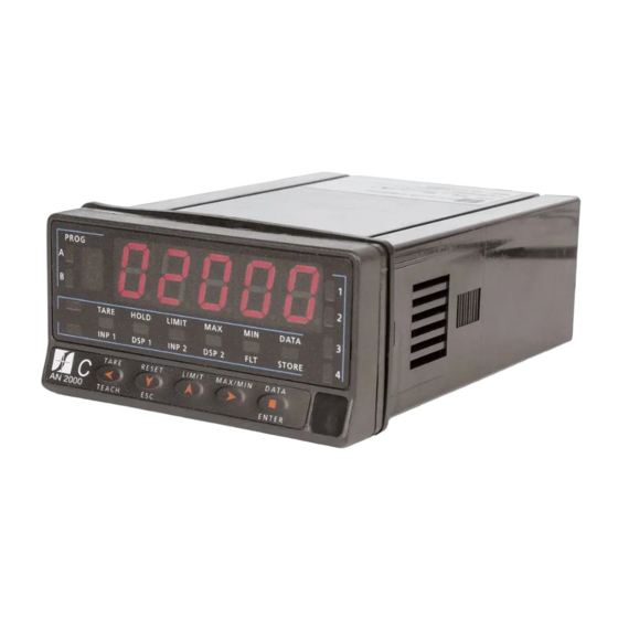
In addition, a variety of plug-in output cards can be installed at indication and control needs. any time to meet further system requirements: The model AN 2000 C of the AN series is a digital indicator designed to measure forces (weight, load, torque, pressure ...) COMMUNICATION... - Page 6 Instruction Manual Magtrol AN 2000 C FRONT-PANEL FUNCTIONS IN RUN MODE MAIN DISPLAY Reads the input variable AUXILIARY DISPLAY Positive " " or negative "-" signal LED 1 PROG Indicates activation/display setpoint 1 LED 2 RUN LED Indicates activation/display setpoint 2...
- Page 7 Magtrol AN 2000 C Instruction Manual FRONT-PANEL FUNCTIONS IN PROG MODE MAIN DISPLAY AUXILIARY DISPLAY Reads programming parameters Indicates program module FLT LED PROG Indicates input filter programming A and B LED's Indicates program module letter STORE LED Indicates exit from the program...
-
Page 8: Getting Started
Instruction Manual Magtrol AN 2000 C 2. GETTING STARTED PACKAGE CONTENTS Programming instructions (page 11 and 12) The software is divided into several independently Instructions manual in English. accessible modules to configure the input, the display, the D.P.M. model AN 2000 C. - Page 9 Magtrol AN 2000 C Instruction Manual 2.1 - Power supply Should any hardware modification be performed, remove the electronics from the case as shown in figure 9.1. 115/230 V AC: The instruments with 115/230 V AC power, are shipped from the factory for 230 V AC (USA market 115 V AC), see figure 9.2.
- Page 10 Instruction Manual Magtrol AN 2000 C OWER CONNECTION INSTALLATION To meet the requirements of the directive EN61010-1, where the unit is permanently connected to the mains supply it is obligatory to install a circuit breaking device easily reachable by the operator and clearly marked as the disconnect device.
- Page 11 Magtrol AN 2000 C Instruction Manual 2.2 – Programming instructions PROG Access to the programming mode When power is applied to the instrument, the display briefly illuminates all R U N T A R E HO LD LIMIT MA X...
- Page 12 Instruction Manual Magtrol AN 2000 C The programming instructions are composed by a general description and a series of step-by-step instructions to be followed sequentially. Each menu step is represented by an illustration of the display and keyboard module with indicators (display and LED's), reference [page number.
-
Page 13: Input Configuration
Magtrol AN 2000 C Instruction Manual 2.3 - Input configuration To completely configure the input of the load-cell indicator, it will be necessary to act on these two Fig. 13.1: Excitation jumper parameters: 1./ Excitation voltage selection. The indicator provides two excitation voltages to supply the transducer;... - Page 14 Instruction Manual Magtrol AN 2000 C 3./ Input programming range. The only configurable parameter is the input range. There are four available ranges; 15 mV, 30 mV, 60 mV or 300 mV which are to be chosen to match the cell sensitivity (max. output in mV). The maximum voltage applicable to the instrument is 300 mV. The built-in excitation voltage can be used to power up to 4 cells connected in parallel, with10 V excitation and up to 8 cells with5 V excitation.
-
Page 15: Display Configuration
Magtrol AN 2000 C Instruction Manual 3.2 - Display configuration After selection of the input range, it may be necessary to Fig. 15.1: Linearizing (inp7, dsp7) scale the instrument for the particular application. For many function with 6 (inp6, dsp6) segments (7 points). - Page 16 Instruction Manual Magtrol AN 2000 C 3./ Scaling the indicator. After deciding the values for INPUT and DISPLAY and the decimal point position, we are ready to enter in the display configuration module (2 CndSP) to effectively scale the meter. The scaling procedure is completed with digital filters and display rounding.
- Page 17 Magtrol AN 2000 C Instruction Manual MENU 2A - SCALING This menu allows programming the necessary parameters to determine the display range (INP1 - DSP1 - Decimal Point - INP2 - DSP2 - INP3 - DSP3 -…). As a default, these values are expected to be introduced by keyboard. To use the actual signal input...
- Page 18 Instruction Manual Magtrol AN 2000 C [18.1] Decimal point The decimal point goes in flash. Press repeatedly the key to move it to the right until desired position. If no PROG decimal point is required, it must be placed to the right side of the display. The decimal point remains in the selected position in all programming phases and the run mode.
- Page 19 Magtrol AN 2000 C Instruction Manual [19.1] Point 3 1 second flag indication for scaling point 3. PROG Multi-slope scaling sequence begins at this step. T ARE HOLD LIMIT DA TA INP 1 DSP1 INP 2 DS P2 F LT...
- Page 20 Instruction Manual Magtrol AN 2000 C [20.2] Point 4 1 second flag indication for scaling point 4. PROG NOTE: The instructions given for programming point 4 are applicable to the programming of points 5 to 30. T AR E HO LD...
- Page 21 Magtrol AN 2000 C Instruction Manual [21.2] Point 30 1 second flag indication for scaling point 30. PROG HOLD DATA LIMI DSP1 DSP2 STOR RESE LIMI MAX/MI ENTE DATA TEAC [21.2] Input 30 value The previously programmed INP30 value appears on the display, LED INP2 activated.
- Page 22 Instruction Manual Magtrol AN 2000 C MENU 2B - BALANCED FILTER The balanced filter acts as a delay on the display response to signal variations produced at the input. The effect of incrementing this filter level results in a softer response of the display to the input variations.
- Page 23 Magtrol AN 2000 C Instruction Manual MENU 2B - DAMPING FILTER The damping filter cuts off input values exceeding from the limits of a symmetrical band. This band becomes more selective as the filter level is increased. The filtering level is programmable from 0 to 9. Level 0 disables the filter.
- Page 24 Instruction Manual Magtrol AN 2000 C MENU 2AB - ROUND FILTER This menu allows selection among 4 levels of display rounding. When resolution is not critical, a rounding increment higher than 1, may help to stabilize the display. [24.1] Round filter The figure 24.1 shows the indication (round) corresponding to the round menu.
-
Page 25: Keyboard Functions
Magtrol AN 2000 C Instruction Manual 3. KEYBOARD AND REMOTE CONTROLS 3.1 - Keyboard functions The front-panel keyboard includes the following function keys: TARE, RESET, LIMIT and MAX/MIN. The functionality of each one, which is available in the "RUN" mode, is described next LIMIT . - Page 26 Instruction Manual Magtrol AN 2000 C To erase the peak and/or valley memories, press "MAX/MIN" MAX/MIN . This key calls up the peak and valley values one or two times to display the value to be reset. Press and contained in memory. The first push recalls the maximum hold down the "RESET"...
- Page 27 Magtrol AN 2000 C Instruction Manual 3.2 - Remote functions (CN2) The rear connector CN2 provides 4 user programmable optocoupled inputs that can be operated from external contacts or logic levels supplied by an electronic system. Four different functions may be then added to the functions available from the front-panel keys.
-
Page 28: Table Of Programmable Functions
Instruction Manual Magtrol AN 2000 C 3.3 - Table of programmable functions • Nº: Function number. • Function: Function name. • Description: Description and characteristics of the function. • Activation: • Falling edge: The operation is performed on a falling edge applied to the pin with respect to COMMON. - Page 29 Magtrol AN 2000 C Instruction Manual 13 to 16 : FUNCTIONS ASSOCIATED WITH THE ANALOG OUTPUT Nº Function Description Activation ANA GROSS Makes the analog output follow the gross value (measured value + tare) Low level ZERO ANA Puts the analog output to the zero state (0 V for 0-10 V, 4 mA for 4-20 mA)
- Page 30 Instruction Manual Magtrol AN 2000 C 29 to 36 : NEW FUNCTIONS Nº Function Description Activated by Deactivate Setpoints Deactivates the activity of the setpoints and leaves the outputs at still Low level Batch Adds the present value of the display to the totalizer and increments the Impulse batch counter once.
- Page 31 Magtrol AN 2000 C Instruction Manual 3.4 - Programming the logic inputs After deciding the functions for each connector pin, we are ready to enter in the logic inputs configuration module (6 LoGIn) to effectively programming the logic inputs. [31.1] Logic inputs...
- Page 32 Instruction Manual Magtrol AN 2000 C MENU 6A - PIN 1 programming This menu allows selecting the logic function for PIN 1. Available functions are represented by a number from 0 to 36. Consult tables to find the number corresponding to the desired function (pages 28 to 30). The instructions given below apply to pin function 1.
-
Page 33: Programming Lock Out. Access Levels
Magtrol AN 2000 C Instruction Manual 3.5 - Programming lock out / access levels In the RUN mode pulse the ENTER key during 3 second to accede to the lock menu (diagram). The instrument has an original lock code PROG PROG which is "0000". -
Page 34: Output Options
Instruction Manual Magtrol AN 2000 C 4. OUTPUT OPTIONS Optionally, the model AN 2000 C can incorporate one or The options are supplied with a specific instructions manual several output options for communications (this output should describing characteristics, installation, connections never be connected to the telephone lines) or control programming. - Page 35 Magtrol AN 2000 C Instruction Manual The figure shows the different locations of the plug-in output cards. Each location corresponds to a specific function: setpoints, analogical and serial outputs. The options 2RE, 4RE, 4OP and 4OPP are installed in the M5 connector.
- Page 36 Instruction Manual Magtrol AN 2000 C 4.1 New Functions Activate or deactivate relay / opto (+LED) via an order from rs232C or rs485. This function is available by introducing “3” in the first The new AN 2000 C provides improved functionality and digit of the parameter mode setpoints (3B ModE).
- Page 37 Magtrol AN 2000 C Instruction Manual The value parameter of the delay / hysteresis parameter New functions: (3AB ModE) indicates how long will the relay / opt be Command Function activated when the peak is reached. (Except in latch mode).
-
Page 38: Technical Specifications
Instruction Manual Magtrol AN 2000 C 5. TECHNICAL SPECIFICATIONS INPUT SIGNAL DISPLAY • • Configuration ......differential asymmetrical Main ...... -32000/32000, 5 digits 14 mm red • • Max Applicable voltage ......±300 mV DC Auxiliary ........1 digit 7.62 mm green •... -
Page 39: Dimensions And Mounting
Magtrol AN 2000 C Instruction Manual 5.1 - Dimensions and mounting FIXING CLIPS To install the instrument into the panel, make a SEALING GASKET 92x45 mm cut-out and insert the instrument into the panel from the front, placing the sealing gasket between this and the front bezel. - Page 40 Testing, Measurement and Control of Torque-Speed-Power • Load-Force-Weight • Tension • Displacement Magtrol SA ISO 9001: 2000 certified ISO 9001 Via Paolo Uccello 4 - 20148 Milano Tel +39 02 48 009 757 Fax +39 02 48 002 070 info@dspmindustria.it www.dspmindustria.it...
Need help?
Do you have a question about the AN Series and is the answer not in the manual?
Questions and answers