Table of Contents
Advertisement
Quick Links
Model DSP6000
Model DSP6000
Model DSP6000
Model DSP6000
Model DSP6000
High Speed P
High Speed P
High Speed P rogrammable
High Speed P
High Speed P
Dynamometer Controller
Dynamometer Controller
Dynamometer Controller
Dynamometer Controller
Dynamometer Controller
User
User 's Manual
User
's Manual
's Manual
's Manual
User
User
's Manual
rogrammable
rogrammable
rogrammable
rogrammable
Advertisement
Table of Contents

Related Manuals for Magtrol DSP6000


Summary of Contents for Magtrol DSP6000
- Page 1 Model DSP6000 Model DSP6000 Model DSP6000 Model DSP6000 Model DSP6000 High Speed P High Speed P rogrammable rogrammable High Speed P rogrammable rogrammable High Speed P High Speed P rogrammable Dynamometer Controller Dynamometer Controller Dynamometer Controller Dynamometer Controller Dynamometer Controller User User ’s Manual...
- Page 2 Hysteresis Brakes and Clutches While every precaution has been exercised in the compilation of this document, Magtrol, Inc. assumes no responsibility for errors or omissions. Additionally, no liability is assumed for any damages that may result from the use of the information contained within this publication.
-
Page 3: Safety Notes
Safety Notes Safety Notes Safety Notes 1. Make sure that all Magtrol dynamometers and electronic products are earth- grounded, to ensure personal safety and proper operation. 2. Check line voltage before operating the DSP6000. 3. Make sure that dynamometers and motors under test are equipped with... - Page 4 This page intentionally left blank.
-
Page 5: Table Of Contents
Setting Unit for Line Voltage ........................... 10 Figure 7. Cover for Voltage Selector, Fuses ....................10 Checking Your DSP6000 ..........................10 4 - THE DSP6000 AS A STAND-ALONE UNIT (LOCAL CONTROL) ..........12 Setting Desired Operating Parameters ......................12 ) ....................12... - Page 6 ............................14 XITING THE EMORY ..............................14 LEARING THE EMORY 5 - THE DSP6000 WITH A PC (REMOTE CONTROL) ................. 15 About the GPIB Interface ..........................15 Figure 8. GPIB (IEEE-488) Interface ......................15 GPIB (IEEE-488) C ....................15 NSTALLING THE...
-
Page 7: Introduction
In a computer-controlled provides digital readouts on the front panel. The environment, the DSP6000 provides the following DSP6000 is designed to work with all Magtrol load cell motor testing capabilities: dynamometers, including the following dynamometer •... -
Page 8: Specifications
Chapter 1 - Introduction Magtrol Model DSP6000 Dynamometer Controller PECIFICATIONS " 9 " 8 " 5 ° 8 ° 5 < ± ( ± ( ° / ± l r t ± s t i... -
Page 9: Front Panel
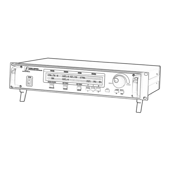
Magtrol Model DSP6000 Dynamometer Controller Chapter 1 - Introduction FRONT PANEL Figure 1. Front Panel MODEL DSP6000 DYNAMOMETER CONTROLLER The front panel provides a power switch, eight control NABLING ECONDARY UNCTIONS buttons, a Decrease/Increase Dial, and Vacuum To enable the secondary function of the double-function Fluorescent Display (VFD). -
Page 10: Front Panel Controls And Buttons
Chapter 1 - Introduction Magtrol Model DSP6000 Dynamometer Controller RONT ANEL ONTROLS AND UTTONS . s t t i n " i t n e l l a i l n i l a i l . n i . t s . -
Page 11: Vacuum Fluorescent Display (Vfd)
Refer to “DSP6000 Command Set” in Chapter 4 - The that result. Using a setting higher than necessary may DSP6000 with a PC for a list of commands recognized cause display segments to burn-in over a period of time, by the DSP6000. -
Page 12: Rear Panel
Chapter 1 - Introduction Magtrol Model DSP6000 Dynamometer Controller REAR PANEL The rear panel provides connectors and receptacles for connecting to appropriate equipment. Figure 2. Rear Panel Figure 5. Dynamometer Connector Figure 3. Brake Connector COMMON D.P. TACH. SIGNAL ISOLATED 22 VDC D.P. -
Page 13: Rear Panel Functions
Connect to Model 5241 Power Amplifier when using HD-825 CTRL OUT Dynamometer Connect accessory output cable here (optional). ACCESSORY TORQUE-SPEED OUTPUT For use with Magtrol Readouts only. Connecting another device to this output may cause equipment failure. DYNAMOMETER Connect dynamometer signal cable here AUX INPUT... -
Page 14: About The Pid Loop
If derivative is used, higher steps. gain and integral values are usually necessary. 2. Using the DSP6000 in the speed mode: Set the speed target at approximately 90% of the free-run speed. - Page 15 Chapter 2 - About the PID Loop 3. Turn the brake to the ON position and observe how The larger the I value the faster the DSP6000 will move the actual speed moves toward the target speed. to the target number, but an I value too large will cause instability (oscillation).
-
Page 16: Installation
Magtrol Dynamometer with a test motor SETTING UNIT FOR LINE VOLTAGE installed must be connected to The DSP6000 will operate with either of the following the DSP6000. It is not required power sources: that the DSP6000 be connected to a computer. - Page 17 Magtrol Model DSP6000 Dynamometer Controller Chapter 3 - Installation 7. Start the test motor. 8. Allow the motor speed to stabilize at its no-load speed for a few seconds. 9. Press the BRAKE ON/OFF button to ON. 10. Press the TORQUE SET button.
-
Page 18: The Dsp6000 As A Stand-Alone Unit (Local Control)
Alone Unit (L Alone Unit (L ocal Control) ocal Control) 4 - The DSP6000 as a Stand- 4 - The DSP6000 as a Stand-Alone Unit (L 4 - The DSP6000 as a Stand- Alone Unit (L Alone Unit (Local Control) ocal Control) ocal Control) 4. -
Page 19: Set Speed Control
Magtrol Model DSP6000 Dynamometer Controller Chapter 4 - The DSP6000 as a Stand-Alone Unit (Local Control) Desired results: 12. Use the BRAKE ON/OFF button to turn the brake • The dynamometer should load the motor under test to the load point quickly with little or no overshoot 13. -
Page 20: Setting Dynamometer Load
Chapter 4 - The DSP6000 as a Stand-Alone Unit (Local Control) Magtrol Model DSP6000 Dynamometer Controller 6. Press SHIFT. ECALLING OINTS 7. Press UP ! or DOWN " until you see the 1. Press and release RECALL. The VFD will indicate desired GPIB address. -
Page 21: The Dsp6000 With A Pc (Remote Control)
5 - The DSP6000 with a PC (Remote Control) 5 - The DSP6000 with a PC (R emote Control) emote Control) The DSP6000 can be used with a computer to control a Figure 8. GPIB (IEEE-488) Interface dynamometer and to transmit data from motor testing directly to the computer. -
Page 22: Checking The Dsp6000-To-Pc Connection
Chapter 5 - The DSP6000 with a PC (Remote Control) Magtrol Model DSP6000 Dynamometer Controller Some PC interfaces can access from one to fifteen 4-bit PROGRAMMING primary addresses. Other interfaces can access as many as thirty-one 5-bit primary addresses. The DSP6000... -
Page 23: Command Set For Dsp6000
Magtrol Model DSP6000 Dynamometer Controller Chapter 5 - The DSP6000 with a PC (Remote Control) DSP6000 OMMAND ET FOR Command Command Function Explanation Category Code Communications Sets high data acquisition The Controller outputs data at 120 S/s (Using an rate (120 samples per RS-232 interface, the rate is 60 S/s.) Use this... - Page 24 Chapter 5 - The DSP6000 with a PC (Remote Control) Magtrol Model DSP6000 Dynamometer Controller Command Command Function Explanation Category Code Setup Resets as follows: Use this command to cancel any previous • Manual control ON commands. • Low data acquisition rate Note: These settings are the power-on default •...
- Page 25 Magtrol Model DSP6000 Dynamometer Controller Chapter 5 - The DSP6000 with a PC (Remote Control) Command Command Function Explanation Category Code Speed Sets maximum speed to Commands A, B, C, D, E and F# set a speed 16,000 RPM range for the Controller. One of these commands...
-
Page 26: Acquiring Speed-Torque Data
Chapter 5 - The DSP6000 with a PC (Remote Control) Magtrol Model DSP6000 Dynamometer Controller ACQUIRING SPEED-TORQUE DATA Figure 9. Connector Pin-Out Speed-torque data is a fixed-length string in ASCII format with a floating point decimal. Use the following string format: SdddddTdddd.R[cr][lf]... -
Page 27: Calibration
Offset and Gain are stored in nonvolatile 2. Turn on the DSP6000. memory. They remain in effect until the user or the 3. Allow the DSP6000 to warm up for at least 30 calibration house updates them. minutes. -
Page 28: Accessory Torque Offset And Gain
ALIBRATION ROCEDURE 9. Repeat steps 3 through 8 to complete this procedure. The DSP6000 can also be calibrated by using a certified 10. Record the correction factors displayed above the dynamometer, calibration beam, and weight instead of ZERO and GAIN readouts for future reference. -
Page 29: Figure 10. Alternative Calibration
Magtrol Model DSP6000 Dynamometer Controller Chapter 6 - Calibration 8. Remove the weight for ZERO adjustment. Figure 10. Alternative Calibration 9. Press the ZERO button. Torque = Weight (W) x Distance (D) 10. Adjust the Increase/Decrease Dial until the display Weight (W) = Torque / Distance (D) indicates 0 mVDC. -
Page 30: Troubleshooting
OFF. applied with no shaft rotation. in use (if possible). Reduce output current to 0. If you require additional assistance, please contact Magtrol Customer Service at 1-800-828-7844 or 1-716-668-5555... -
Page 31: Appendix A: Labview® Programming Examples
: LabVIEW abVIEW abVIEW rogramming Examples rogramming Examples ® ® ® ® ® Magtrol offers a comprehensive motor-test software program to satisfy most of your programming needs. To order your software, call Magtrol Sales at 1-800-828-7844 or 1-716-668-5555. SIMPLE READ... -
Page 32: Torque Stabilized
Appendix A: LabVIEW Programming Examples Magtrol Model DSP6000 Dynamometer Controller TORQUE STABILIZED... -
Page 33: Speed Stabilized
Magtrol Model DSP6000 Dynamometer Controller Appendix A: LabVIEW Programming Examples SPEED STABILIZED... -
Page 34: Appendix B: Inertia Correction
When DATA the speed stabilizes, use this as the static torque A major advantage of the DSP6000 is its ability to obtain value. full motor performance data (free run to locked rotor) -
Page 35: Appendix C: Front Panel/Display Menu Flow Charts
Appendix C Appendix C ront P ront P anel/Display Menu Flow Charts anel/Display Menu Flow Charts Appendix C Appendix C: F Appendix C : Front P ront P ront Panel/Display Menu Flow Charts anel/Display Menu Flow Charts anel/Display Menu Flow Charts DYNO SETUP MENU 6000 bit 600 bit... -
Page 36: Com Setup Menu
Appendix C: Front Panel/Display Menu Flow Charts Magtrol Model DSP6000 Dynamometer Controller COM SETUP MENU 19200 9600 4800 RS-232 2400 BAUD: 1200 GPIB 0 - 15 COM SETUP: ADDRESS: 0 - 3 CONTRAST:... -
Page 37: Aux Setup Menu
Magtrol Model DSP6000 Dynamometer Controller Appendix C: Front Panel/Display Menu Flow Charts AUX SETUP MENU 0 - 10000 SCALE: UNITS/VOLT AUX SETUP: DISPLAY: POWER UNITS MENU POWER UNITS:... -
Page 38: Torque Units Menu
Appendix C: Front Panel/Display Menu Flow Charts Magtrol Model DSP6000 Dynamometer Controller TORQUE UNITS MENU N.cm N.mm kg.cm TORQUE g.cm UNITS: lb.ft. lb.in. oz.ft. oz.in. -
Page 39: Appendix D: Schematics
Appendix D Appendix D : Schematics : Schematics Appendix D Appendix D Appendix D: Schematics : Schematics : Schematics ENCODER/SWITCH BOARD (PB0) (PB1) (PB2) (PB3) (PB4) (PB5) (PB6) (PB7) (PB8) (PB9) (ROTARY ENCODER) (PB10) SW10 (AUDIO) (+ 5V) SPKR1 (GND) POWER SUPPLY +5VD +5VA... -
Page 40: Dsp & Memory
Appendix D: Schematics Magtrol Model DSP6000 Dynamometer Controller DSP & MEMORY... -
Page 41: Analog I/O
Magtrol Model DSP6000 Dynamometer Controller Appendix D: Schematics ANALOG I/O... -
Page 42: Glossary Of Abbreviations And Terms
Glossar Glossar y of Abbreviations and T y of Abbreviations and T erms erms Glossar Glossar y of Abbreviations and T Glossar y of Abbreviations and T y of Abbreviations and Terms erms erms BNC ................bayonet, locking-type connector CCW ................counterclockwise (turn to left) CF ................ -
Page 43: Magtrol Limited Warranty
If purchaser fails to give notice, the delivery shall be deemed to conform with the terms of the order. The purchaser assumes all risk of loss or damage to products upon delivery by Magtrol to the carrier. If a product is damaged in transit, PURCHASER MUST FILE ALL CLAIMS FOR DAMAGE WITH THE CARRIER to obtain compensation. - Page 44 70 Gardenville Parkway ! Buffalo, New York 14224 Phone: (716) 668-5555 ! (800) 828-7844 Fax: (716) 668-8705 Web site: www.magtrol.com ! E-mail: magtrol@magtrol.com MOTOR TESTING EQUIPMENT ! HYSTERESIS BRAKES AND CLUTCHES...
Need help?
Do you have a question about the DSP6000 and is the answer not in the manual?
Questions and answers