
Subscribe to Our Youtube Channel
Related Manuals for Magtrol DSP6001


Summary of Contents for Magtrol DSP6001
- Page 1 Model DSP6001 High Speed Programmable Dynamometer Controller User’s Manual Via Paolo Uccello 4 - 20148 Milano Tel +39 02 48 009 757 Fax +39 02 48 002 070 info@dspmindustria.it www.dspmindustria.it...
- Page 2 While every precaution has been exercised in the compilation of this document to ensure the accuracy of its contents, Magtrol, Inc. assumes no responsibility for errors or omissions. Additionally, no liability is assumed for any damages that may result from the use of the information contained within this publication.
-
Page 3: Safety Precautions
Safety Precautions 1. Make sure that all Magtrol dynamometers and electronic products are earth-grounded, to ensure personal safety and proper operation. 2. Check line voltage before operating the DSP6001. 3. Make sure that dynamometers and motors under test are equipped with appropriate safety... -
Page 4: Revisions To This Manual
1st Edition - rev. H Changed M-TEST 4.0 references to “M-TEST” or “M-TEST 5.0” throughout manual 06/28/04 1st Edition - rev. G Removed DSP6001 resetting procedure 05/24/04 1st Edition - rev. F Added DIR#, OH1 and IOXX.XX Misc. Command codes 8.6.7, D.6... -
Page 5: Table Of Contents
MANUAL ORGANIZATION .............................IX CONVENTIONS USED IN THIS MANUAL ........................X 1. INTRODUCTION ..........................1 1.1 UNPACKING YOUR DSP6001 ............................. 1 1.2 NEW FEATURES OF THE DSP6001 ........................... 1 1.3 DATA SHEET ................................. 2 2. CONTROLS ............................8 2.1 FRONT PANEL ................................8 2.2 FRONT PANEL CONTROLS AND BUTTONS ...................... -
Page 6: Table Of Contents
Table of Contents Magtrol Model DSP6001 Dynamometer Controller 3.3 SPEED ENCODER SETUP ............................36 3.3.1 Bit Configurations ............................36 3.4 TORQUE/SPEED ANALOG OUTPUTS ........................37 3.4.1 Torque DAC Scale Factor ..........................37 3.4.2 Speed DAC Scale Factor ..........................37 3.4.3 Torque/Speed DAC Setup .......................... - Page 7 8.2.1 Connection ..............................66 8.2.2 Communication Parameters ........................... 67 8.2.3 Baud Rate ............................... 67 8.3 CHECKING THE DSP6001-TO-PC CONNECTION ....................67 8.4 DATA FORMAT ................................68 8.5 PROGRAMMING ............................... 68 8.5.1 Data Termination Characters .......................... 68 8.5.2 Timeout ................................69 8.6 DSP6001 COMMAND SET ............................
- Page 8 Table of Contents Magtrol Model DSP6001 Dynamometer Controller 9.3.2 TSC1 Offset and Gain ............................ 77 9.3.3 TSC2 Offset and Gain ............................ 78 9.3.4 DAC Output Offset and Gain ......................... 78 9.3.5 Speed Check ..............................80 9.3.6 Decimal Point Check............................81 10.
-
Page 9: Table Of Figures
Magtrol Model DSP6001 Dynamometer Controller Table of Contents TABLE OF FIGURES 2. CONTROLS Figure 2–1 Front Panel ..............................8 Figure 2–2 Secondary Function Menu ........................8 Figure 2–3 Saving Function Menu ..........................9 Figure 2–4 Rear Panel ..............................12 Figure 2–5 Dynamometer Brake Input ........................12 Figure 2–6 Accessory Torque-Speed Output ......................12... - Page 10 Table of Contents Magtrol Model DSP6001 Dynamometer Controller Figure 5–4 High Initial P Setting for Torque Control .....................44 Figure 5–5 Initial I Setting for Torque Control ......................45 Figure 5–6 Initial D Setting for Torque Control .......................45 Figure 5–7 Initial P Setting for Speed Control at 25% ....................46 Figure 5–8 Initial I Setting for Speed Control ......................47...
-
Page 11: Preface
WHO SHOULD USE THIS MANUAL This manual is intended for bench test operators who are going to use the Model DSP6001 Dynamometer Controller in conjunction with any Magtrol Hysteresis, Eddy-Current or Powder Brake Dynamometer, Magtrol In-Line Torque Transducer or auxiliary instrumentation. -
Page 12: Conventions Used In This Manual
TROUBLESHOOTING - Solutions to common problems encountered during setup and testing. Appendix A: LABVIEW™ PROGRAMMING EXAMPLES - Magtrol’s comprehensive motor-test software programs, made specifically to compliment the DSP6001 Dynamometer Controller. Appendix B: INERTIA CORRECTION - Describes the inertial effect on motor test data providing solutions for correction. -
Page 13: Introduction
Introduction UNPACKING YOUR DSP6001 Your DSP6001 was packaged carefully for shipping. Please notify your carrier and Magtrol Customer Service if you believe your unit was damaged in shipping. 1. Save all shipping cartons and packaging material until you inspect the DSP6001. -
Page 14: Data Sheet
PC control via the IEEE-488 or RS-232 points per second via IEEE bus (approx. 60/sec. via interface. With 120 readings per second, the DSP6001 is ideally RS-232) suited for both the test lab and the production line. - Page 15 Magtrol Model DSP6001 Dynamometer Controller Chapter 1 – Introduction Specifications DSP6001 MEASUREMENT CHARACTERISTICS DIMENSIONS Maximum Torque 10,000 units, ±5 V TSC1, ±10 V TSC2 Width 19.0 in 483 mm Maximum Speed 99,999 rpm Height 3.5 in 89 mm Speed: 0.01% of reading from 10 rpm to 100,000 rpm Depth 12.4 in...
- Page 16 FUSE (5×20mm): IEC 1A 250V T 240V IEC 315mA 250V T M-TEST Hysteresis on TSC1 only DSP6001 Connected to Hysteresis Dynamometer with Optional Auxiliary Input or In-Line Torque Transducer Hysteresis Dynamometer (HD) Eddy-Current (WB) OR Powder Brake (PB) Dynamometer Motor...
- Page 17 MAGTROL, INC. BUFFALO, NY FUSE (5×20mm): IEC 1A 250V T 240V IEC 315mA 250V T DSP6001 DYNAMOMETER CONTROLLER DSP6001 Connected to 2 Eddy-Current or 2 Powder Brake Dynamometers (Tandem Setup) Powder Brake Eddy-Current Brake Dynamometer (PB) Dynamometer (WB) Clutch (EK)
- Page 18 DES 31x In-Line Torque Transducer Cross Loop Function CUSTOM MOTOR TEST SYSTEM The DSP6001 can be incorporated into a Customized Motor Test System. These PC based, turn-key systems are custom designed and built to meet specific user requirements. heavy-duty equipment rack...
- Page 19 DES 310 Power Supply for WB & PB Dynamometer series 65, 115 and 15 DES 311 Torque/Speed Conditioner TSC 401 MISC. (required for connecting WB/PB Series Dynamometers to DSP6001) GPIB Interface Card (PCI) 73-M023 GPIB Cable, 1 meter 88M047 CARDS &...
-
Page 20: Controls
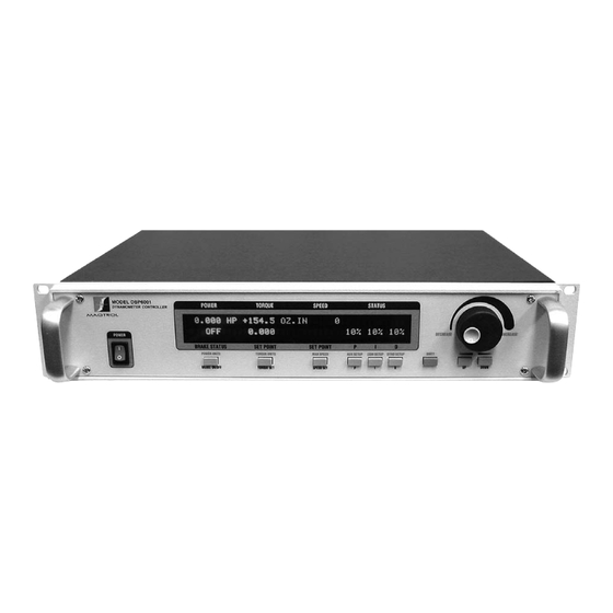
2. Controls FRONT PANEL The front panel provides a power switch, nine control buttons, a Decrease/Increase Dial, and Vacuum Fluorescent Display (VFD). MODEL DSP6001 POWER TORQUE SPEED STATUS DYNAMOMETER CONTROLLER DECREASE INCREASE POWER BRAKE STATUS SET POINT SET POINT POWER UNITS... -
Page 21: Enabling Saving Function
Magtrol Model DSP6001 Dynamometer Controller Chapter 2 – Controls 2. Press any control button to enable the function shown in blue letters above the button. 3. Press the SHIFT button again to exit the secondary function and return to main menu. -
Page 22: Vacuum Fluorescent Display (Vfd)
Chapter 2 – Controls Magtrol Model DSP6001 Dynamometer Controller 2.2.3.2 Double-Function Buttons Button To Use Function POWER UNITS Press SHIFT and release; then Sets desired unit of power. Press press this button. UP or DOWN button to see options. -
Page 23: Contrast Settings
In order to help eliminate the possibility of display damage, a Screen Saver has been programmed into the DSP6001. If the display has been turned on for more than 5 minutes without any activity, a Screen Saver with moving arrows will appear. -
Page 24: Rear Panel
Chapter 2 – Controls Magtrol Model DSP6001 Dynamometer Controller REAR PANEL The rear panel provides connectors and receptacles for connecting to appropriate equipment. CAUTION: DOUBLE POLE FUSING 75VA 50/60Hz AUX / TSC2 BRAKE SUPPLY 2 ACCESSORY TORQUE–SPEED... -
Page 25: Figure 2-7 Dynamometer/Tsc1 Connector
Magtrol Model DSP6001 Dynamometer Controller Chapter 2 – Controls DYNAMOMETER/ Connect dynamometer signal cable here. TSC1 1. FLOW/CLUTCH 8. +5.0 VDC COM 2. TACH. B 9. D.P. A 3. +24 VDC 10. TACH. A 4. +24 VDC COM 11. INDEX 5. -
Page 26: Figure 2-10 Supply 2 Connector
Chapter 2 – Controls Magtrol Model DSP6001 Dynamometer Controller SUPPLY 2 Connect WB/PB DES supply for TSC2. 14 13 12 11 10 1. SHIELD (EARTH) 2. ELECTRICAL ALARM CHANNEL 2 3. CLUTCH 4. PRIMARY SUPPLY CONTR. CHANNEL 2 5. SUPPLY +24 VDC 6. -
Page 27: Installation/Configuration
STARTING! 3.1.1 etting nit for oLtage The DSP6001 will operate with either of the following power sources: • 120 V 50/60 Hz • 240 V 50/60 Hz 1. Find the line cord receptacle on rear panel. The line cord is a detachable NEMA Standard 3 wire. -
Page 28: Self-Test
Chapter 3 – Installation/Configuration Magtrol Model DSP6001 Dynamometer Controller 3.1.2 After turning the power on to the DSP6001, the display panel will show all segments of the VFD (series of rectangles), indicating that the DSP6001 is downloading the program. POWER... -
Page 29: Testing Instrumentation Setup
Magtrol Model DSP6001 Dynamometer Controller Chapter 3 – Installation/Configuration TESTING INSTRUMENTATION SETUP The DSP6001 has the ability to support a combination of up to two testing instruments with independent or tandem configurations. Typically used combinations include: TSC1 TSC2 HD = Hysteresis Dynamometer... -
Page 30: Dynamometer Configuration Menu
To reach the dynamometer configuration menu: 1. Turn on DSP6001 power. See Section 3.1 – Powering Up the DSP6001. 2. Press SHIFT. The word “SHIFT” will appear in the display. 3. Press the DYNO SETUP button. The display should appear as follows:... -
Page 31: Hysteresis Dynamometer Setup
Figure 3–8 Hysteresis Dynamometer Setup 3.2.2.2 Software Configuration 1. Turn on the DSP6001 and proceed to the dynamometer configuration menu. See Section 3.2.1 – Dynamometer Configuration Menu. 2. Select TSC1 until HD is reached. 3. Select TSC2 until AUX is reached. -
Page 32: Hysteresis Dynamometer With Torque Transducer Setup
Chapter 3 – Installation/Configuration Magtrol Model DSP6001 Dynamometer Controller 3.2.3 yStereSiS ynaMoMeter witH orqUe ranSDUCer etUp 3.2.3.1 Hardware Connection Hysteresis Dynamometer (HD) TM Torque Transducer Motor Under Test AC Mains GPIB DSP6001 DYNAMOMETER No Connection RS-232 CONTROLLER CAUTION: DOUBLE POLE FUSING... -
Page 33: Figure 3-11 Torque Transducer Setup Menu
Chapter 3 – Installation/Configuration 3.2.3.2 Software Configuration 1. Turn on the DSP6001 and proceed to the dynamometer configuration menu. See Section 3.2.1 – Dynamometer Configuration Menu. 2. Select TSC1 until HD is reached. 3. Select TSC2 until TM2XX is reached. -
Page 34: Hysteresis Dynamometer With Auxiliary Instrumentation Setup
Chapter 3 – Installation/Configuration Magtrol Model DSP6001 Dynamometer Controller 3.2.4 yStereSiS ynaMoMeter witH UxiLiary nStrUMentation etUp 3.2.4.1 Hardware Connection Hysteresis Dynamometer (HD) Motor Auxiliary Input (optional) Under ±10 volts Test TSC2 only 14-pin connector AC Mains pin 13 = com... -
Page 35: Figure 3-15 Tsc2 Aux Setup Menu
Chapter 3 – Installation/Configuration 3.2.4.2 Software Configuration 1. Turn on the DSP6001 and proceed to the dynamometer configuration menu. See Section 3.2.1 – Dynamometer Configuration Menu. 2. Select TSC1 until HD is reached. 3. Select TSC2 until AUX is reached. -
Page 36: Hysteresis Dynamometer With Eddy-Current Or Powder Brake Setup
Chapter 3 – Installation/Configuration Magtrol Model DSP6001 Dynamometer Controller 3.2.5 yStereSiS ynaMoMeter witH Urrent or owDer rake etUp 3.2.5.1 Hardware Connection Hysteresis Dynamometer (HD) Eddy-Current (WB) OR Powder Brake (PB) Dynamometer Motor Under Test TSC 401 Torque-Speed AC Mains Conditioner... -
Page 37: Figure 3-18 Tsc2 Eddy-Current/Powder Brake Setup Menu
Chapter 3 – Installation/Configuration 3.2.5.2 Software Configuration 1. Turn on the DSP6001 and proceed to the dynamometer configuration menu. See Section 3.2.1 – Dynamometer Configuration Menu. 2. Select TSC1 until HD is reached. 3. Select TSC2 until WB or PB is reached. -
Page 38: Eddy-Current Or Powder Brake Dynamometer Setup
Figure 3–20 Eddy-Current or Powder Brake Dynamometer Setup 3.2.6.2 Software Configuration 1. Turn on the DSP6001 and proceed to the dynamometer configuration menu. See Section 3.2.1 – Dynamometer Configuration Menu. 2. Select TSC1 until WB or PB is reached. 3. Select TSC2 until AUX is reached. -
Page 39: Eddy-Current Or Powder Brake Dynamometer With Torque Transducer Setup
Figure 3–22 Eddy-Current or Powder Brake Dynamometer with Torque Transducer Setup 3.2.7.2 Software Configuration 1. Turn on the DSP6001 and proceed to the dynamometer configuration menu. See Section 3.2.1 – Dynamometer Configuration Menu. 2. Select TSC1 until WB or PB is reached. -
Page 40: Eddy-Current Or Powder Brake Dynamometer With Auxiliary Instrumentation Setup
Figure 3–23 Eddy-Current or Powder Brake Dynamometer with Auxiliary Instrumentation Setup 3.2.8.2 Software Configuration 1. Turn on the DSP6001 and proceed to the dynamometer configuration menu. See Section 3.2.1 – Dynamometer Configuration Menu. 2. Select TSC1 until WB or PB is reached. -
Page 41: Two Eddy-Current/Powder Brake Dynamometers (Independent Setup)
Magtrol Model DSP6001 Dynamometer Controller Chapter 3 – Installation/Configuration 3.2.9 Urrent owDer rake ynaMoMeterS nDepenDent etUp 3.2.9.1 Hardware Connection Eddy-Current (WB) Eddy-Current (WB) OR Powder Brake (PB) OR Powder Brake (PB) Dynamometer Dynamometer TSC 401 Torque-Speed TSC 401 Torque-Speed Conditioner... -
Page 42: Figure 3-25 Tandem Configuration Menu
Magtrol Model DSP6001 Dynamometer Controller 3.2.9.2 Software Configuration 1. Turn on the DSP6001 and proceed to the dynamometer configuration menu. See Section 3.2.1 – Dynamometer Configuration Menu. 2. Select TSC1 until WB or PB is reached. 3. Select TSC2 until WB or PB is reached. -
Page 43: Two Eddy-Current/Powder Brake Dynamometers (Tandem Setup)
Magtrol Model DSP6001 Dynamometer Controller Chapter 3 – Installation/Configuration 3.2.10 Urrent owDer rake ynaMoMeterS anDeM etUp 3.2.10.1 Hardware Connection Eddy-Current (WB) Eddy-Current (WB) Dynamometer Dynamometer Powder Brake (PB) Powder Brake (PB) Dynamometer Dynamometer TSC 401 TSC 401 Torque-Speed Conditioner Torque-Speed Conditioner... - Page 44 Magtrol Model DSP6001 Dynamometer Controller 3.2.10.2 Software Configuration 1. Turn on the DSP6001 and proceed to the dynamometer configuration menu. See Section 3.2.1 – Dynamometer Configuration Menu. 2. Select TSC1 until WB or PB is reached. 3. Select TSC2 until WB or PB is reached.
-
Page 45: Eddy-Current Dynamometer With Powder Brake Dynamometer (Tandem Setup)
Figure 3–27 Eddy-Current Dynamometer with Powder Brake Dynamometer (Tandem Setup) 3.2.11.2 Software Configuration 1. Turn on the DSP6001 and proceed to the dynamometer configuration menu. See Section 3.2.1 – Dynamometer Configuration Menu. 2. Select TSC1 until WB is reached. 3. Select TSC2 until PB is reached. -
Page 46: Figure 3-29 Tsc2 Powder Brake Setup Menu
Chapter 3 – Installation/Configuration Magtrol Model DSP6001 Dynamometer Controller 8. Press SHIFT 2 times to get to the TSC2 Powder Brake Setup Menu as shown below. POWER TORQUE SPEED STATUS BRAKE STATUS SET POINT SET POINT Figure 3–29 TSC2 Powder Brake Setup Menu 9. -
Page 47: In-Line Torque Transducer Cross Loop Function
Torque Transducer. 3.2.12.2 Software Configuration 1. Turn on the DSP6001 and proceed to the dynamometer configuration menu. See Section 3.2.1 – Dynamometer Configuration Menu. 2. Select TSC1 until BRAKE is reached. 3. Select TSC2 until TM2XX is reached. -
Page 48: Speed Encoder Setup
Chapter 3 – Installation/Configuration Magtrol Model DSP6001 Dynamometer Controller 8.a. If choosing a Hysteresis or Powder Brake Type, press SHIFT 2 times to complete setup and return to main menu. 8.b. If choosing an Eddy-Current Brake Type, menu will appear as follows:... -
Page 49: Torque/Speed Analog Outputs
Magtrol Model DSP6001 Dynamometer Controller Chapter 3 – Installation/Configuration TORQUE/SPEED ANALOG OUTPUTS Torque and Speed DAC Outputs provide an analog output proportional to the torque and speed of the system. They are available on the Accessory Torque-Speed Output Connector (as seen in Figure 2–6 Accessory Torque-Speed Output) and are updated every 2 milliseconds. -
Page 50: Digital Filters
FILTER PARAMETERS The input to the A/D converter internal to the DSP6001 has a traditional analog filter that is comprised of the following characteristics: •... -
Page 51: Filter Setup
Magtrol Model DSP6001 Dynamometer Controller Chapter 4 – Digital Filters FILTER SETUP Note: Filter setup should take place after hardware installation and software configuration of the chosen testing instruments has been completed. See Chapter 3 – Installation/Configuration. There are four different Filter settings to choose from including 10 Hz, 25 Hz, 50 Hz and OFF. The following instructions show how to select the desired Filter for each channel: 1. -
Page 52: Pid Settings
5. PID Settings ABOUT THE PID LOOP The DSP6001 has PID adjustment capability for both the speed and torque modes to provide the best system response. The PID Loop comprises the following three variables: proportional gain integral derivative Other important variables include: •... -
Page 53: How The Pid Loop Works
Magtrol Model DSP6001 Dynamometer Controller Chapter 5 – PID Settings HOW THE PID LOOP WORKS The following diagram demonstrates the correlation between the variables in the PID LoOp. e(t) Yd(t) Yp(t) Yt(t) Ys(t) Set Point Derivative Proportional Scale HD & PB... -
Page 54: Equations
Chapter 5 – PID Settings Magtrol Model DSP6001 Dynamometer Controller 5.3.3 qUationS Where Skp, Ski and Skd are system coefficients… Yd(t) = (e(t) - e(t-3) + 3 * (e(t-1) - e(t-2))) * (10/Skd) * D% Yp(t) = (e(t) + Yd(t)) * (10/Skp) * P%... -
Page 55: Setting The Correct Pid's For Your Motor
Magtrol Model DSP6001 Dynamometer Controller Chapter 5 – PID Settings 5.4.1.3 Setting Additional Scale Factor for D (Derivative) 1. Starting from the main menu, press and hold the D button. While holding the D button, press SHIFT. 2. Use the D button to toggle through the letters in the unit (A, B, C, D, E, F, G, H and I). -
Page 56: Figure 5-3 Initial P Setting For Torque Control At 25
Chapter 5 – PID Settings Magtrol Model DSP6001 Dynamometer Controller Figure 5–3 Initial P Setting for Torque Control at 25% Figure 5–4 High Initial P Setting for Torque Control 6. Turn the brake OFF. 7. Increase the I term to 10%. -
Page 57: Figure 5–5 Initial I Setting For Torque Control
Magtrol Model DSP6001 Dynamometer Controller Chapter 5 – PID Settings a. If the response was too slow, increase the I term in 1-5% increments and repeat #8. b. If the response was too fast, decrease the I term in 1-5% increments and repeat #8. -
Page 58: Setting The Pid For Speed Control
Chapter 5 – PID Settings Magtrol Model DSP6001 Dynamometer Controller 5.5.3 etting tHe peeD ontroL 1. With the motor and brake OFF, set the desired Speed Set Point by pressing the SPEED SET button and using the UP and DOWN buttons and Decrease/Increase dial. -
Page 59: Figure 5–8 Initial I Setting For Speed Control
Magtrol Model DSP6001 Dynamometer Controller Chapter 5 – PID Settings Figure 5–8 Initial I Setting for Speed Control c. If there is too much over shoot, increase the D term in 1% increments and repeat #8. For each incremental increase of the D term, reduce the P term by a proportional amount. -
Page 60: Setting The Pid For Ramp Down
Magtrol’s M-TEST Software provides a setup PID function in the setup for the ramp test. In the M-TEST Software, the dynamic scaling can be enabled or disabled and the span of the scaling can also be selected. -
Page 61: Figure 5–11 Ramp Down High I
Magtrol Model DSP6001 Dynamometer Controller Chapter 5 – PID Settings Figure 5–11 Ramp Down High I Ramp shows higher value for I term. Note “bump” at beginning of ramp has been reduced but there are poor results toward end of ramp. -
Page 62: Alar M System
6. Alar m System GENERAL INFORMATION New to the DSP6001 is a built-in alarm system, designed to caution the user when problems occur. An automatic electrical and temperature alarm is programmed into the unit to protect against electrical overloads and overheating equipment when using a Magtrol DES 3XX Power Supply. There are also power, speed, torque, air flow, water flow and external input alarms internal to the unit, which only become active when enabled by the user. -
Page 63: Alarm Operation
LarM peration The DSP6001 gives the user the ability to enable or disable the alarms in the unit. The default is set in the OFF position. In order for the alarms to be operative the user must enable them. 6.1.2.1 How to Enable/Disable Alarms 1. -
Page 64: Alarm Priority
Chapter 6 – Alarm System Magtrol Model DSP6001 Dynamometer Controller 6.1.3 LarM riority While in an alarm condition, a higher priority alarm will be acknowledged, while lower priority alarms are ignored. The priority order is as follows. Availability Priority Alarm... -
Page 65: Power Alarm Action
Magtrol Model DSP6001 Dynamometer Controller Chapter 6 – Alarm System 6.2.2 ower LarM Ction When the power exceeds that of the maximum power setting, the message -OL- will appear and blink in the power section of the display accompanied by an audible beeping sound (as indicated in Figure 6–6). -
Page 66: Maximum Speed Alarm Action
Chapter 6 – Alarm System Magtrol Model DSP6001 Dynamometer Controller 6.3.2 axiMUM peeD LarM Ction A. If speed is greater than the maximum speed setting but less than 120%, -OL- will flash on the display where the speed reading was (as indicated in Figure 6–8) and will be accompanied by an audible beeping sound. -
Page 67: Maximum Torque Alarm Action
Magtrol Model DSP6001 Dynamometer Controller Chapter 6 – Alarm System POWER TORQUE SPEED STATUS BRAKE STATUS SET POINT SET POINT Figure 6–10 Torque Alarm Setup Menu 5. Press AUX SETUP button and use UP and DOWN buttons and Decrease/Increase dial to set desired maximum torque for TSC1. -
Page 68: Air Flow Alarm
Chapter 6 – Alarm System Magtrol Model DSP6001 Dynamometer Controller AIR FLOW ALARM • Used to indicate a lack of air flow from a blower or air line • Only for use with Hysteresis Dynamometers • Monitored only when the brake is ON •... -
Page 69: Water Flow Alarm
Magtrol Model DSP6001 Dynamometer Controller Chapter 6 – Alarm System WATER FLOW ALARM • Used to indicate lack of water flow • Only for use with Eddy-Current or Powder Brake Dynamometers • Default is set in “OFF” mode • Monitored only when the brake is “ON”... -
Page 70: External Alarm
Chapter 6 – Alarm System Magtrol Model DSP6001 Dynamometer Controller EXTERNAL ALARM • Used to shut down system based on additional user input • Default is set in “OFF” mode 6.7.1 nStrUCtionS for xternaL LarM etUp 1. Starting from main menu, press SHIFT. -
Page 71: Temperature Alarm
Magtrol Model DSP6001 Dynamometer Controller Chapter 6 – Alarm System TEMPERATURE ALARM • To alert user when dynamometer gets too hot and thermal switch opens • Only available for use with WB or PB dynamometers • Default - always active 6.8.1... -
Page 72: Electrical Alarm
Chapter 6 – Alarm System Magtrol Model DSP6001 Dynamometer Controller ELECTRICAL ALARM • Used to protect the DES supply • Monitors electrical input (mains) and circuitry of the DES • Only available for use with WB or PB dynamometers •... -
Page 73: Manually Controlled Operation
All steps that are completed will be saved within that channel until the information is manually changed or the DSP6001 is reset. (To reset the DSP6001, refer to Section 9.4 – Resetting the DSP6001.) Note:... -
Page 74: How To Set Desired Power Units
Chapter 7 – Manually Controlled Operation Magtrol Model DSP6001 Dynamometer Controller HOW TO SET DESIRED POWER UNITS To select the desired power units (W, kW or HP): 1. Press SHIFT. 2. Press POWER UNITS button. The display should appear as follows:... -
Page 75: How To Set Speed Control
Magtrol Model DSP6001 Dynamometer Controller Chapter 7 – Manually Controlled Operation Note: PID values should be set at this time. See Section 5.5 – Setting the Correct PID’s for Your Motor. 3. Use the BRAKE ON/OFF button to turn the brake ON. -
Page 76: How To Set Open Loop Control
Chapter 7 – Manually Controlled Operation Magtrol Model DSP6001 Dynamometer Controller 4. Press the SHIFT button to exit the MAX SPEED function. 5. Press the SPEED SET button. 6. Use UP and DOWN buttons and the Decrease/Increase dial to set a speed equal to the max. -
Page 77: Computer Controlled Operation
8. Computer Controlled Operation The DSP6001 can be used with a computer to control a dynamometer and to transmit data from the motor testing device directly to the computer. Using the DSP6001 with a computer enables the unit to perform at its full capacity. -
Page 78: Changing The Gpib Primary Address
Each instrument serviced by the GPIB has its own Primary Address code, which enables the computer to obtain readings from the instrument. The factory default of the setting on the DSP6001 is 09. Some PC interfaces can access from one to fifteen 4-bit primary addresses. Other interfaces can access as many as thirty-one 5-bit primary addresses. -
Page 79: Communication Parameters
Make sure that the DSP6001 and its host computer are communicating before acquiring data. 1. Make sure the primary GPIB address is set correctly for the DSP6001. 2. Set the input variable to 15 characters (13 variable characters and the two required data termination characters CR and LF. -
Page 80: Data Format
Use the following information to answer the formatting questions asked when installing your GPIB software. All GPIB data acquisition systems require the use of data termination characters. The DSP6001 uses the GPIB standard termination characters Carriage Return (CR) and Line Feed (LF). Provide them in that order. -
Page 81: Timeout
Magtrol Model DSP6001 Dynamometer Controller Chapter 8 – Computer Controlled Operation 8.5.1.2 Codes for CR - LF BASIC CR = CHR$(13) LF = CHR$(10) 8.5.2 iMeoUt Set the timeout for at least one second if asked to set a communication fault delay timeout. -
Page 82: Communication Commands
Chapter 8 – Computer Controlled Operation Magtrol Model DSP6001 Dynamometer Controller 8.6.2 oMMUniCation oMManDS Command Function Explanation Code *IDN? Returns Magtrol Identification and software revision. Prompts to return to auxiliary Output Auxiliary prompt to return the value at input data string. -
Page 83: Ramp Commands
Magtrol Model DSP6001 Dynamometer Controller Chapter 8 – Computer Controlled Operation 8.6.3 oMManDS Command Function Explanation Code DILXX.XX Sets dynamic scale coefficient. When using dynamic scaling, XX.XX is multiplied by the I term to give the end I value. DPLXX.XX Sets dynamic scale coefficient. -
Page 84: Setup Commands
Chapter 8 – Computer Controlled Operation Magtrol Model DSP6001 Dynamometer Controller 8.6.4 etUp oMManDS Command Function Explanation Code AF1# Sets the analog filter for TSC1. Values for # are: 0 = OFF 1 = 10 Hz 2 = 25 Hz... - Page 85 Magtrol Model DSP6001 Dynamometer Controller Chapter 8 – Computer Controlled Operation Command Function Explanation Code Sets auxiliary input scaling to This command sets the scaling factor for the auxiliary input to # units/volt. The range is 0.0 to 10000.0. Programmed value # is not saved at power down.
-
Page 86: Speed Commands
Chapter 8 – Computer Controlled Operation Magtrol Model DSP6001 Dynamometer Controller 8.6.5 peeD oMManDS Command Function Explanation Code Sets maximum speed to # rpm. Sets a speed range for the Controller. Must be specified before using the speed or ramp mode. -
Page 87: Miscellaneous Command
Magtrol Model DSP6001 Dynamometer Controller Chapter 8 – Computer Controlled Operation 8.6.7 iSCeLLaneoUS oMManD Command Function Explanation Code DIR# Selects/Deselects the quadrature Values for # are: input circuitry. User has access 0 = for single frequency to up/down counter via OH1 1 = for quadrature input command. -
Page 88: Calibration
9. Calibration CLOSED-BOX CALIBRATION The DSP6001 features closed-box calibration. The advantage of closed-box calibration is that the user does not have to disassemble the case or make mechanical adjustments. CALIBRATION SCHEDULE Calibrate the DSP6001: • After any repairs are performed. -
Page 89: Tsc1 Offset And Gain
Magtrol Model DSP6001 Dynamometer Controller Chapter 9 – Calibration POWER TORQUE SPEED STATUS BRAKE STATUS SET POINT SET POINT Figure 9–1 Calibration Display Analog Inputs Note: To exit CALIBRATE mode without making any changes, press the SHIFT button 8 times. -
Page 90: Tsc2 Offset And Gain
Chapter 9 – Calibration Magtrol Model DSP6001 Dynamometer Controller 9.3.3 tSC2 o ffSet anD 1. Connect the external voltage reference common to Pin 13 of the TSC2 input connector. 2. Connect the external voltage reference high to Pin 14 of the TSC2 input connector. -
Page 91: Figure 9–5 Supply 1 Connector
Magtrol Model DSP6001 Dynamometer Controller Chapter 9 – Calibration 14 13 12 11 10 1. SHIELD (EARTH) 2. ELECTRICAL ALARM CHANNEL 1 3. N/C 4. PRIMARY SUPPLY CONTR. CHANNEL 1 5. SUPPLY +24 VDC 6. +5.0 VDC COM 7. CURRENT SET POINT (SIGNAL) 8. -
Page 92: Speed Check
(+5.0 VDC COM) of the 14-pin TSC1 connector. For reference, see Figure 9–2 TSC1 Input Connector. 2. Verify that the speed display reads the same value as the function generator frequency. 3. If the speed display does not read the same value as the function generator, call Magtrol customer service. Note:... -
Page 93: Decimal Point Check
6. Connect pin 12 (D.P. B) to pin 8 (+5.0 VDC COM). 7. Verify that the torque display reads 5.000. 8. If the torque display does not show correct readings, call Magtrol Customer Service. Note: There are no adjustments for decimal point location. -
Page 94: 10. Troubleshooting
Speed not reading Speed encoder is Set speed encoder bits to match correctly. improperly set up. specifications on dynamometer nameplate. If you require additional assistance, please contact Magtrol Customer Service at 1-716-668-5555. -
Page 95: Appendix A: Labview Programming Examples
Appendix A: LabVIEW Programming Examples Magtrol offers a comprehensive motor testing software program to satisfy most of your programming needs. To order your software, call Magtrol Sales at 1-716-668-5555. SIMPLE READ 0 [0..1] 1 [0..1]... -
Page 96: Torque Stabilized
Appendix A: LabVIEW Programming Examples Magtrol Model DSP6001 Dynamometer Controller TORQUE STABILIZED 0 [0..2] 1 [0..2] 1 [0..2] 2 [0..2]... -
Page 97: Speed Stabilized
Magtrol Model DSP6001 Dynamometer Controller Appendix A: LabVIEW Programming Examples SPEED STABILIZED 0 [0..2] 1 [0..2] 2 [0..2] 2 [0..2]... -
Page 98: Appendix B: Inertia Correction
Appendix B: Inertia Correction INERTIAL EFFECT ON MOTOR TEST DATA A major advantage of the DSP6001 is its ability to obtain full motor performance data (free run to locked rotor) by continuous load application with an absorption dynamometer. Data acquisition... -
Page 99: Key Conditions
Magtrol Model DSP6001 Dynamometer Controller Appendix B: Inertia Correction B.2.1 onDitionS Select appropriate value. The test point selection of 78% is typical for an induction motor. • Use a value in the linear portion of the motor curve where there is a substantial torque change with speed. -
Page 100: Appendix C: Front Panel/Display Menu Flow Charts
Appendix C: Front Panel/Display Menu Flow Charts The following flow charts are a reference for navigating through the key functions of the DSP6001 Dynamometer Controller. For step-by-step setup instructions, refer to the corresponding chapters in this manual. MODEL DSP6001 POWER... -
Page 101: Secondary Key Functions
Magtrol Model DSP6001 Dynamometer Controller Appendix C: Front Panel/Display Menu Flow Charts SECONDARY KEY FUNCTIONS C.2.1 ower nitS POWER SHIFT UNITS C.2.2 orqUe nitS N.cm N.mm kg.cm TORQUE SHIFT g.cm UNITS lb.ft. lb.in. oz.ft. oz.in. -
Page 102: Max Speed Menu
Appendix C: Front Panel/Display Menu Flow Charts Magtrol Model DSP6001 Dynamometer Controller C.2.3 peeD SHIFT 0.000–99,999 SPEED C.2.4 etUp DISPLAY TSC1 CLOSE LOOP ON TSC2 0.000–99,999 SHIFT SPEED DAC SETUP RPM/V TORQUE 0.000–99,000 UNITS/V... -
Page 103: Com Setup Menu
Magtrol Model DSP6001 Dynamometer Controller Appendix C: Front Panel/Display Menu Flow Charts C.2.5 etUp 19,200 BITE (If TM 2XX on TSC2) 9600 4800 RS-232 2400 BAUD 1200 SHIFT SETUP GPIB 0 – 15 ADDRESS CONTRAST 0 – 3... -
Page 104: Dyno Setup Menu
Appendix C: Front Panel/Display Menu Flow Charts Magtrol Model DSP6001 Dynamometer Controller C.2.6 etUp MAX POWER DYNAMOMETER DYNO SHIFT SETUP ENCODERS ALARMS Note: Refer to the flow charts on the following pages for a more detailed breakdown of MaxPower, Dynamometer, Encoders and Alarms. - Page 105 Magtrol Model DSP6001 Dynamometer Controller Appendix C: Front Panel/Display Menu Flow Charts C.2.6.2 Dynamometer Configuration Menu TSC1 BRAKE 10 Hz 25 Hz FILTER 50 Hz DYNO SHIFT DYNAMOMETER SETUP TSC2 TM2XX 10 Hz 25 Hz FILTER 50 Hz SHIFT Note: Refer to flow charts C.2.6.2A through C.2.6.2H for a more detailed...
- Page 106 Appendix C: Front Panel/Display Menu Flow Charts Magtrol Model DSP6001 Dynamometer Controller C.2.6.2A Hysteresis Dynamometer Setup Menu N.cm N.mm kg.cm INPUT g.cm UNITS lb.ft. lb.in. SHIFT oz.ft. oz.in. 0.000– TORQUE 10,000 C.2.6.2B Torque Transducer Setup Menu SCALE 0.000–99,999 FACTOR SHIFT 0.000–10,000...
- Page 107 Magtrol Model DSP6001 Dynamometer Controller Appendix C: Front Panel/Display Menu Flow Charts C.2.6.2C Aux Setup Menu SCALE SHIFT 0.000–99,999 FACTOR C.2.6.2D Eddy-Current Dynamometer Setup Menu SCALE 0.000–99,999 FACTOR 0.000–10,000 SHIFT TORQUE NOMINAL SHIFT 0.000–10,000 SPEED C.2.6.2E Powder Dynamometer Setup Menu SCALE 0.000–99,999...
- Page 108 Appendix C: Front Panel/Display Menu Flow Charts Magtrol Model DSP6001 Dynamometer Controller C.2.6.2F Eddy-Current Dynamometer with Eddy-Current Dynamometer (Tandem Setup) SCALE 0.000– FACTOR 99,999 TSC1 0.000– SHIFT TORQUE 10,000 NOMINAL 0.000– SPEED 10,000 SCALE 0.000– SHIFT FACTOR 99,999 TSC2 0.000–...
- Page 109 Magtrol Model DSP6001 Dynamometer Controller Appendix C: Front Panel/Display Menu Flow Charts C.2.6.2G Powder Brake Dynamometer with Powder Brake Dynamometer (Tandem Setup) SCALE 0.000–99,999 FACTOR TSC1 0.000–10,000 SHIFT TORQUE SCALE 0.000–99,999 FACTOR TSC2 0.000–10,000 SHIFT TORQUE TANDEM CONFIG- SHIFT URATION...
- Page 110 Appendix C: Front Panel/Display Menu Flow Charts Magtrol Model DSP6001 Dynamometer Controller C.2.6.2H Eddy-Current Dynamometer with Powder Brake Dynamometer (Tandem Setup) SCALE 0.000– FACTOR 99,999 TSC1 0.000– SHIFT TORQUE 10,000 NOMINAL 0.000– SPEED 99,999 SCALE 0.000– SHIFT FACTOR 99,999 0.000–...
- Page 111 Magtrol Model DSP6001 Dynamometer Controller Appendix C: Front Panel/Display Menu Flow Charts C.2.6.3 Encoder Setup Menu TSC1 TSC1/TSC2 TSC2 DYNO SHIFT ENCODERS BITS SETUP 6000 SPEED 0.000 – ALARM 99,999 SHIFT...
- Page 112 Appendix C: Front Panel/Display Menu Flow Charts Magtrol Model DSP6001 Dynamometer Controller C.2.6.4 Alarm Setup Menu SHIFT DYNO SETUP ALARMS AIR FLOW ALARM SHIFT EXTERNAL ALARM SHIFT WATER FLOW ALARM SHIFT ENABLE ALARMS SHIFT...
-
Page 113: Appendix D: Remote Configuration Flow Charts
Appendix D: Remote Configuration Flow Charts ADVANCED CONFIGURATION TSC not selected yet START Command - R Command - ALA# Reset unit to known state Enable or disable air flow alarm Command - ALL0 Command - ALE# Turn off all alarms while configuring unit Enable or disable external alarm Command - DIN1# Command - ALW#... -
Page 114: Pre-Test
Appendix D: Remote Configuration Flow Charts Magtrol Model DSP6001 Dynamometer Controller PRE-TEST TSC selected START Command - UR# Select torque readout Command - ALP# Set power alarm point (kw) Command - ALS# Set speed alarm point (rpm) Command - ALT#... -
Page 115: Ramp
Magtrol Model DSP6001 Dynamometer Controller Appendix D: Remote Configuration Flow Charts RAMP Command - DPL# START Set the dynamic scale factor for P term Command - DIL# Set the dynamic scale factor for I term Command - DS# Enable or disable dynamic scaling... -
Page 116: Speed
Appendix D: Remote Configuration Flow Charts Magtrol Model DSP6001 Dynamometer Controller SPEED START Command - NPS# Select P multiplier Command - NIS# Select I multiplier Command - NDS# Select D multiplier Command - NP# Select P term Command - NI#... -
Page 117: Torque
Magtrol Model DSP6001 Dynamometer Controller Appendix D: Remote Configuration Flow Charts TORQUE START Command - QPS# Select P multiplier Command - QIS# Select I multiplier Command - QDS# Select D multiplier Command - QP# Select P term Command - QI#... -
Page 118: Miscellaneous
Appendix D: Remote Configuration Flow Charts Magtrol Model DSP6001 Dynamometer Controller MISCELLANEOUS Command - DIR# Selects quadrature input or single frequency Command - OH1 Returns quadrature counter values Command - IOXX.XX Applies offset to output DAC on channel 1 Command - I#... -
Page 119: Appendix E: Schematics
Appendix E: Schematics DYNAMOMETER POWER SUPPLY... -
Page 120: Dynamometer Dsp & Memory
Appendix E: Schematics Magtrol Model DSP6001 Dynamometer Controller DYNAMOMETER DSP & MEMORY... -
Page 121: Dsp Dynamometer Analog I/O
Magtrol Model DSP6001 Dynamometer Controller Appendix E: Schematics DSP DYNAMOMETER ANALOG I/O DGND VCC1 AGND2 AGND1 3 VCC2 2 VDD... -
Page 122: Appendix F: Additional Scale Factor Table
M-TEST Defaults file is subject to change as ratings on Magtrol’s Motor Test Equipment change but the most recent version of this file can always be accessed from our Web site at www.magtrol. com/support/downloads.htm#mtestdefaults. Simply click the link if you are connected to the Internet or type the web address into your browser. -
Page 123: Index
Index Data Sheet 2 Decimal Point Check 81 Accessory Torque-Speed Output 12,37,80 Derivative 40,43 Additional Scale Factor 42,110 Digital Filters 38 Advanced Configuration 101 Dynamic Scale Effect 49 Air Flow Alarm 56 Dynamometer Analog I/O 109 Alarm Dynamometer Channel 61 Commands 69 Dynamometer Configuration 18 Operation 51... - Page 124 Index Magtrol Model DSP6001 Dynamometer Controller GPIB 65 Programming 68 Integral 40,42 Proportional Gain 40,42 LabVIEW Programming Examples 83 Ramp Line Voltage 15 Commands 71 Configuration 103 Ramp Down Maximum Speed Alarm 53 PID Settings 48 Maximum Torque Alarm 54...
- Page 125 Magtrol Model DSP6001 Dynamometer Controller Index Testing Instrumentation Setup 17 Timeout 69 Torque Configuration 105 Torque Commands 74 Torque Control 62 PID Settings 43 Torque DAC Scale Factor 37 Torque Stabilized 84 Torque Transducer Setup 20,27,35,94 Torque Transducer Setup 94...
- Page 126 Testing, Measurement and Control of Torque-Speed-Power • Load-Force-Weight • Tension • Displacement Via Paolo Uccello 4 - 20148 Milano Tel +39 02 48 009 757 Fax +39 02 48 002 070 info@dspmindustria.it www.dspmindustria.it...
Need help?
Do you have a question about the DSP6001 and is the answer not in the manual?
Questions and answers