Sign In
Upload
Manuals
Brands
Magtrol Manuals
Controller
DSP7000
Magtrol DSP7000 Manuals
Manuals and User Guides for Magtrol DSP7000. We have
1
Magtrol DSP7000 manual available for free PDF download: User Manual
Magtrol DSP7000 User Manual (160 pages)
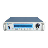
High Speed Programmable Dynamometer Controller DSP7000 series
Brand:
Magtrol
| Category:
Controller
| Size: 6 MB
Table of Contents
Safety Precautions
3
Revisions to this Manual
4
Revisions to this Manual
4
Table of Revisions
4
Table of Contents
6
Table of Contents
11
Table of Figures
11
Preface
14
Purpose of this MANUAL
14
Who Should USE this MANUAL
14
MANUAL Organization
14
Conventions USED in this MANUAL
15
1 Introduction
16
Introduction
16
Unpacking Your DSP7000
16
NEW FEATURES of the DSP7000
16
DATA Sheet
17
2 Controls
25
Controls
25
Front PANEL
25
Front PANEL Controls and Buttons
25
Figure 2-1 Front Panel
25
Enabling Saving Function
26
Enabling Secondary Functions
26
Figure 2-2 Secondary Function Menu
26
Figure 2-3 Saving Function Menu
26
How to Use Front Panel Controls and Buttons
27
VACUUM Fluorescent DISPLAY (VFD)
28
Contrast Settings
29
Status Display Messages
29
Rear Panel
30
Rear Panel Inputs and Outputs
30
Figure 2-4 DSP7001 Rear Panel
30
Figure 2-5 DSP7002 Rear Panel
30
Figure 2-6 Dynamometer Brake Output
30
Figure 2-7 TSC1/TSC2 Connector
31
Figure 2-8 Supply 1/Supply 2 Connector
31
Figure 2-9 USB Connector
31
Optional Io
32
Figure 2-10 I/O Interface Card 1 and Card 2
32
Optional Gpib
33
Optional RS-232
33
Figure 2-11 GPIB Interface
33
Figure 2-12 RS-232 Interface
33
Installation/Configuration
34
3 Installation/Configuration
34
Powering up the DSP7000
34
Self-Test
34
Figure 3-1 Program Download Display
34
Figure 3-2 Revision Display
34
Figure 3-3 Alarm Warning Display
34
Main Menu
35
Instrumentation SETUP (Torque)
35
Figure 3-4 Main Menu
35
Dynamometer Configuration Menu
36
Figure 3-5 Setup Menu
36
Figure 3-6 Dyno Setup Menu
36
Figure 3-7 Dynamometer Configuration Menu
36
Figure 3-8 Hysteresis Dynamometer Setup
37
Figure 3-9 Hysteresis Setup Menu
37
Hysteresis Dynamometer Setup
37
Figure 3-10 Hysteresis Dynamometer with Torque Transducer Setup
38
Figure 3-11 Torque Transducer Setup Menu
38
Hysteresis Dynamometer with Transducer Setup
38
Figure 3-12 Hysteresis Dynamometer with Eddy-Current or Powder Brake Setup
39
Figure 3-13 TSC2 Eddy-Current Setup Menu
39
Hysteresis Dynamometer with Eddy-Current or Powder Brake Setup
39
Eddy-Current or Powder Brake Dynamometer Setup
40
Figure 3-14 TSC2 Powder Brake Setup Menu
40
Figure 3-15 Eddy-Current or Powder Brake Dynamometer Setup
40
Figure 3-16 TSC1 Eddy-Current Setup Menu
41
Figure 3-17 TSC1 Powder Brake Setup Menu
41
Eddy-Current or Powder Brake Dynamometer with Torque Transducer Setup
42
Figure 3-18 Eddy-Current or Powder Brake Dynamometer with Torque Transducer Setup
42
Figure 3-19 TSC2 Torque Transducer Setup Menu
42
Figure 3-20 Two Eddy-Current/Powder Brake Dynamometers (Independent Setup)
43
Figure 3-21 Tandem Setup Menu
43
Two Eddy-Current/Powder Brake Dynamometers (Independent Setup)
43
Figure 3-22 Tandem Configuration Menu
44
Figure 3-22 Two Eddy-Current/Powder Brake Dynamometers (Tandem Setup)
44
Two Eddy-Current/Powder Brake Dynamometers (Tandem Setup)
44
Eddy-Current Dynamometer with Powder Brake Dynamometer (Tandem Setup)
46
Figure 3-23 Eddy-Current Dynamometer with Powder Brake Dynamometer (Tandem Setup)
46
Figure 3-24 Maximum Speed Excited Menu
47
Figure 3-25 In-Line Torque Transducer with Brake
47
In-Line Torque Transducer with Brake
47
Torque FILTER SETUP
48
Instrumentation SETUP (SPEED)
48
Figure 3-26 TSC1 Setup Menu
48
Figure 3-27 RPM Vs PPR Chart
49
Figure 3-28 Encoder Menu
50
Figure 3-29 QUAD DEG Menu
50
Quad Deg
50
Tach a
50
Configure Communication
51
Gpib Address
51
Interface
51
Figure 3-30 AI 1 Menu
51
Figure 3-31 System Setup Menu
51
Pid Settings
52
4 Pid Settings
52
About the PID Loop
52
P (Proportional Gain)
52
I (Integral)
52
D (Derivative)
52
Setting PID VALUES
52
How to Set P (Proportional Gain) Value
52
How to Set I (Integral) Value
52
How to Set D (Derivative) Value
52
Setting the Correct PID'S for Your Motor
53
Setting the PID with an Unknown Motor or System
53
Setting the PID for Torque Control
53
Figure 4-1 Open Loop Control Menu
53
Figure 4-2 Initial P Setting for Torque Control at 25
54
Figure 4-3 High Initial P Setting for Torque Control
54
Figure 4-4 Initial I Setting for Torque Control
55
Figure 4-5 Initial D Setting for Torque Control
55
Setting the PID for Speed Control
56
Figure 4-6 Initial P Setting for Speed Control at 25
56
Figure 4-7 Initial I Setting for Speed Control
57
Figure 4-8 Initial D Setting for Speed Control
57
Setting the PID for Ramp down
58
Figure 4-9 Ramp down Low I
58
Figure 4-10 Ramp down High I
59
Figure 4-11 Ramp down Dynamic I
59
Alar M System
60
5 Alar M System
60
General Information
60
Alarm Relay (Io Card Option)
60
Figure 5-1 Normal Condition "Energized Relay
60
Figure 5-2 Alarm Condition "De-Energized Relay
60
Alarm Operation
61
Figure 5-3 Typical Application
61
Figure 5-4 Alarm Enable/Disable Menu
61
Alarm Priority
62
Power ALARM
62
Instructions for Power Alarm Setup
62
Power Alarm Action
62
Figure 5-5 Max Power Menu
62
To Reset Power Alarm
63
Global Power ALARM
63
Instructions for Global Power Alarm Setup
63
Figure 5-6 Power -OL- Display
63
Figure 5-7 Power Alarm Display
63
Figure 5-8 Global Power Alarm Setup
63
Global Power Action
64
To Reset Global Power Alarm
64
Maximum SPEED ALARM
64
Instructions for Maximum Speed Alarm Setup
64
Figure 5-9 Global Power Alarm Disply
64
Figure 5-10 Speed Alarm Setup Menu
64
Maximum Speed Alarm Action
65
To Reset Maximum Speed Alarm
65
Maximum Torque ALARM
65
Instructions for Maximum Torque Alarm Setup
65
Figure 5-11 -OL- Speed Alarm Display
65
Figure 5-12 over Speed Alarm Message Display
65
Maximum Torque Alarm Action
66
To Reset Maximum Torque Alarm
66
Figure 5-13 Torque Alarm Setup Menu
66
Figure 5-14 -OL- Torque Alarm Display
66
Figure 5-15 over Torque Alarm Message Display
66
Global Torque ALARM
67
Instructions for Global Torque Alarm Setup
67
Global Torque Action
67
To Reset Global Torque Alarm
67
AIR Flow ALARM
67
Instructions for Air Flow Alarm Setup
67
Figure 5 -16 Global Torque Alarm Setup
67
Air Flow Alarm Action
68
To Reset Air Flow Alarm
68
Figure 5-17 Air Flow Alarm Setup Display
68
Figure 5-18 Air Flow Alarm Message Display
68
WATER Flow ALARM
69
Instructions for Water Flow Alarm Setup
69
Water Flow Alarm Action
69
To Reset Water Flow Alarm
69
Figure 5-19 Water Flow Alarm Setup Display
69
Figure 5-20 Water Flow Alarm Message Display
69
External ALARM (I/O CARD Option)
70
Instructions for External Alarm Setup
70
External Alarm Action
70
To Reset External Alarm
70
Figure 5-21 External Alarm Setup Display
70
Figure 5-22 External Alarm Message Display
70
TEMPERATURE ALARM (Wb/Pb Only)
71
Instructions for Temperature Alarm Setup
71
Temperature Alarm Action
71
To Reset Temperature Alarm
71
Electrical Alarm
71
Instructions for Electrical Alarm Setup
71
Electrical Alarm Action
71
Figure 5-23 Temperature Alarm Message Display
71
To Reset Electrical Alarm
72
Clutch ALARM (Wb/Pb Only)
72
Clutch Alarm Action
72
To Reset Clutch Alarm
72
Figure 5-24 Electrical Alarm Message Display
72
Figure 5-25 Clutch Alarm Message Display
72
Manually Controlled Operation
73
6 Manually Controlled Operation
73
How to SET DESIRED Power UNITS
73
How to SET DESIRED Torque UNITS
73
Figure 6-1 Power Units Menu
73
Figure 6-2 Torque Units Menu
73
How to SET Torque Control
74
Figure 6-3 Torque Control Menu
74
How to SET SPEED Control
75
Figure 6-4 Max Speed Menu
75
How to SET Open Loop Control
76
How to SET Preload Control
76
Figure 6-5 Preload Function Enabled
76
How to SET and RESET TARE Function
77
Setting the Tare Function
77
Resetting the Tare Function
77
Figure 6-6 Tare Function Enabled
77
How to SET the TM/TF INVERT Flag
78
Figure 6-7 Torque Invert Flag Screen
78
7 Computer Controlled Operation
79
Computer Controlled Operation
79
About the Usb INTERFACE
79
Usb Driver Setup for Windows Operation System
79
Checking the DSP7000-To-PC Connection for Gpib Setup
85
DATA Format
86
Output Data (Od)
86
Output Binary Command (Ob)
87
Programming
88
Data Termination Characters
88
Timeout
89
DSP7000 Command SET
89
Alarm Commands
90
Communication Commands
91
Ramp Commands
92
Setup Commands
93
Speed Commands
94
Torque Commands
96
Miscellaneous Commands
97
Quadrature Commands
98
6001 Mode
99
Figure 7-1 Setup Menu
99
Figure 7-2 System Setup Menu
99
8 Optional Equipment
100
I/O CARD 1 and I/O CARD 2
100
I/O Card Installation
100
Figure 8-1 DSP7000 Top Cover
101
Figure 8-2 IO Card Installation
101
I/O Card Interface
102
Figure 8-3 I/O Card Interface
102
I/O Card Configuration
104
Figure 8-4 Filter Channel Setup Menu
105
Figure 8-5 Offset and Gain Setup Menu
105
Figure 8-6 External Alarm Setup
105
Figure 8-7 Alarm Contact Setup
106
Figure 8-8 Torque/Speed Setup
106
Figure 8-9 Torque/Speed DAC Setup Menu
106
I/O Card 1/Card 2 Command Set
107
Optional Equipment
100
Gpib INTERFACE
108
Gpib Card Installation
108
About the Gpib Interface
109
Figure 8-10 GPIB Card Installation
109
Installing the Gpib (IEEE-488) Connector Cable
110
Changing the Gpib Primary Address
110
Figure 8-11 GPIB Installation
110
Figure 8-12 Setup Menu Display
110
Rs232 Interface
111
Installation
111
Figure 8-13 RS-232 Interface
111
Connection
112
Figure 8-15 Straight through Pin-To-Pin Cable Connection
112
Communication Parameters
113
Baud Rate
113
Checking the DSP7000-To-PC Connection
113
Gpib Communication Check
113
Figure 8-18 Connected Instruments Window
115
Figure 8-19 Communication with Instrument Window
115
RS232 Communication Check
116
Figure 8-20 Query Window
116
Figure 8-22 Tera Term Licence Agreement Window
117
Figure 8-23 Tera Term Destination Location Window
117
Figure 8-24 Tera Term Select Components Window
118
Figure 8-25 Tera Term Language Selection Window
118
Figure 8-26 Tera Term Start Menu Folder Window
119
Figure 8-27 Tera Term Additional Tasks Window
119
Figure 8-28 Tera Term Window
120
Figure 8-29 Terminal Setup Window
120
Figure 8-30 Serial Port Setup Window
121
Figure 8-31 Tera Term Window with a Command
121
Calibration
122
9 Calibration
122
Basic Calibration Process
122
Initial Calibration Procedure
122
Calibration of Analog to Digital Converters
123
Calibration of Digital to Analog Converters
124
Calibration Frequency
126
10. Theory
127
Calibration Schedule
122
Closed-Box Calibration
122
10 Theory
127
How the PID Loop Works
127
Scale Factors for Hysteresis, Eddy-Current and Powder Brake Dynamometers
127
Speed Correction for Wb (Eddy-Current Brake) Dynamometer
127
Figure 10-1 System Block Diagram
127
Equations
128
Additional SCALE Factor
128
How to Set Additional Scale Factor
128
Figure 10-2 Transposed Direct Form II Architecture
129
Filter Parameters
129
11. Troubleshooting
130
Appendix A: Inertia Correction
131
11 Troubleshooting
131
Appendix A: Inertia Correction
131
INERTIAL EFFECT on Motor TEST DATA
131
Procedure for INERTIA Correction
131
Key Conditions
132
Appendix B: Front Panel/Display Menu Flow Charts
133
PRIMARY Key Functions
133
Secondary Key Functions
134
Display both
134
Setup
134
Power Units
139
Torque Units
140
Max Speed
140
B.2.5 Max Speed
140
Scale P
141
Scale I
142
Scale D
143
Test Instrument Setup
144
Hysteresis Dynamometer Setup Menu
144
Eddy-Curennt Dynamometer Setup Menu
145
Powder Brake Dynamometer Setup Menu
146
Torque Transducer/Torque Flange Sensor Setup Menu
147
Hd5 Setup Menu
148
Eddy-Current Dynamometer with Eddy-Current Dynamometer (Tandem Setup)
149
Powder Brake Dynamometer with Powder Brake Dynamometer (Tandem Setup)
150
Eddy-Current Dynamometer with Powder Brake Dynamometer (Tandem Setup)
151
Appendix C: Schematics
152
Appendix C: Schematics
152
DSP7000 Core Block
152
DSP7000 Analog INPUTS
153
DSP7000 Digital INPUTS
154
DSP7000 Encoder in
155
DSP7000 Analog Output
156
DSP7000 Digital Output
157
Appendix D: Additional Scale Factor Table
158
Service Information
159
Advertisement
Advertisement
Related Products
Magtrol DSP6000
Magtrol DSP6001
Magtrol DES 410
Magtrol DES 411
Magtrol 4619
Magtrol 6200
Magtrol AN 2000 C
Magtrol AN Series
Magtrol Categories
Measuring Instruments
Controller
Power Supply
Transducer
Monitor
More Magtrol Manuals
Login
Sign In
OR
Sign in with Facebook
Sign in with Google
Upload manual
Upload from disk
Upload from URL