Brother TD-4000 Service Manual
Hide thumbs
Also See for TD-4000:
- User manual (80 pages) ,
- Software user's manual (40 pages) ,
- Gu (40 pages)
Table of Contents
Advertisement
Advertisement
Table of Contents
Troubleshooting

Related Manuals for Brother TD-4000


Summary of Contents for Brother TD-4000
- Page 1 SERVICE MANUAL MODEL: TD-4000/TD-4100N...
- Page 2 PREFACE This publication is a service manual covering the specifications, theory of operation, disassembly/reassembly procedure, and troubleshooting the Brother TD-4000/4100N. It is intended for service personnel and other concerned persons to accurately and quickly provide after-sale service for our TD-4000/4100N.
-
Page 3: Table Of Contents
CONTENTS CHAPTER I SPECIFICATIONS 1.1 MECHANICAL SPECIFICATIONS..................I-1 1.1.1 External Appearance ......................I-1 1.1.2 Keyboard..........................I-1 1.1.3 Display ..........................I-1 1.1.4 Printing Mechanism ......................I-2 1.1.5 Thermal Tape ........................I-2 1.1.6 Cutter..........................I-2 1.1.7 PC Interface ........................I-2 1.2 ELECTRONICS SPECIFICATIONS ..................I-2 1.2.1 Power Supply ........................I-2 CHAPTER II THEORY OF OPERATION 2.1 OUTLINE OF MECHANISMS .................... - Page 4 CHAPTER III DISASSEMBLY AND REASSEMBLY 3.1 SAFETY PRECAUTIONS..................... III-1 3.2 TIGHTNING TORQUE LISTS ..................... III-1 3.3 LUBRICATION POINTS LIST..................... III-2 3.4 DISASSEMBLY PROCEDURE.................... III-4 [ 1 ] Removing the Thermal Tape and Top Cover ASSY............. III-4 [ 2 ] Disassembling the Top Cover ASSY ................III-7 [ 3 ] Removing the Roll Guide....................
- Page 5 APPENDIX 1 SERVICEMAN SOFTWARE TOOL 1.1 Role and Use Procedure of the Reset Software Tool ............... 1-1 1.1.1 Role of the Reset Software Tool ..................1-1 1.1.2 Use Procedure of the Reset Software Tool ............... 1-1 1.2 Role and Use Procedure of the VR Adjustment Tool............... 1-3 1.2.1 Role of the VR Adjustment Tool ..................
-
Page 6: Chapter I Specifications
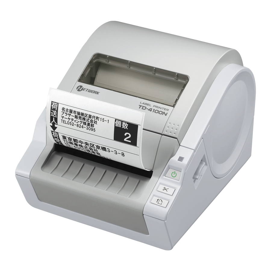
CHAPTER I SPECIFICATIONS 1.1 MECHANICAL SPECIFICATIONS 1.1.1 External Appearance (1) Dimensions (W x D x H) 173mm x 229mm x 158mm (2) Weight Approx. 1.8kg (Machine proper only) 158mm 173mm Figure 1.1-1 External Appearance 1.1.2 Keyboard (1) Number of function keys (2) Key arrangement See Fig. -
Page 7: Printing Mechanism
1.1.4 Printing Mechanism (1) Print method Direct thermal printing with thermal head Printing on thermal paper tape, and printing on thermal paper and thermal plastic tape (with fixed head and tape feeding) (2) Highest printing speed 110mm/sec (3) Print head - Type Thick film thermal head 1296 dots by one row... -
Page 8: Chapter Ii Theory Of Operation
CHAPTER II THEORY OF OPERATION 2.1 OUTLINE OF MECHANISMS 2.1.1 Print Mechanism ■ Structure of Thermal Head This machine adopts direct thermal printing system. The thermal head consists of 1296 pieces of heating elements arrayed in vertical single row as shown in the Fig. 2.1-1. -
Page 9: Press Contact And Release Mechanism Of Thermal Head
2.1.2 Press Contact and Release Mechanism of Thermal Head The head ASSY is pressed firmly against the platen by the force of spring. When the release levers L and R are pulled upwards, they are unlocked so that the platen and top cover are released. -
Page 10: Tape Feed Mechanism
2.1.3 Tape Feed Mechanism When the tape is fed, the tape is pressed against the thermal head, which is nipped between the platen and the thermal head. Here, the tape feed motor (step motor) rotates, of which drive power is transmitted via the gear train to the platen gear and the platen, and consequently the platen can feed the tape. -
Page 11: Automatic Tape Full Cutter Mechanism
2.1.4 Automatic Tape Full Cutter Mechanism The automatic tape full cutter mechanism moves the moving cutter blade up and down to the direction of the fixed cutter blade to cut the tape on the feeding pass. The cam is rotated once so that the moving cutter blade moves up and down and cuts a medium. -
Page 12: Cover Open (Cover Lock) Sensor
2.1.5 Cover Open (Cover Lock) Sensor The cover open (cover lock) sensor R (push switch) is mounted on the SB PCB ASSY. The cover open (cover lock) sensor L (push switch) is secured on the cutter unit ASSY with the screw. Closing the top cover ASSY, the cover sensor arms R and L push the cover open (cover lock) sensors (R and L) (push switch) and the signal of top cover ASSY close status is output. -
Page 13: Lock And Release Of Roll Guide
2.1.6 Lock and Release of Roll Guide Release the claw of the roll guide actuator from the gear part "A" of the upper cover by pressing the roll guide actuator. Move the roll guide shaft to the direction of the arrow "B"... -
Page 14: Outline Of Control Electronics
2.2 OUTLINE OF CONTROL ELECTRONICS Fig. 2.2-1 shows the block diagram of the control electronics. The control electronics consist of the following components. Fan motor unit Serial 220/230/240V model only Sub ASSY SW Cutter motor Cutter home position sensor CN13 CN19 CN12 CN10... -
Page 15: Button, Led Pcb (Sb Pcb
2.2.3 Button, LED PCB (SB PCB) This is the PCB equipped with POWER button, FEED button, CUT button, cover open sensor and LED lamp. 2.2.4 Cutter Home Position Sensor This sensor detects existence of the cutter at its home position. 2.2.5 Media Feed Motor (Tape Feed Motor) The media feed motor supplies the drive power to feed media. -
Page 16: Main Pcb
EEPROM 7.6MHZ (4Kbits) Photo sensor for FROM 64Mbits detecting top edge (Max. 64Mbits) of media 16bits bus TD-4100N: TD-4000: Cutter home position SDRAM 128Mbits SDRAM 64Mbits sensor (Max. 128Mbits) (Max. 64Mbits) USB IC D12 USB IF TD-4100N only LAN IC LAN 9115... - Page 17 EEPROM 7.6MHZ (4Kbits) Photo sensor for FROM 64Mbits detecting top edge (Max. 64Mbits) of media 16bits bus TD-4100N: TD-4000: Cutter home position SDRAM 128Mbits SDRAM 64Mbits sensor (Max. 128Mbits) (Max. 64Mbits) USB IC D12 USB IF TD-4100N only LAN IC LAN 9115...
-
Page 18: Logic Components
(2) Flash ROM One 64M-bits flash ROM is used, where the program, font and downloaded data are stored. (3) SDRAM TD-4000: 64M-bits TD-4100N: 128M-bits It is used when the program is executed, and when the received data is stored temporarily. -
Page 19: Key, Led Circuit
2.3.2 Key, LED Circuit - Power supply ON/OFF circuit This circuit detects the state of ON/OFF of the POWER button. Pressing this button in the power supply OFF state (LED OFF), LOW signal is sent to the CPU. Then the CPU starts initializing process and establishes the status of power supply ON (LED ON and ready for date acceptance from PC). -
Page 20: Head And Motor Power Supply On/Off Circuit
2.3.3 Head and Motor Power Supply ON/OFF Circuit Turning the CPU status of 91pin (VHON) to High, Q2 turns ON, V (25V power supply) turns ON and consequently the head and motor is energized. Turning the CPU status of 91pin (VHON) to Low, Q2 turns OFF, V (25V power supply) turns OFF and consequently the head and motor power supply is cut off. -
Page 21: Full Cutter Motor Driver Circuit And Media Feed Motor Driver Circuit
2.3.4 Full Cutter Motor Driver Circuit and Media Feed Motor Driver Circuit (1) Full cutter motor driver circuit The circuit drives the DC motor to cut a medium as described in subsection 2.1.4 "Automatic Tape Full Cutter Mechanism". When the CPU receives cut request from the key or software, it confirms that the top cover ASSY is closed, and turns VHON (91 pin) High. -
Page 22: Media Position Detect Sensor Circuit And Cover Open Sensor Circuit
Figure 2.3-6 Media Position Detect Sensor Circuit (2) Cover open sensor circuit TD-4000/4100N has the cover open sensor. It identifies open/close of the top cover ASSY from the status of mechanical switch. Opening the top cover ASSY, the contact of cover open sensor on SB PCB opens. -
Page 23: Head Temperature Detect Circuit
The change of status is sent as the signal through CN14 to CUTSEN (74 pin) of the CPU. TD-4000/4100N first confirms that the cutter stays on its' home position prior to printing. When the cutter returns to the home position, the cutter home position sensor circuit recognizes it and stops the DC motor rotation. -
Page 24: Usb Interface Circuit
2.3.9 USB Interface Circuit The CPU of TD-4000/4100N is connected with a PC using the USB cable via U14 and CN1. U14 and CPU (U12) establishes bus connection with 8-bits to send and receive the data. Figure 2.3-11 USB Interface Circuit 2.3.10 RS232C Interface Circuit... -
Page 25: Lan Interface Circuit (Td-4100N Only
2.3.11 LAN Interface Circuit (TD-4100N only) The CPU of TD-4100N is connected with a PC using the LAN cable via U1 and CN2. U1 and CPU (U12) establishes bus connection with 8-bits to send and receive the data. Figure 2.3-13 LAN Interface Circuit II - 18... -
Page 26: Safety Precautions
CHAPTER III DISASSEMBLY AND REASSEMBLY 3.1 SAFETY PRECAUTIONS (1) The disassembly or reassembly work should be carried on a grounded antistatic sheet. Otherwise, the LSIs and electronic parts may be damaged due to the electricity charged in your body. (2) When transporting PCBs, be sure to wrap them in conductive sheets such as aluminum foil. -
Page 27: Lubrication Points List
3.3 LUBRICATION POINTS LIST * Grease to be used: Grease B (one rice-grain size) Cut moving pin Cut worm gear * Grease to be used: FLOIL BG-1507 (one rice-grain size) * Grease to be used: FLOIL BG-1507 (one rice-grain size) * Grease to be used: FLOIL BG-1507 (one rice-grain size) * Grease to be used:... - Page 28 Mecha ASSY * Grease to be used: Silicon grease G501 (one rice-grain size) Double gear B Double gear C Double gear A III - 3...
-
Page 29: Disassembly Procedure
3.4 DISASSEMBLY PROCEDURE [ 1 ] Removing the Thermal Tape and Top Cover ASSY (1) Press the power button. (2) Turn OFF the main power switch. (3) Unplug the AC cord from the outlet. (4) Disconnect the AC cord from the machine. AC cord Main power switch AC cord... - Page 30 (5) Pull up the release levers L and R upwards and open the top cover ASSY. (6) Remove the thermal tape from the machine. Thermal tape Top cover ASSY Release lever L Release lever R Figure 3.4-2 Removing the Thermal Tape (7) Close the top cover ASSY loosely.
- Page 31 (9) Slide the two top cover shafts inwards to remove them, and remove the top cover ASSY. Top cover ASSY Top cover shaft Figure 3.4-4 Removing the Top Cover ASSY III - 6...
-
Page 32: 2 ] Disassembling The Top Cover Assy
[ 2 ] Disassembling the Top Cover ASSY (1) Remove the two screws and remove the side panel L from the top cover. (2) Remove the two screws and remove the side panel R from the top cover. Hook Side panel L Top cover Hook Side panel R... - Page 33 (5) Remove the left end of the platen ASSY from the top cover. (6) Remove the platen ASSY from the top cover, the platen gear and platen shaft bearing (B). Platen ASSY Top cover Platen ASSY Platen gear Platen shaft bearing (B) Figure 3.4-7 Disassembling the Top Cover ASSY (3) III - 8...
-
Page 34: 3 ] Removing The Roll Guide
[ 3 ] Removing the Roll Guide (1) Release the two hooks and remove the roll guide from the machine while pushing the roll guide actuator. Hook Hook Roll guide actuator Roll guide Figure 3.4-8 Removing the Roll Guide III - 9... -
Page 35: 4 ] Disassembling The Roll Guide
[ 4 ] Disassembling the Roll Guide (1) Release the two pins of the roll guide actuator to remove the roll guide actuator from the roll guide. (2) Remove the roll guide spring A from the roll guide actuator. (3) Slide the roll guide shaft to the left and align the three grooves of the roll guide shaft with the three ribs of the roll guide to remove the roll guide shaft from the roll guide. -
Page 36: 5 ] Removing The Insert Guide And Ground Spring
[ 5 ] Removing the Insert Guide and Ground Spring (1) Remove the one screw and remove the insert guide from the upper cover. (2) Remove the ground spring from the upper cover. Screw Insert guide Ground spring Ground spring Figure 3.4-10 Removing the Insert Guide and Ground Spring III - 11... -
Page 37: 6 ] Removing The Roll Roller Shaft And Roll Roller
[ 6 ] Removing the Roll Roller Shaft and Roll Roller (1) Remove the four roll roller shafts from the machine. (2) Remove each of the four roll rollers from the four roll roller shafts. Roll roller shaft Roll rollers Figure 3.4-11 Removing the Roll Roller Shaft and Roll Roller III - 12... -
Page 38: 7 ] Removing The Upper Cover
[ 7 ] Removing the Upper Cover (1) Turn the machine upside down. (2) Remove the four screws and remove the lower plate ASSY from the machine. Screws Lower plate ASSY Screw Screw Figure 3.4-12 Removing the Lower Plate ASSY (3) Disconnect all connectors and FFC from the main PCB ASSY. - Page 39 (4) Turn the machine upside down. (5) Remove the three screws and two screws and remove the upper cover from the machine. Screws Screws Upper cover Figure 3.4-14 Removing the Upper Cover (6) Turn the upper cover upside down. (7) Remove the filament tape which secures the harness of the tape sensor PCB ASSY. Upper cover Filament tape Figure 3.4-15 Removing the Filament Tape...
- Page 40 (8) Turn the upper cover upside down. (9) Remove the tape sensor PCB ASSY from the upper cover. Tape sensor PCB ASSY Upper cover Figure 3.4-16 Removing the Tape Sensor PCB ASSY III - 15...
-
Page 41: 8 ] Removing The Power Supply Assy And Main Pcb Assy
[ 8 ] Removing the Power Supply ASSY and Main PCB ASSY (1) Turn the machine upside down. (2) Remove the one screw and remove the heat sink DC8V from the machine. (3) Remove the two screws and remove the power supply ASSY and the DC power PCB ASSY. - Page 42 (4) Remove the DC power PCB ASSY from the power supply ASSY. NOTE: The power supply ASSY and DC power PCB ASSY are connected each other with the pins. When disassembling the DC power PCB ASSY, be careful not to bend the pins. Pins Power supply PCB DC power PCB ASSY...
- Page 43 (6) Remove the four screws and remove the ground spring plate, FG harness ASSY and main PCB ASSY from the machine. Screw Ground spring plate Screw Screw FG harness ASSY Main PCB ASSY Screw Figure 3.4-20 Removing the Main PCB ASSY (1) NOTE: Pay attention to the USB connector, serial connector and LAN connector when removing the main PCB ASSY.
- Page 44 (7) Release the hook and remove the fan from the machine. (8) Remove the shield plate ASSY from the machine. (TD-4100N only) Shield plate ASSY (TD-4100N only) Hook Figure 3.4-22 Removing the Fan and Shield Plate ASSY NOTE: From here, procedures for 100/120V model and 220/230/240V model differs. III - 19...
- Page 45 <For 100/120V model> (9) Turn the machine upside down. Release the harness of the sub ASSY SW from the three ribs of the machine. Push the hook of the connector of the sub ASSY SW and remove it from the connector of the power supply ASSY. (10) Release the two hooks to remove the sub ASSY SW from the machine.
- Page 46 (11) Turn the machine upside down. (12) Turn the power supply ASSY upside down. (13) Unsolder the harness of sub ASSY SW from the power supply ASSY. (14) Remove the sub ASSY SW. Sub ASSY SW Harness (sub ASSY SW) Soldering iron Power supply ASSY Figure 3.4-24 Removing the Sub ASSY SW (For 100/120V model) (2)
- Page 47 (15) Release the hook on both sides of the inlet and pull the inlet to the direction of the arrow as shown in the figure below to remove it. NOTE: For the hook on the lower side of the inlet, turn the under cover upside down and press the hook from the hole on the under cover.
- Page 48 <For 220/230/240V model> (9) Turn the machine upside down. Remove the filament tape from the machine. (10) Pull out the harness of sub ASSY SW from the hole of machine. Filament tape Sub ASSY SW Hole Figure 3.4-27 Removing the Filament Tape (For 220/230/240V model) (11) Release the hook on both sides of the inlet and pull the inlet to the direction of the arrow as shown in the figure below to remove it.
- Page 49 (12) Slide the harness of the inlet to the positioning hole of the fan and remove the inlet and the power supply ASSY from the machine. Power supply ASSY Inlet Positioning hole of fan Figure 3.4-29 Removing the Power Supply ASSY (For 220/230/240V model) III - 24...
-
Page 50: 9 ] Removing The Front Cover, Panel Cover And Front Side Cover
[ 9 ] Removing the Front Cover, Panel Cover and Front Side Cover (1) Remove the two screws and release the hook "A" of the front cover from the rib of the under cover. (2) Release the two hooks "B" of the front cover from the holes on the cutter unit ASSY to remove the front cover. - Page 51 (4) Pull the harness out of the hole of the machine. (5) Remove the one screw and release the pin of the panel cover from the cutter unit ASSY. Remove the panel cover from the machine while lifting up the upper side of the panel cover to the direction of the arrow.
-
Page 52: 10 ]Removing The Cutter Unit Assy And Mecha Assy
[ 10 ]Removing the Cutter Unit ASSY and Mecha ASSY (1) Take out the three harnesses from the hole of the under cover. (2) Remove the two screws and remove the cutter unit ASSY from the mecha ASSY. Harnesses Mecha ASSY Hole Harness Screws... - Page 53 (3) Pull out the harness of the tape feed motor ASSY, FG harness ASSY and the two head cables from the under cover. (4) Remove the two screws and remove the mecha ASSY from the under cover while pulling both sides of the under cover outwards. Screws Head cables Mecha ASSY...
-
Page 54: 11 ] Disassembling The Panel Cover
[ 11 ] Disassembling the Panel Cover (1) Release the harness of the SB PCB ASSY from the guide. (2) Remove the two screws and remove the SB PCB ASSY, cover sensor arm R and SB PCB sheet from the panel cover. Cover sensor arm R Screw Screw... - Page 55 (3) Remove the power button and feed button from the panel cover. (4) Remove the one screw and remove the LED guide from the panel cover. Power button Screw Feed button LED guide Panel cover Figure 3.4-37 Disassembling the Panel Cover (2) III - 30...
-
Page 56: 12 ]Disassembling The Mecha Assy
[ 12 ]Disassembling the Mecha ASSY (1) Remove the two release springs and two retaining rings from both sides of the mecha ASSY and remove the release levers L and R from the mecha ASSY. Release lever L Release spring Mecha ASSY Retaining ring Release lever R... - Page 57 (5) Remove the two screws to remove the chassis R sub ASSY from the sub plate. (6) Remove the two screws to remove the chassis L sub ASSY from the sub plate. Screws Chassis L sub ASSY Sub plate Chassis R sub ASSY Screws Figure 3.4-40 Disassembling the Mecha ASSY (3) (7) Remove the head plate from the sub plate.
- Page 58 NOTE: Be careful not to give impact on the heating element of the head ASSY. Head ASSY Heating element Figure 3.4-42 Disassembling the Mecha ASSY (5) (8) Remove the two screws and remove the head ASSY from the head plate. Head ASSY Screw Head plate...
- Page 59 (9) Remove the head cable black and head cable white from the head ASSY. (10) Remove the ferrite core from the head cable black and head cable white. Ferrite core Head cable white Head cable black Head ASSY Figure 3.4-44 Disassembling the Mecha ASSY (7) (11) Remove the two head springs from the sub plate.
- Page 60 (13) Release the two pins of the two platen supports from the chassis R sub ASSY and the chassis L sub ASSY. Remove the two platen supports from the chassis R sub ASSY and the chassis L sub ASSY. Platen supports Chassis L sub ASSY Chassis R sub ASSY Figure 3.4-46 Disassembling the Mecha ASSY (9)
-
Page 61: Reassembling Procedure
3.5 REASSEMBLING PROCEDURE [ 1 ] Reassembling the Mecha ASSY NOTE: Be careful not to cut your finger with the edge of the parts. (1) Assemble the tape feed motor ASSY and FG harness ASSY onto the chassis R sub ASSY with the two screws. NOTE: Pay attention to the direction of the tape feed motor ASSY. - Page 62 (2) Assemble the two platen supports onto the chassis L sub ASSY and the chassis R sub ASSY, and align the two pins of the platen supports with the chassis L sub ASSY and chassis R sub ASSY to secure them. Platen supports Chassis L sub ASSY Chassis R sub ASSY...
- Page 63 (3) Attach the two tapes to the sub plate. NOTE: Attach them so that the sections A and B of the tape become the same position. NOTE: Reuse the two tapes that removed from the mecha ASSY. (4) Push the two head springs into the sub plate. Tapes Head springs Tape...
- Page 64 (5) Connect the head cable black and head cable white with the connectors on the head ASSY. (6) Put the head cable black and head cable white through the ferrite core. Ferrite core Head cable white Head cable black Head ASSY Figure 3.5-4 Reassembling the Mecha ASSY (4) NOTE1: Pay attention not to give strong impact on the heating element of a head ASSY when mounting the head ASSY.
- Page 65 (7) Assemble the head ASSY onto the head plate with the two screws. NOTE: Press the head ASSY to the two bosses of the head plate and align the end of the head ASSY with the end of the head plate to secure it as shown in the figure below.
- Page 66 (8) Align the head ASSY with the head springs and assemble the sub plate. Head ASSY Head spring Head spring Sub plate Figure 3.5-7 Reassembling the Mecha ASSY (7) (9) Put the section "A" of the head ASSY into the hole "A" on the chassis R sub ASSY and assemble the chassis R sub ASSY onto the sub plate with the two screws.
- Page 67 NOTE: When assembling the chassis L sub ASSY, make sure that there is no gap on the bottom of each chassis sub ASSY. Figure 3.5-9 Reassembling the Mecha ASSY (9) (11) Insert the double gear A into the shaft of the chassis R sub ASSY and secure it with the retaining ring E2.5.
- Page 68 (14) Insert the release lever L into the shaft of the chassis L sub ASSY and secure it with the retaining ring E2.5. (15) Hang the release spring on the hook of the release lever L and the hook of the chassis L sub ASSY.
-
Page 69: 2 ] Reassembling The Panel Cover
[ 2 ] Reassembling the Panel Cover (1) Assemble the LED guide onto the panel cover with the one screw. (2) Assemble the feed button and power button onto the panel cover. Power button Screw, bind M2.6 x 8 Feed button LED guide Panel cover Figure 3.5-12 Reassembling the Panel Cover (1) - Page 70 (3) Assemble the SB PCB sheet, cover sensor arm R and SB PCB ASSY onto the panel cover and secure them with the two screws. (4) Pass the harness of the SB PCB ASSY through the guide of the panel cover as shown in the figure below.
-
Page 71: 3 ] Installing The Mecha Assy And Cutter Unit Assy
[ 3 ] Installing the Mecha ASSY and Cutter Unit ASSY (1) Put the tape feed motor harness through the ferrite core and wind up the harness once. (2) Insert the two head cables and tape feed motor harness into the hole A. (3) Insert the FG harness ASSY into the hole B. - Page 72 (4) Align the mecha ASSY with the two pins and two hooks on the under cover, then assemble the mecha ASSY with the two screws while pulling both sides of the under cover outwards evenly. Head cables Taptite, bind B M2.6 x 8 Mecha ASSY * Be sure that the head cables are not attached Hook...
- Page 73 (5) Put the two ferrite cores of the head cables and tape feed motor harness into the place provided on the under cover as shown in the figure below. Ferrite core Ferrite core Head cables Under cover Tape feed motor harness Figure 3.5-16 Installing the Mecha ASSY (3) (6) Bind the harnesses of the cutter unit ASSY with the fastening band.
- Page 74 (7) Assemble the cutter unit ASSY to the under cover with the two screws while paying attention to the harnesses inside. (8) Pass the cutter unit harnesses and the cutter home position sensor harness through the hole of the under cover as shown in the figure below. NOTE: Confirm that the cutter unit harnesses and the cutter home position sensor harness pass through the under of the release lever L, R.
-
Page 75: 4 ] Installing The Front Side Cover, Panel Cover And
[ 4 ] Installing the Front Side Cover, Panel Cover and Front Cover (1) Hang the hook of the front side cover on the under cover and align the pin with the cutter unit ASSY, then assemble the front side cover with the one screw. Cutter unit ASSY Front side cover Hook... - Page 76 (2) Hang the hook of the panel cover on the under cover and align the pin with the cutter unit ASSY, then assemble the panel cover with the one screw. NOTE: Confirm that the harness of the SB PCB ASSY pass through the under of the release lever R.
- Page 77 (4) Assemble the cover sensor arm L into the front cover. Cover sensor arm L Front cover Figure 3.5-23 Installing the Cover Sensor Arm L III - 52...
- Page 78 (5) Insert the two hooks "A" of the front cover into the holes of the cutter unit ASSY. (6) Hang the hook "B" of the front cover on the under cover. (7) Secure the front cover and the under cover with the two screws. Taptite, bind B M3 x 8 Under cover Hooks "A"...
-
Page 79: 5 ] Installing The Main Pcb Assy And Power Supply Assy
[ 5 ] Installing the Main PCB ASSY and Power Supply ASSY NOTE: 100/120V model and 220/230/240V model have different procedures. <For 100/120V model> (1) Insert the connector of the inlet into the hole of the machine. Power supply ASSY Inlet Connector Hole... - Page 80 (2) Pass the inlet through the positioning hole of the fan from the inside of the machine and slide the harness to the positioning hole of the inlet, then set the inlet to the machine. NOTE: Make sure that the hooks of the inlet are locked on the under cover securely. Harness Under cover Hook...
- Page 81 (3) Pass the harness of the sub ASSY SW through the hole of the machine as shown in the figure below. (4) Solder the harness of the sub ASSY SW to the power supply ASSY. Harness (sub ASSY SW) Hole Sub ASSY SW Hole Harness (sub ASSY SW)
- Page 82 (5) Turn the machine upside down. (6) Assemble the sub ASSY SW on the machine. NOTE: Confirm that the circular mark of the sub ASSY SW is set outward. (7) Connect the connector of the sub ASSY SW to the connector of the power supply ASSY.
- Page 83 <For 220/230/240V model> (1) Pass the inlet through the positioning hole of the fan from the inside of the machine and slide the harness to the positioning hole of the inlet, then set the inlet to the machine. NOTE: Make sure that the hooks of the inlet are locked on the under cover securely. Harness Under cover Hook...
- Page 84 (2) Turn the machine upside down. (3) Pass the harness of sub ASSY SW through the two ribs and hole of the machine, and secure it with the filament tape as shown in the figure below. Filament tape (35mm) Sub ASSY SW 25mm Ribs Hole...
- Page 85 (4) Turn the machine upside down. (5) Assemble the shield plate ASSY on the machine. (TD-4100N only) (6) Assemble the fan into the machine and hang on the hook. NOTE: Confirm that the connector of the fan is in the direction of the following figure. Shield plate ASSY (TD-4100N only) Hook...
- Page 86 (8) Connect the power supply harness to the power supply ASSY. Power supply harness Power supply ASSY Figure 3.5-34 Connecting the Power Supply Harness (9) Connect the DC power PCB ASSY to the power supply ASSY. NOTE: Be careful not to break the pins between the DC power PCB ASSY and power supply ASSY.
- Page 87 (10) Assemble the power supply ASSY and the DC power PCB ASSY onto the machine and secure it with the two screws. NOTE: When assembling the DC power PCB ASSY and the power supply ASSY, be careful not to bend the pin. NOTE: Hang the harness of the sub ASSY SW and the inlet on the two ribs of the machine.
- Page 88 <For 220/230/240V model> Taptite, bind B M2.6 x 8 Taptite, bind B M2.6 x 8 Heat sink DC8V Power supply ASSY DC power PCB ASSY Inlet Figure 3.5-38 Installing the Power Supply ASSY, DC Power PCB ASSY and Heat Sink DC8V (For 220/230/240V model) Main PCB ASSY Inlet...
-
Page 89: 6 ] Installing The Upper Cover
[ 6 ] Installing the Upper Cover (1) Assemble the tape sensor PCB ASSY onto the upper cover. Tape sensor PCB ASSY Upper cover Figure 3.5-40 Installing the Tape Sensor PCB ASSY III - 64... - Page 90 (2) Turn the upper cover upside down. (3) Bend the FFC of the tape sensor PCB ASSY as shown in the figure below, and secure it with the filament tape so that do not contact the section "A" and "B" of the upper cover.
- Page 91 (5) Turn the machine upside down. (6) Connect all connectors and FFC to the main PCB ASSY. (7) Hang the harnesses on the slits of the machine. Tape feed motor ASSY Head ASSY Power supply PCB Slit Main PCB ASSY Fan motor Tape sensor DC power PCB ASSY...
-
Page 92: 7 ] Installing The Roll Roller And Roll Roller Shaft
[ 7 ] Installing the Roll Roller and Roll Roller Shaft (1) Assemble each of the four roll rollers to the four roll roller shafts. (2) Assemble the four roll roller shafts onto the machine. NOTE1: Install the roll roller shafts until them click. NOTE2: Confirm that the roll rollers rotate smoothly. -
Page 93: 8 ] Installing The Ground Spring And Insert Guide
[ 8 ] Installing the Ground Spring and Insert Guide (1) Insert the ground spring into the boss of the upper cover, and hang the section "A" on the hole so that the section "B" contact the end face of the roll roller shaft. NOTE: Set the ground spring into the boss of the upper cover surely. -
Page 94: 9 ] Reassembling The Roll Guide
[ 9 ] Reassembling the Roll Guide (1) Assemble the roll guide spring B onto the roll guide shaft. (2) Assemble the roll guide shaft into the positioning hole of the roll guide, and slide the roll guide shaft to the direction of the arrow. Align the three groove parts of the roll guide shaft with the three ribs of the roll guide to assemble the roll guide shaft to the roll guide. - Page 95 NOTE3: Push the roll guide actuator and confirm that the roll guide shaft moves smoothly. Roll guide Roll guide actuator Roll guide shaft Figure 3.5-48 Reassembling the Roll Guide (2) III - 70...
-
Page 96: 10 ]Installing The Roll Guide
[ 10 ]Installing the Roll Guide (1) Assemble the roll guide onto the machine while pushing the roll guide actuator. NOTE: Press the roll guide actuator and confirm that the claws of the roll guide actuator and the roll guide slide smoothly without contacting the upper cover. -
Page 97: 11 ] Reassembling The Top Cover Assy
[ 11 ] Reassembling the Top Cover ASSY (1) Insert the shaft (cut surface side) of the platen ASSY into the arm of the right hand side of the top cover, the platen shaft bearing (B) and the platen gear. (in this order) (2) Put the other end of the platen ASSY into the notch of the hole at the left hand side of the top cover. - Page 98 (5) Hang the hook of the side panel R on the positioning hole of the top cover, and secure the side panel R onto the top cover with the two screws. NOTE: Confirm that the pins of the inside of the top cover engage with the hole of the side panel R.
-
Page 99: 12 ]Installing The Top Cover Assy And Thermal Tape
[ 12 ]Installing the Top Cover ASSY and Thermal Tape (1) Put the top cover ASSY into the slit on the under cover. (2) Insert the two top cover shafts from the inside of the hooks on the top cover until they hit the end of the hooks. - Page 100 (4) Assemble the thermal tape onto the machine. (5) Close the top cover ASSY. Thermal tape Top cover ASSY Figure 3.5-55 Installing the Thermal Tape III - 75...
-
Page 101: 13 ]Energization Check
[ 13 ]Energization Check (1) Apply the probes of the tester to the roll roller shaft and the lower plate ASSY, and check the energization. Condition of energization: 10 or less In the case of non energization: Check the following points. Is the ground spring correctly set? Is the ground spring normally? (Refer to... -
Page 102: 14 ]Demonstration Print And Final Check
[ 14 ]Demonstration Print and Final Check (1) Insert the AC cord into a outlet. (2) Confirm that the main power switch of the rear side is ON. (3) Turn OFF the power supply switch of the front side. (4) After setting a widest label (102mm), press the FEED button six times continuously as holding down the POWER button in the power-off condition. -
Page 103: Chapter Iv Troubleshooting And Error Message
CHAPTER IV TROUBLESHOOTING AND ERROR MESSAGE This section gives the service personnel some of the troubleshooting procedures to be followed if an error or malfunction occurs with this machine. It is impossible to anticipate all of the possible troubles which may occur in future and determine the troubleshooting procedures, so this chapter covers some sample troubles. - Page 104 4.3 ERROR MESSAGE A list of the error messages that are indicated while the service person tool is being used is shown below. Check Item Error Error Messages Advices (0) Write default Communication Cannot transmit. Check the power supply and EEPROM data error the USB connector.
-
Page 105: Troubleshooting Flows
4.4 TROUBLESHOOTING FLOWS [ 1 ] Printing is performed with specific dots omitted. Printing is performed with specific dots omitted. The thermal head and the platen are dirty. Are the thermal head and the platen dirty? Clean the thermal head and the platen. -
Page 106: 2 ] Led Does Not Turn On
[ 2 ] LED does not turn ON. LED does not turn ON. Or LED turns on temporarily. Is the cable of Correct the connection. power supply connected correctly? Turn ON the main power switch. Is the main power switch ON? Is the cable of SB PCB Correct the connection. -
Page 107: 3 ] No Printing Is Performed
[ 3 ] No printing is performed. Tape feed is normal but cannot print. Is the direction Set the roll in the correct of the roll correctly? direction. Is the print head cable connected correctly? Correct the connection. Is the head cable of the correct color connected? Any devices on the main PCB are... -
Page 108: 4 ] The Usb Interface Malfunction
[ 4 ] The USB interface malfunction. The interface malfunction. Is the USB cable Correct the connection. connected correctly? Are the printer driver Re-install the driver and editor and P-touch editor installed correctly. onto the PC correctly? Is the USB mode Set to the USB mode. -
Page 109: 5 ] The Rs232C Interface Malfunction
[ 5 ] The RS232C interface malfunction. The interface malfunction. Is the RS232C cable Correct the connection. connected correctly? Is the interlink cable Use the interlink cable. (cross) used? Are the printer driver Re-install the driver and editor and P-touch editor installed correctly. -
Page 110: 6 ] The Ethernet Interface Malfunction
[ 6 ] The ethernet interface malfunction. The interface malfunction. Is the ethernet cable Correct the connection. connected correctly? Is the interlink cable Use the interlink cable. (cross) used? Are the printer driver Re-install the driver and editor and P-touch editor installed correctly. -
Page 111: 7 ] The Tape Is Not Cut
[ 7 ] The tape is not cut. The tape is not cut. Is the cutter Assemble the cutter unit unit assembled correctly? Is the harness assembled or harness correctly. correctly? Press the POWER, CUT Are there any or FEED button to jammed tape or the like between the blades? reverse the cutter. -
Page 112: 8 ] The Tape Is Not Fed Correctly
[ 8 ] The tape is not fed correctly. The tape feed is not correctly. Try to print after replace a new tape cassette. Repair completed. Is tape feed normal? The old tape cassette is defective. Is the paper passed under the insert guide? (Is the paper set Insert the paper between the transmission sensor?) -
Page 113: 9 ] The Tape Is Fed, But The Error Message Appears Shortly
[ 9 ] The tape is fed, but the error message appears shortly. The tape is fed, but the error message appears shortly. Is the VR adjustment performed correctly? Correct the adjustment. * Refer to "APPENDIX 1 SERVICEMAN SOFTWARE TOOL". Is the flat cable of the Replace the tape sensor tape sensor ASSY damaged? -
Page 114: Appendix 1 Serviceman Software Tool
1.1.2 Use Procedure of the Reset Software Tool (1) Connect the machine (TD-4000 or TD-4100N) to your PC with the USB cable and turn the POWER button ON. (2) When there is not a driver in your PC, "Found New Hardware Wizard" screen is displayed. - Page 115 (3) Start the reset software tool (File name: TD4000tstReset.exe) to initialize the EEPROM, and check the serial number. (Reset software tool (TD4000tstReset.exe) is shared by the TD-4000 and TD- 4100N.) Double-click Figure 2. Reset software tool (a) “Reset EEPROM” Reset the EEPROM of the machine to the factory settings.
-
Page 116: Role And Use Procedure Of The Vr Adjustment Tool
Role of the VR Adjustment Tool This tool serves to perform the VR adjustment. If replace the PCB, perform this adjustment. (VR adjustment tool (TD4000tstVRAdjust.exe) is shared by the TD-4000 and TD- 4100N.) 1.2.2 Use Procedure of the VR Adjustment Tool (1) Connect the machine to your PC with the USB cable and turn the POWER button (2) When there is not a driver in your PC, "Found New Hardware Wizard"... -
Page 117: Setting And Use Procedure Of The Serviceman Software Tool
In this case, click the "Cancel" button. (Refer to Figure (3) Start the serviceman software tool (TD4000tstSE.exe). (The file names of the tool of the TD-4000 and TD-4100N are the same name.) This screen is TD-4100N. In the case of TD-4000, the operation is same. - Page 118 (4) Click the "General setting…" button. Figure 7. Setting screen (a) “RS test port” Set the COM port number to be used for the "RS test". (Default: COM1) When the setting is not known, the procedure of investigating the COM port number that can be used with PC is indicated to the end of this chapter.
-
Page 119: Use Procedure Of The Serviceman Software Tool
1.3.3 Use Procedure of the Serviceman Software Tool When perform the "Read serial no" and "Read MAC Address", the subsequent inspection can be performed. The inspection order is not specified. When initialize the EEPROM with the reset tool, perform all inspections. * When perform the inspection of the TD-4100N, the inspection log is output. - Page 120 (2) Read the MAC Address (Read MAC Address) (TD-4100N only) This inspection is only TD-4100N. Read the MAC address from the machine. Read the MAC address information of the PCB on the machine. The MAC address cannot be changed. 1) Click the "Read MAC Address" button. After a few seconds, the reading MAC address is displayed in the "MAC Address"...
- Page 121 3) If the process is correctly completed, the message that writing is successful and the EEPROM version appear in the "Results" column. This screen is TD-4100N. In the case of TD-4000, operation is the same. Click and start the process. If default value writing is successful, the EEPROM version is displayed.
- Page 122 (4) Check the Tape Sensor (Tape sensor check) Inspect whether the tape sensor works correctly. 1) Click the "Tape sensor check" button. Figure 12. Check the tape sensor 2) Set the release coated paper (Cord: LP847301 Name: 80GS OJI ROLL ASSY) to the sensor part of the machine so that the sandpapery surface is the upper side.
- Page 123 (5) Check the Cover Sensor (Cover sensor check) Inspect whether the cover sensor works correctly. 1) Click the "Cover sensor check" button. Figure 14. Check the cover sensor 2) Open and close the top cover of the machine. The message in the "Results" column is changed to "off"...
- Page 124 (6) Check the Fan (Fan check) Inspect whether the fan works correctly. 1) Click the "Fan check" button. Figure 17. Check the fan 2) Click the "Fan ON" button in the dialog box shown to turn the fan. 3) Confirm the fan turning and click the "Fan OFF" button to stop the fan. Turn the fan.
- Page 125 (7) Feed & Cut Test (Cut test) Inspect whether the tape feeding and the tape cutting work correctly. 1) Click the "Cut test" button. Figure 20. Feed & Cut test 2) Set the free length roll (102mm) into the machine, and press the FEED button on the machine.
- Page 126 (8) Check the Printing Head Temperature (Temperature check) Inspect whether the thermistor works correctly. The acceptance range is 10 to 65 degrees C. 1) Click the "Temperature check" button. Figure 22. Check the printing head temperature 2) The temperature sensor value is displayed in the "Results" column. 3) If the result is "OK", proceed to the next inspection.
- Page 127 (9) Adjustment Print Test (Adjustment print test) Print the print pattern for inspection and adjust the margin. 1) Click the "Adjustment print test" button. Figure 24. Adjustment print test 2) The "Adjustment print test" screen is displayed. Figure 25. "Adjustment print test" screen 1 - 14...
- Page 128 3) Set the free length roll (102mm) into the machine and click the "Print test (continuous) (A)" button to print the print pattern for inspection. The print pattern by a default is the following figure. 4) Measure the top margin on the print result and make sure that it is 3mm±0.25mm.
- Page 129 5) Set the die cut roll (51mm x 26mm) into the machine and click the "Print test (50mm 1Label) (C)" button to print the print pattern for inspection. The print pattern by a default is the following figure. 6) Measure the top margin on the print result and make sure that it is 3mm±0.25mm.
- Page 130 7) If printing of the free length roll (102mm) and the die cut roll (51mm x 26mm) are finished, the "OK" button is enabled. If the adjustment of the margin is completed, click the "OK" button. If not, click the "NG" button. Then, proceed to the next inspection.
- Page 131 2) When finishing writing, the result is displayed in the "Results" column. 3) If the judgement is "OK", the writing is correctly completed. This screen is TD-4100N. In the case of TD-4000, operation is the same. Write the serial number. If the writing is correctly completed, the message is displayed.
- Page 132 Number". 3) Turn the POWER button ON. 4) Click the "RS test" button. This screen is TD-4100N. In the case of TD-4000, operation is the same. Start the communication test. The communication test result is displayed. The judgement is "OK".
- Page 133 Caution: When the RS-232 communication test fails, the following errors occur. 1) The "Error!" is displayed in the "Results" column. As for the error cause, have cause that the RS-232C cable of the PC side or the machine side is not connected.
-
Page 134: Check Procedure Of Com Port Number
1.3.4 Check Procedure of COM Port Number The RS-232C communication test use the COM port that is set in the "RS test port" on the "General settings" screen. When differ in the COM port with RS-232C cable and the "RS test port" setting, the communication test fails. Check the following procedure to find the COM port of the PC. - Page 135 (3) Select the "System". Figure 38. "Performance and Maintenance" screen (4) If the "System Properties" screen is displayed, click the "Device Manager" on the "Hardware" tab. Figure 39. "System Properties" screen (5) The devices on the PC are listed. Click the "+" of the "Ports (COM & LPT)". There is the "Communications Port (COM*)".
-
Page 136: Auto Power Off Setting Tool
Performing in wrong order would cause invalid auto power OFF setting in the product. <Conditions> 1) Part code of the mounted main PCB ASSY is: LBC102001 (TD-4000), or LBC103001 (TD-4100N). 2) Model code of the product is listed in table below. - Page 137 (3) Once the driver is installed, double-click "autopoff.exe" to run "Automatic Power OFF Setting Tool". Select the connected printer in the "Printer:" field. Check that the "Auto power-off time:" field shows "None" and click the "Apply" button. Select the printer here. Double-click Figure 41.
- Page 138 Caution: When the auto power OFF setting is failed on writing, the window below appears. 1) When the connected printer is not same with printer selected on "Auto Power OFF Setting Tool", error message below appears. Check the "Printer:" field on "Auto Power OFF Setting Tool"...
- Page 139 Dec., 2009 SM-PT031...
Need help?
Do you have a question about the TD-4000 and is the answer not in the manual?
Questions and answers