Sign In
Upload
Manuals
Brands
Themis Manuals
Server
X8DTL-i
Themis X8DTL-i Manuals
Manuals and User Guides for Themis X8DTL-i. We have
1
Themis X8DTL-i manual available for free PDF download: Installation Manual
Themis X8DTL-i Installation Manual (146 pages)
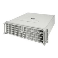
3RU 19” Rack-Mount Rugged Enterprise Server with Motherboard Configuration / Two Quad-Core 5500 or Quad / Six-Core 5600 Xeon CPUs
Brand:
Themis
| Category:
Server
| Size: 3 MB
Table of Contents
Installation Manual
3
Safety Precautions
4
Warnings and Cautions
4
Safety Instructions
6
Grounding Methods
7
Table of Contents
9
Preface
21
Figure 1 Rugged Enterprise Server Model RES-32XR3-S
21
Table 1 RES-X2Xr3 20" Chassis Manual Matrix (AC and DC Power Supplies)
22
Table 2 RES-X2Xr3S / RES-X1Xr3 17" Chassis Manual Matrix (AC and DC Power Supplies)
23
Table 3 RES-X2Xr3/Fio 16" Chassis Manual Matrix (AC and DC Power Supplies)
24
1 Overview and Specifications
27
Overview
27
Figure 1-1 RES-32XR3-S
27
Table 1-2 RES-32XR3-S Major Features
28
Figure 1-2 X8DTL-6 Motherboard Block Diagram
29
Figure 1-3 External Features of RES-32XR3-S (Front and Rear)
30
System Leds and I/O Connectors
31
Table 1-3 System Leds
34
Table 1-4 I/O Connectors
35
Chipset Overview
36
Main Features of the 5500 Series Processor and the 5500 Chipset
36
Special Features
37
Recovery from AC Power Loss
37
PC Health Monitoring
37
Fan Status Monitor with Firmware Control
37
Environmental Temperature Control
37
System Resource Alert
38
ACPI Features
38
Slow Blinking LED for Suspend-State Indicator
38
Main Switch Override Mechanism
39
Wake-On-LAN (WOL)
39
Super I/O
39
Overview of the Winbond WPCM450R Controller
40
Specifications
40
General
40
Table 1-5 RES-32XR3-S General Specifications
40
Electrical
42
System Power
42
Table 1-6 RES-32XR3-S Electrical Specifications
42
Output Voltage
43
Environmental
43
Electrostatic Discharge
43
Noise
43
Shock
43
Packaging and Shipping
47
Accessory Kit
47
Rack-Mount Slides (Optional)
48
Table 1-7 Approximate Weights of the RES Series
48
2 Installation and Operation
49
Installation Procedures
49
Remove Protective Top Cover
49
Memory Modules
51
Installation and Operation
51
Installation
52
Figure 2-2 Remove the Air-Flow Deflector Screws
53
Figure 2-3 Memory Module Slot Locations
54
Figure 2-4 Memory Module Removal
54
PCI Cards
55
Figure 2-5 PCI Card Installation
55
Installing Cards
55
Lithium Battery
56
Figure 2-6 PCI Card Clamp
56
Remove Protective Top Cover
56
Removing the Lithium Battery
56
Installing a Lithium Battery
57
SAS/SATA Storage Drive
57
Storage Drive Removal
59
Storage Drive Installation
60
Removable 120-MM Fan
60
Removing and Installing a 120-MM Fan
61
Power Supply
62
Removing a Power Supply
62
Power Supply
63
Installing a Power Supply
64
Rack Mounts
65
Mounting Brackets
65
Rack-Mount Slides (Optional)
65
Figure 2-13 Right Rack-Mount Bracket
65
Operation
66
Plugging in the AC Power Cords
66
Turning the System on
66
Getting Started
67
Configuration
67
Linux Installation
67
Turning the System off
68
3 BIOS Setup Utility
69
Introduction
69
Starting BIOS Setup Utility
69
How to Change the Configuration Data
70
Starting the Setup Utility
70
Main Setup
71
System Time/System Date
71
Figure 3-1 Main BIOS Setup Screen
71
Supermicro X8DTL-6 Motherboard
72
Processor
72
System Memory
72
Advanced Setup Configurations
73
Boot Features
73
Figure 3-2 Advanced Settings
73
Quick Boot
73
Quiet Boot
73
Addon ROM Display Mode
74
Bootup Num-Lock
74
Hit 'Del' Message Display
74
Power Button Function
74
PS/2 Mouse Support
74
Restore on AC Power Loss
74
Wait for 'F1' if Error
74
Watch Dog Function
74
Interrupt 19 Capture
75
Processor and Clock Options
75
Clock Spread Spectrum
75
CPU Ratio
75
Hardware Prefetcher (Available When Supported by the CPU)
75
Ratio CMOS Setting (Available When the Item-CPU Ratio Is Set to Manual)
75
Adjacent Cache Line Prefetch (Available When Supported by the CPU)
76
Execute-Disable Bit Capability (Available When Supported by the os and the CPU)
76
Intel® Virtualization Technology (Available When Supported by the CPU)
76
MPS and ACPI Ordering
76
Active Processor Cores
77
C-State Package Limit Setting (Available When Intel® C-State Tech Is Enabled)
77
C1E Support
77
Intel® C-STATE Tech
77
Intel® EIST Technology
77
Intel® Turboboost Technology (Available When EIST Technology Is Enabled)
77
Simultaneous Multi-Threading (Available When Supported by the CPU)
77
C1 Auto Demotion (Available When the C-State Tech Is Enabled)
78
C3 Auto Demotion (Available When the C-State Tech Is Enabled)
78
ACPI T State
78
DCA Technology
78
DCA Prefetch Delay
78
Advanced Chipset Control
78
QPI Links Speed
79
QPI Frequency (Available When QPI Links Speed Is Set to Full Speed)
79
QPI L0S and L1
79
Memory Frequency
79
Memory Mode
79
Demand Scrubbing
79
Patrol Scrubbing
80
Channel Interleave/Bank Interleave
80
Throttling - Closed Loop / Throttling - Open Loop
80
Intel VT-D
81
SR-IOV Support
81
NUMA Support
81
Intel I/OAT
81
Active State Power Management
82
USB Functions
82
USB 2.0 Controller
82
Legacy USB Support
82
IDE/SATA Configuration
82
SATA#1 Configuration
82
IDE Detect Timeout (Sec)
83
Primary IDE Master/Slave, Secondary IDE Master/Slave, Third IDE Master, and Fourth IDE Master
83
Dma Mode
84
Pio Mode
84
Pci/Pnp Configuration
85
Clear NVRAM
85
Plug & Play os
86
PCI Latency Timer
86
PCI IDE Busmaster
86
PCI-Express I/O Performance
86
ROM Scan Ordering
86
Slot 1 PCI 33Mhz, Slot 2 PCI 33Mhz, Slot 3 PCIE X4 1.0 in
86
Boot Graphics Adapter Priority
87
Load Onboard LAN1 Option Rom/Load Onboard LAN2 Option ROM
87
Load Onboard SAS Option ROM
87
Onboard LAN Option ROM Select
87
Serial Port1 Address/Serial Port2 Address
87
Super IO Device Configuration
87
Flow Control
88
Redirection after BIOS POST
88
Remote Access
88
Remote Access Configuration
88
Serial Port Mode
88
Serial Port Number
88
CPU Overheat Alarm
89
Hardware Health Monitor
89
Sredir Memory Display Delay
89
Terminal Type
89
VT-UTF8 Combo Key Support
89
CPU 1 Temperature/Cpu 2 Temperature/System Temperature
90
Fan Speed Control Modes
91
System Temperature
91
ACPI APIC Support
92
ACPI Aware O/S
92
ACPI Configuration
92
High Performance Event Timer
92
PS2 KB/MS Wake up
92
Voltage Readings
92
ACPI Version Features
93
Apic Acpi Sci Irq
93
Headless Mode
93
TCG/TPM (Trusted Platform Module) Support
93
Trusted Computing
93
IPMI Configuration
94
IPMI Firmware Revision
94
Status of BMC
94
View BMC System Event Log
94
Clear BMC System Event Log
95
Set LAN Configuration
95
Channel Number
95
Channel Number Status
95
IP Address Source
96
Event Log Configuration
97
Clear Event Log
97
Mark All Events as Read
97
PCIE Error Log
97
View Event Log
97
Security Settings
98
Supervisor Password
98
User Password
98
Change Supervisor Password
98
Figure 3-3 Security Settings
98
User Access Level (Available When Supervisor Password Is Set as Above)
99
Change User Password (Available When a User Password Is Installed)
99
Clear User Password (Available Only When User Password Is Installed)
99
Password Check (Available When a Password Is Installed)
99
Boot Sector Virus Protection
99
Boot Configuration
100
Boot Device Priority
100
Storage Drives
100
Figure 3-4 Boot Settings
100
Removable Drives
101
CD/DVD Drives
101
Retry Boot Devices
101
Exit Options
102
Save Changes and Exit
102
Discard Changes and Exit
102
Figure 3-5 Exit Options
102
Discard Changes
103
Load Optimal Defaults
103
Load Fail-Safe Defaults
103
BIOS Recovery
103
Boot Sector Recovery from a USB Device
104
Boot Sector Recovery from an IDE CD-ROM
104
Boot Sector Recovery from a Serial Port ("Serial Flash")
104
Requirements
104
Figure 3-6 AMI_FLSH Hyperterminal
106
Figure 3-7 ROM File Extraction
107
Figure 3-8 Flash Recovery
107
BIOS Error Beep Codes
108
Appendix A. Connector Pinouts
109
PS/2 Keyboard and Mouse
109
USB Ports
110
Serial Port
110
VGA Display Port
111
Gigabit Ethernet LAN Ports
112
IPMI Dedicated LAN Port (X8DTL-6F Only
112
Figure A-4 Ethernet Connector, Type RJ45
112
Figure
112
Appendix B. Rack-Mount Slide Installation
113
Figure B-1 Screw Locations for Rack-Mount Slides
113
Appendix C. Red hat Enterprise Linux 5 Installation
117
Introduction
117
Installation
118
Figure C-1 Power on after Linux DVD Is Inserted into Drive
118
Figure C-2 Skip Key
118
Figure C-3 Welcome Screen
119
Figure C-4 Language Selection
119
Figure C-5 Selecting Layout Type
120
Figure C-6 Enter Installation Number
120
Figure C-7 Partitioning
121
Figure C-8 Reviewing Option
122
Figure C-9 Creating a Custom Layout
123
Figure C-10 Setting up Boot Loader
124
Figure C-11 Master Boot Record (MBR
125
Figure C-12 Network Devices List
126
Figure C-13 Edit Interface Pop-Up Screen
127
Figure C-14 Selecting Time Zone
128
Figure C-15 Setting up Root Account and Password
129
Figure C-16 Package Installation Default Screen
130
Figure C-17 Optional Packages
131
Appendix D. Optional Remote On/Off Switch
135
Remote On/Off Configuration
135
Remote On-Only Configuration
136
Ordering the Remote On/Off Switch
136
Appendix E. Re-Packing Instructions
137
Re-Packaging for Shipment
137
Packing Components
137
Instructions for Re-Packing
138
Packaging Components
138
Advertisement
Advertisement
Related Products
Themis X8DTL-6
Themis X8DTL-6F
Themis X8DTL-3
Themis X8DTL-3F
Themis X8DTL-iF
Themis XV1 Series
Themis XV1/1
Themis XV1/2
Themis XV1/3
Themis 200
Themis Categories
Server
Barcode Reader
Motherboard
Laboratory Equipment
Video Card
More Themis Manuals
Login
Sign In
OR
Sign in with Facebook
Sign in with Google
Upload manual
Upload from disk
Upload from URL