Table of Contents
Advertisement
Quick Links
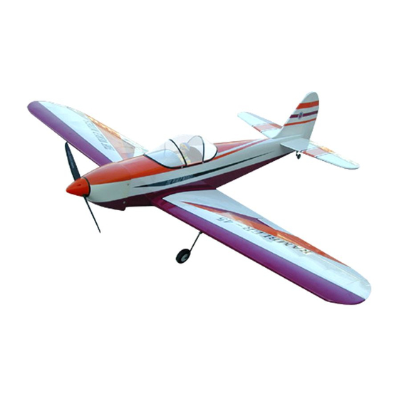
RAMBLER-45
EXPERIENCED
FLIER
中 上 者 向
0.4
0-0.46
0.60-0.72 cu. In. displacement 4-stroke
R
equire : 5-channel
Wing Span
Wing Area
Flying Weight
Fuselage Length
Warning !This model is not a toy.
It is designed for maximum performance. Please seek advice if one is not familiar with this kind
of engine powered precision model. Operating this model without prior preparation may cause
injuries. Remember, safety is the most important thing. Always keep this instruction manual at
hand for quick reference.
cu. in. displacement 2-stroke
s
and1lowprofileretractservo
* Specifications are subject to change without notice.*
radiow/5standardservos
Specifications
63.0 in / 1600 mm
660 sq in / 42.6 sq dm
6.0 lbs / 2700 g
51.0 in / 1290 mm
INSTRUCTION MANUAL
FACTORY PRE-FABRICATED
ALMOST-READY-TO-FLY (ARF) SERIES
MADE IN CHINA
Advertisement
Table of Contents

Related Manuals for THE WORLD MODELS RAMBLER-45


Summary of Contents for THE WORLD MODELS RAMBLER-45
- Page 1 INSTRUCTION MANUAL RAMBLER-45 EXPERIENCED FLIER 中 上 者 向 0-0.46 cu. in. displacement 2-stroke 0.60-0.72 cu. In. displacement 4-stroke equire : 5-channel radiow/5standardservos and1lowprofileretractservo Specifications Wing Span 63.0 in / 1600 mm Wing Area 660 sq in / 42.6 sq dm Flying Weight 6.0 lbs / 2700 g...
-
Page 2: Before You Begin
RAMBLER-45 I N D E X BEFORE YOU BEGIN P. 1 PARTS LIST P. 2 ASSEMBLY P.3-P.10 SAFETY PRECAUTIONS P. 10 BEFORE YOU BEGIN Read through the manual before you begin, so you will have an overall idea of what to do. -
Page 3: Parts List
Parts List 1. MAIN WING -- 1 pair 12. SCREW PB2x16mm -- 6 pcs TRI-HORN M3x14mm (For Elevator) (L) -- 2 sets 2. SCREW PB2x25mm -- 6 pcs FUEL TUBE Ø6x5mm -- 2 pcs FUEL TUBE Ø6x5mm -- 4 pcs CLEVIS--2 pcs CLEVIS -- 2 pcs PUSHROD Ø1.8x615mm w/ Threads (For Elevator) -- 2 pcs... -
Page 4: Aileron Servo
Aileron A p p l y i n s t a n t t y p e C A g l u e t o b o t h s i d e s o f e a c h h i n g e . Aileron Servo Lead Bottom View Aileron Servo... -
Page 5: Retractable Landing Gear
Retractable Landing Gear 3mm Set Screw 4.1mm collar KA3x14mm Retract Servo Set Screw 3 X 3mm L i n k a g e C o n n e c t o r Washer R-side L-side Select the servo horn that will give 26mm travel when it rotates through 180°... -
Page 6: Tail Landing Gear
Vertical Fin & Rudder Apply instant type CA glue to both sides of each hinge. C=C' Completed Tail Landing Gear Screw PA3x12mm PA3x 12mm Set Screw Collar 2.1mm 1 . 5 m m 3mm Set Screw 2 m m Engine Mount M4x 25mm Socket Head Screw Washer d4 x D9mm... -
Page 7: Fuel Tank
Fuel Tank Fuel Tank 320cc Balsa 10x10x107mm (For Fuel Tank Position F ixing ) Balsa 4x6x45mm Fuel Tank 320cc Fuel Tank 320cc Balsa 10x10x107mm (For fuel tank position fixing ) Plywood 3x45x112mm Bottom View Engine M3.5x 30mm SOCKET HEAD SCREW Washer 3.5mm 3.5mm... -
Page 8: Elevator Pushrod
Elevator Pushrod Screw PB 2 x 16 mm PB 2 x 16mm Clevis Fuel Tube Ø6x5mm Ø 1mm pilot holes for World Models tri-horn are pre-drilled. Tri-horn Please look for pin-hole marks at under side of control surfaces. M3 x 22mm(L) Ø... - Page 9 Canopy First insert the grommet to the canopy then apply screw. Screw PWA2.3 X 12mm PC001063 A/B d1.5 x D6.5 mm Silicon Grommet PWA2.3 x 12mm d1.5xD6.5mm Silicon Grommet Main Wing M4 x 40mm SOCKET HEAD SCREW Washer d4 x D15mm d4xD15mm Washer M4x40mm...
-
Page 10: Control Throws
Control Throws Adjust the control throws as shown in the diagram. These throws are good for general flying. You can adjust according to your Elevator personal preference. 18mm 18mm Rudder 43mm 43mm Aileron 9 mm C.G. The ideal C.G. position is 100mm(3.9in)behind the leading edge measured at where the wing meets the fuselage. - Page 11 Usage of the transparent 3D template This transparent 3D template is used for position guidance of the actual cutting of the pre-painted cowling. Simply cut the transparent 3D template to fit your engine and exhaust pipe, then slide onto the actual cowling and use as template to mark the openings required for final cutting.
- Page 12 LINKAGE CONNECTOR HW7111050 & HW7111060 Drill 2mm hole at servo horn. Insert linkage connector into servo horn. Make sure shoulder of screw is cleared from servo horn. Add washer to reduce play if necessary. Shoulder Tighten up the round nut against the shoulder.
- Page 13 The World Models Manufacturing Co., LTD. www .thew orldm odels .com A099PO19040812...
Need help?
Do you have a question about the RAMBLER-45 and is the answer not in the manual?
Questions and answers