Sign In
Upload
Manuals
Brands
FireClass Manuals
Control Panel
FC501-HK
FireClass FC501-HK Manuals
Manuals and User Guides for FireClass FC501-HK. We have
4
FireClass FC501-HK manuals available for free PDF download: Installation Manual, Quick Start Setup Manual, User Manual
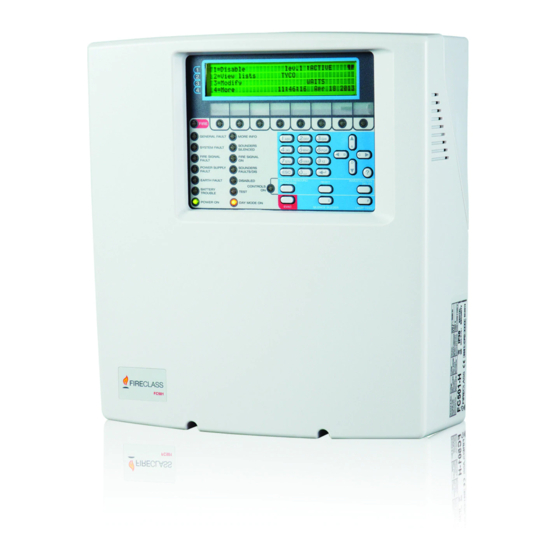
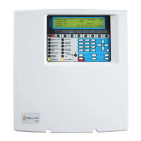
FireClass FC501-HK Installation Manual (88 pages)
FC501 series Addressable Fire Control Panels
Brand:
FireClass
| Category:
Control Panel
| Size: 3.9 MB
Table of Contents
Table of Contents
3
Introduction
5
FC501 Fire Control Panel
5
Accessory Items
5
Description
5
Input
5
Outputs
5
Operating Features
6
Interface
8
Access to Signalling and Commands
8
Users and Installers Features
9
Power Supply
9
Description of the FC500REP Repeater Signalling
10
FC500REP Repeater Control Keys
10
FC500REP Repeater LED Description
10
Description of the Control Keys (Panel)
11
The Status LED
12
Parts Identification
13
Description of Parts
14
Installation
17
Installing the Control Panel
17
Control Panel Closure
17
Installing FC500REP Repeater
19
Description of the Terminals
19
Loop
19
Telephone Line
19
Fire
19
Fault
20
Audio Station
20
Auxiliary Outputs
20
Rs485
21
Battery
21
The System Wiring
21
Connecting Addressable Devices
21
Connecting Repeater FC500REP
22
Connecting Output Devices
24
Bell Outputs
24
Connecting the Power Supply
25
Thermal Probe
26
Installing FC500IP Board
27
Installing the 38Ah Battery Metal Box
28
Maintenance
28
Pc Programming
31
Installation
31
Select Language
31
Software Window Look
31
Control Panel Connections
31
Main Window
32
Icons
32
File Menu
32
Tools Menu
33
Help Menu
33
Panel Details
33
Panel Details Menu
33
Communication Menu
34
Language Menu
34
Firmware Update Menu
35
Screensaver Menu
35
Account Menu
35
Programming Pages
36
Loop Devices Programming
36
Description of the Icons in the Tool Bar
36
Loop Wiring Calculation
37
Detectors Parameters Programming
37
Input Module Parameters Programming
38
Output Module Parameters Programming
39
Multiple Input-Output Module - Parameters
40
Programming (FC410MIO/FC410QIO)
40
Manual Call Point Parameters Programming
40
Zones Programming
41
Outputs Programming
42
SC1, SC2 Outputs
42
OC1, OC2 Outputs
42
Relay Outputs
43
General Options Programming
43
General Output Settings
45
Panel Setting for Simphony Sounders and Panel
45
Setting for AV Base Sounder
45
Communicators Programming
45
Clock
47
Log
47
Utilities
48
Battery Calculation
48
User Mode
49
Graphic Maps
50
Disable
50
Programming from the Panel
53
Using the System
53
Operating the System from the Panel
53
Alphanumeric Entry (Editing Text)
53
Assistant Text Composition
54
Single Selection
54
Multiple Selection
54
Date and Time
54
Numeric Entry
54
Main Page - Accessing the System
55
Insert Password
55
Programming Page
56
KEY - Insert Modify Password
56
KEY- Auto Enrolling (Autolearning)
57
Automatic Zones Assignment
57
Sounders Triggered by
58
Warning Enrolling (Autolearning)
58
Auto Addressing Procedure
59
KEY -Device
60
Choose the Loop (See User Manual View Devices)60
60
Choose the Device
60
Loop Devices Programming Page
61
KEY - SW Zone
61
SW Zone in WALK TEST
61
Sounders on (3S)
62
Smoke Delay (60S/30Min)
62
Delay to Alarm
62
DLY ALARM TIME (Min)
62
Key- Output
63
Choose Output
63
Set as Sc1
63
Panel Alarm Trigger
63
Disablement Trigger
63
Key- Network
64
Key - Map Device
65
Key -Usb
65
Key -System
66
Panel ID
66
Day / Night / Auto
66
Delay to Alarm Time
67
Copy on Zone
67
Monst. Output Time
67
Enable Screen Saver
67
Wire Loops
67
KEY- Restore Default
68
FC500REP Repeater Address
68
Modify
69
Accessing the Modify Menu
69
Disable
71
Accessing the Disable Menu
71
Key - Password (Disable)
71
Select the Password
71
Disable Password
71
Key- Sounders
71
Quick Start-Up Procedure
73
Procedure
73
System Default
75
Zone Assignment
75
System Default Parameters
75
Accessory
79
Universal Base
79
FC460H or FC400H-Addressable Heat Detector
79
FC460P or FC400P - Addressable Optical Smoke
79
FC460PH or FC400PH - Addressable Optical Smoke & Heat Detector
79
FC460PC Addressable Optical Smoke & Heat Detector & CO
80
FC410LI - Line Isolator Module
80
FC410MIM - Mini Input Module
80
FC410MIO - Small Addressable Multi I/0 Module
80
FC410SIO - Single Input/Output Module
80
FC420CP - Addressable Break Glass Callpoint (Indoor)
80
FC421CP - Addressable Break Glass Callpoint (Outdoor)
80
FC430SAB/SAM - Sounder Base Address Modules
80
FC430SB - Loop Low Power Sounder Base
81
I - Isolator Base
81
FC490ST - Loop Service Tool
81
FC410BDM - Beam Detector Module
81
FC410CIM - Contact Input Module
81
FC410DIM - Detector Input Module
81
FC410RIM - Relay Interface Module
81
FC400CH - Addressable Carbon Monoxide + Heat Detector
81
801RIL - Remote LED Indicator
82
801HL - Remote LED Indicator
82
HVR800-High Voltage Relay
82
Dpk4/Dpki
82
FIRERAY 50/100-Optical Beam Smoke Detector
82
Fireray 3000
82
Fireray 5000
82
FC410LPSY and FC410LPAV Loop Powered Sounders and Sounder-Beacons
83
FC410LPBS-R/W Loop Powered Sounders and Sounder-Beacons (EN54-23)
83
FC430LPSB and FC430LPASB Loop Powered Addressable Sounder/Beacon Base
83
FC430LPBSB Loop Powered Addressable Sounder/Beacon Base (EN54-23)
83
FC410SNM Sounder Notification Module
84
FC410TSM - Door Control Module
84
FC410DDM - Universal Fire and Gas Detector Module
84
FC410QIO Quad Input Output Module
84
FC410QRM Quad Relay Module
84
FC410QMO Quad Monitored Output Module
84
Specifications
85
Technical Features
85
Description of the Terminals
85
Table of Distribution of Currents
87
Advertisement
FireClass FC501-HK Quick Start Setup Manual (52 pages)
Addressable Fire Control Panel
Brand:
FireClass
| Category:
Control Panel
| Size: 1.17 MB
Table of Contents
Italiano
2
Table of Contents
2
Italiano
3
Note Importanti
3
Sicurezza Elettrica E Requisiti Dei Cavi
3
Requisiti Dei Cavi
4
Tipi DI Cavo
4
Messa a Terra
4
Schermatura
4
Passaggio Dei Cavi
4
Rete RS485
4
Alimentazione DI Rete
4
FASE 1 - Montaggio Della Centrale
5
FASE 2 - Controlli Preventivi Alla Messa in Servizio
5
FASE 3 - Installazione Delle Batterie
6
FASE 4 - Messa in Servizio
6
Controlli Della Centrale
6
Tasto Help
7
Procedura DI Autoindirizzamento
8
Programmazione Degli Indirizzi Dei Dispositivi
8
Utilizzando Il Programmatore
8
Aggiunta Informazioni DI Testo E Zona Senza
9
Software
9
Collaudo E Monitoraggio Dei Dispositivi
9
Procedura Per Walk-Test
9
FASE 5 Opzioni DI Menu Utili
10
Come Visualizzare Il Registro Eventi
10
Videata Controllo Loop
10
Come Visualizzare lo Stato Dei Dispositivi
10
Come Disattivare I Punti
10
Come Disabilitare Le Sirene
10
Come Caricare Nella Centrale, una Lingua Presente in una Chiavetta USB
10
English
12
English
13
Important Notes
13
Cable Requirements
14
Cable Routing
14
Cable Types
14
Earthing
14
Mains Supply
14
RS 485 Networking
14
Screening
14
STEP 1 - Mounting the Panel
15
STEP 2 - Pre Commissioning Checks
15
STEP 3 - Install the Batteries
16
STEP 4 Commissioning
16
Panel Checks
16
HELP Key
17
Auto Addressing Procedure
17
Programming Device Addresses Using the Programmer
18
Adding Text and Zone Information Without
19
Software
19
Testing the Devices and Monitoring
19
Walk Test Procedure
19
STEP 5 Useful Menu Options
19
How to Access the Event Log
19
Loop Check Screen
20
How to View the Device Status
20
How to Disable Points
20
How to Disable Sounders
20
How to Load a Language Present in a USB Stick
20
Español
22
Espanol
23
Notas Importantes
23
Alimentación de la Red Eléctrica
24
Blindaje
24
Conexión a Tierra
24
Encaminamiento de Los Cables
24
Interconexión a la Red RS 485
24
Requisitos de Los Cables
24
Tipos de Cables
24
PASO 1 - Montaje de la Central
25
PASO 2 - Comprobaciones Previas a la Puesta en Servicio
25
PASO 3 Instalacion de las Baterias
26
PASO 4 Puesta en Servicio
26
Comprobaciones de la Central
26
Tecla AYUDA
27
Procedimiento de Direccionamiento Automatico
27
Programar las Direcciones de Los Dispositivos
28
Usando el Programador
28
Añadir Texto E Información de la Zona sin Software
29
Probar Los Dispositivos y Monitorear
29
Procedimiento de Prueba Caminando (Walk Test)
29
PASO 5 Opciones Utiles del Menu
30
Como Acceder al Registro de Eventos
30
Pantalla de Comprobación del LAZO
30
Como Ver el Estado de un Dispositivo
30
Como Inhabilitar Puntos
30
Como Inhabilitar Sirenas
30
Cómo Cargar un Idioma Presente en un Lápiz de Memoria USB
30
Português
32
Notas Importantes
33
Portugues
33
Alimentação Eléctrica
34
Blindagem
34
Encaminhamento Do Cabo
34
Ligação Em Rede RS 485
34
Ligação À Terra
34
Requisitos Dos Cabos
34
Tipos de Cabos
34
PASSO 1 - Instalar a Central
35
PASSO 2 - Verificações de Pré-Arranque
35
PASSO 3 - Instalar as Baterias
36
PASSO 4 - Colocação Em Funcionamento
36
Verificacoes da Central
36
Tecla AJUDA
37
Procedimento de Enderecamento Automatico
37
Programar Enderecos Do Dispositivo Usando O Programador
38
Adicionar Texto E Informação da Zona Sem Software
38
Ensaiar os Dispositivos E Monitorizar
39
Procedimento de Teste de Percurso
39
PASSO 5 Opções Uteis de Menu
39
Como Aceder Ao Registo de Evento
39
Ecrã de Verificação Do Loop
40
Como Visualizar O Estado Do Dispositivo
40
Como Desactivar os Pontos
40
Como Desactivar os Dispositivos Acusticos
40
Como Carregar um Idioma Presente Em um Pendrive USB
40
Dutch
42
Belangrijke Opmerkingen
43
Nederlands
43
Aarding
44
Kabelroutering
44
Kabeltypes
44
Kabelvoorschriften
44
Netspanning
44
RS 485 Netwerken
44
Schermen
44
STAP 1 - Bevestig Het Paneel
45
STAP 2 - Controles Vóór Ingebruikname
45
STAP 3 - Installeer de Accu's
46
STAP 4 Ingebruikname
46
Controles Van Het Paneel
46
HELP-Toets
47
Procedure Voor Auto-Adressering
47
Programmeerapparaat Adressen Met de
48
Toevoegen Van Tekst en Zone Informatie Zonder
48
Software
48
Testen Van de Elementen en de Bewaking
49
Procedure Looptest
49
STAP 5 Handige Menu-Opties
49
Toegang Tot Het Gebeurtenislog
49
Controlescherm Voor de Lus
50
Elementstatus Bekijken
50
Het Uitschakelen Van de Punten
50
Het Uitschakelen Van de Sirenes
50
Een Taal Aanwezig Op Een USB-Stick Laden
50
FireClass FC501-HK Quick Start Setup Manual (52 pages)
Addressable Fire Control Panel
Brand:
FireClass
| Category:
Control Panel
| Size: 0.65 MB
Table of Contents
Table of Contents
2
Italiano
3
Note Importanti
3
Requisiti Dei Cavi
4
Tipi DI Cavo
4
Messa a Terra
4
Schermatura
4
Passaggio Dei Cavi
4
Rete RS 485
4
Alimentazione DI Rete
4
FASE 1 - Montaggio Della Centrale
4
FASE 2 - Controlli Preventivi Alla Messa in Servizio
5
FASE 3 - Installazione Delle Batterie
5
FASE 4 - Messa in Servizio
6
FASE 5 - Opzioni DI Menu Utili
10
English
13
Important Notes
13
Cable Requirements
14
Cable Types
14
Earthing
14
Screening
14
Cable Routing
14
RS 485 Networking
14
Mains Supply
14
STEP 1 - Mounting the Panel
14
STEP 2 - Pre-Commissioning Checks
15
STEP 3 - Install the Batteries
15
STEP 4 - Commissioning
16
STEP 5 - Useful Menu Options
20
Español
23
Notas Importantes
23
Requisitos de Los Cables
24
Tipos de Cable
24
Puesta a Tierra
24
Blindaje
24
Tendido de Los Cables
24
Interconexión a la Red RS 485
24
Alimentación Eléctrica
24
PASO 1 - Montaje de la Central
24
PASO 2 - Comprobaciones Previas a la Puesta en Servicio
25
PASO 3 - Instalación de las Baterías
25
PASO 4 - Puesta en Servicio
26
PASO 5 - Opciones Útiles del Menú
30
Português
33
Notas Importantes
33
Requisitos Dos Cabos
34
Tipos de Cabos
34
Ligação À Terra
34
Blindagem
34
Encaminhamento Do Cabo
34
Ligação Em Rede RS 485
34
Alimentação Eléctrica
34
PASSO 1 - Instalar a Central
34
PASSO 2 - Verificações de Pré-Arranque
35
PASSO 3 - Instalar as Baterias
35
PASSO 4 - Colocação Em Funcionamento
36
PASSO 5 - Opções Úteis de Menu
40
Nederlands
43
Belangrijke Opmerkingen
43
Kabelvereisten
44
Kabeltypes
44
Aarding
44
Schermen
44
Kabels Leggen
44
RS 485 Netwerken
44
Netvoeding
44
STAP 1 - Bevestig Het Paneel
44
STAP 2 - Controles Vóór Ingebruikname
45
STAP 3 - Installeer de Accu's
45
STAP 4 - Ingebruikname
46
STAP 5 - Handige Menuopties
50
Advertisement
FireClass FC501-HK User Manual (36 pages)
FC501 series Addressable Fire Control Panel
Brand:
FireClass
| Category:
Control Panel
| Size: 0.57 MB
Table of Contents
Table of Contents
3
Introduction
5
FC501 Fire Control Panel
5
Accessory Items
5
User Access Level
5
User Interface
6
Description of Keys
6
Panel Command Keys Description (Table 1)
6
Reset
6
Silence/Resound/Sounders
6
Key Help
7
Signalling
7
The Status Leds
7
Buzzer (Audible Signals)
7
Description of the Repeater FC500REP Leds
7
Display
7
Start-Up Page
7
Front Page
7
Main Page
7
Diagnostic Pages MENU Page
7
Front
9
The EVENT DRIVEN Pages
10
Warning Status
10
Delay to Alarm STATUS
11
Alarm Status
12
Fault Status
13
Locate Loop Break Pages
14
Locate the Not Addressed Devices
14
View-Log-Parameters
15
View Parameters
15
KEY - View Loop
16
View of Loop Details
16
KEY - View Devices
16
Select the Loop
16
Select the Device
16
View Device Data on the Loop
17
KEY- View SW Zone
18
KEY- View Output
18
KEY- View NETWORK
19
Key- Communicators
19
KEY- View Option
20
KEY - View Log
20
View Log
20
Key - View FW Version
21
Key-Panel
21
View Lists
22
Modify
23
Modify Menu
23
KEY -INIT MSG (Modify Panel Label)
23
KEY - User Password
24
Insert or Modify Password
24
Key-Day/Night
24
Day/Night Mode
24
Key-Time and Date
25
Key- Clear LOG
25
Key- Walk Test
26
Disable
27
Key - Disable List
28
Key - Devices (Disable)
28
Select the Loop
28
Select the Device
28
Disable Device on the Loop
28
Key - SW Zone
29
Select SW Zone
29
Disable SW Zone
30
Key - Outputs
30
Select the Output
30
Disable Output
30
Key - Network
30
Select the Network Device
30
Disable Network Device
30
Key - COMMUNIC. (Disable)
31
Select the COMMUNIC. Device
31
Disable COMMUNIC. Device
31
Key-Password (Disable)
32
Select the Password
32
Disable Password
32
Key - Fire Relay
32
Repeater FC500REP Signalling
33
Description of Command Keys
33
Lcd Display Description
33
EVENT DRIVEN Page Description
33
Description of Status LED
33
Advertisement
Related Products
FireClass FC501-L
FireClass FC501-H
FireClass FC501 Series
FireClass FC503
FireClass FC506
FireClass FC500
FireClass FC-P-S
FireClass FC32-1
FireClass FC500IP
FireClass FC500MFI
FireClass Categories
Control Panel
Fire Alarms
I/O Systems
Control Unit
Smoke Alarm
More FireClass Manuals
Login
Sign In
OR
Sign in with Facebook
Sign in with Google
Upload manual
Upload from disk
Upload from URL