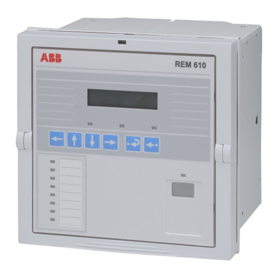
ABB REM 610 Technical Reference Manual
Motor protection relay
Hide thumbs
Also See for REM 610:
- Technical reference manual (158 pages) ,
- Operator's manual (68 pages) ,
- Product manual (36 pages)
Table of Contents
Advertisement
Quick Links
Advertisement
Table of Contents

Related Manuals for ABB REM 610


Summary of Contents for ABB REM 610
- Page 1 REM 610 Motor Protection Relay Technical Reference Manual...
-
Page 3: Table Of Contents
4.1.4. Protection .................22 4.1.4.1. Block diagram ............22 4.1.4.2. Thermal overload protection ......22 4.1.4.3. Start-up supervision ...........29 4.1.4.4. Short-circuit protection ........30 4.1.4.5. Undercurrent protection ........31 4.1.4.6. Earth-fault protection ..........31 4.1.4.7. Unbalance protection .........32 © Copyright 2005 ABB Oy, Distribution Automation, Vaasa, FINLAND... - Page 4 4.1.13.IEC 60870-5-103 remote communication protocol ..62 4.1.14.Modbus remote communication protocol ......65 4.1.14.1.Protocol overview ..........65 4.1.14.2.Profile of Modbus REM 610 ....... 66 4.1.15.SPA bus communication protocol parameters ....78 4.1.15.1.Event codes ............92 4.1.16.Self-supervision (IRF) system .......... 96 4.1.16.1.Self-supervision of the RTD module ....
- Page 5 ................127 5.2.6. Earth-fault protection in a solidly earthed network ..127 6. Ordering information ............129 7. Revision history of REM 610 ..........131 7.1. Revision identification ...............131 7.2. Changes and additions to the earlier released revision A ..131 8. References ................132 9.
-
Page 6: Introduction
Interface (MMI), and to the Installation Manual for installation of the relay. 1.2. The use of the relay REM 610 is a versatile multifunction protection relay mainly designed to protect motors in a wide range of motor applications. REM 610 is based on a microprocessor environment. A self-supervision system continuously monitors the operation of the relay. - Page 7 REM 610 Motor protection Relay 1MRS 752263-MUM Technical Reference Manual • three additional galvanically isolated digital inputs • Disturbance recorder • recording time up to 80 seconds • triggering by one or several internal or digital input signals • records four analogue channels and up to eight user-selectable digital channels •...
-
Page 8: Guarantee
REM 610 Motor Protection Relay 1MRS 752263-MUM Technical Reference Manual 1.4. Guarantee Please inquire about the terms of guarantee of your nearest ABB representative. 1.5. Revision history Version Date Remarks 26.10.2004 Front page picture and front view figures updated. 02.03.2005 Sections 1.1., 1.3., 3.3., 4.1.1.8., 4.1.4.4., 4.1.4.6., 4.1.4.10.,... -
Page 9: Safety Information
REM 610 Motor protection Relay 1MRS 752263-MUM Technical Reference Manual Safety information Dangerous voltages can occur on the connectors, even though the auxiliary voltage has been disconnected. National and local electrical safety regulations must always be followed. The device contains components which are sensitive to electrostatic discharge. -
Page 10: Instructions
The relay can be used with both circuit-breaker controlled and contactor controlled drives. REM 610 can equally well be used to protect, for instance, feeder cables and power transformers which require thermal overload protection and, for instance, single-, two- or three-phase overcurrent or non-directional earth-fault protection. - Page 11 REM 610 Motor protection Relay 1MRS 752263-MUM Technical Reference Manual Fig. 3.3.-1 Connection diagram, example 1...
- Page 12 REM 610 Motor Protection Relay 1MRS 752263-MUM Technical Reference Manual Fig. 3.3.-2 Connection diagram, example 2...
- Page 13 REM 610 Motor protection Relay 1MRS 752263-MUM Technical Reference Manual Fig. 3.3.-3 Connection diagram, example 3...
-
Page 14: Technical Description
REM 610 Motor Protection Relay 1MRS 752263-MUM Technical Reference Manual Technical description 4.1. Functional description 4.1.1. Product functions 4.1.1.1. Schema of product functions Three-phase thermal overload protection I L1 I L2 Motor start-up supervision based on thermal stress calculation I L3... -
Page 15: Inputs
4.1.1.4. Outputs REM 610 is provided with three power outputs (PO1, PO2 and PO3) and two signal outputs (SO1 and SO2). Switchgroups SGR1...5 are used for routing internal signals from the protection stages, the motor start-up signal and the external trip signal to the desired signal or power output. -
Page 16: Motor Start Up
REM 610 Motor Protection Relay 1MRS 752263-MUM Technical Reference Manual The estimated time to the next possible motor start up, i.e. when the restart inhibit signal is reset, can be accessed either via the HMI or the SPA bus. Note! If the restart inhibit function has been activated (SGF1/7=0), SGR3 will be overridden. -
Page 17: Disturbance Recorder
4.1.1.11. Non-volatile memory REM 610 can be configured to store various data in a non-volatile memory, which will retain its data also in case of loss of auxiliary voltage (provided that the battery has been inserted and is charged). Operation indication messages and LEDs, the... -
Page 18: 13.Time Synchronization
REM 610 Motor Protection Relay 1MRS 752263-MUM Technical Reference Manual IRF codes can indicate: • no response on the output contact test • faulty program, work or parameter memory • internal reference voltage error In case of a warning, the relay will continue to operate with full or reduced functionality and the green indicator LED (ready) will remain lit as during normal operation. -
Page 19: Measurements
REM 610 Motor protection Relay 1MRS 752263-MUM Technical Reference Manual when second-pulse synchronization is used, only year-month-day-hour-minute- second. The relay’s real-time clock will be rounded to the nearest whole second or minute, depending on whether second- or minute-pulse synchronization is used. -
Page 20: Configuration
REM 610 Motor Protection Relay 1MRS 752263-MUM Technical Reference Manual Table 4.1.2-1 Measured values Indicator Description RTD5 Temperature from RTD5 RTD6 Temperature from RTD6 Thermistor1, resistance value Thermistor2, resistance value Optional 4.1.3. Configuration Fig. 4.1.3.-1 illustrates how the internal and digital input signals can be configured... - Page 21 REM 610 Motor protection Relay 1MRS 752263-MUM Technical Reference Manual Fig. 4.1.3.-1 Signal diagram...
-
Page 22: Protection
REM 610 Motor Protection Relay 1MRS 752263-MUM Technical Reference Manual The functions of the relay are selected with the switches of switchgroups SGF, SGB, SGR and SGL. The checksums of the switchgroups are found under SETTINGS in the HMI menu. The functions of the switches are explained in detail in the corresponding SG_ tables. - Page 23 REM 610 Motor protection Relay 1MRS 752263-MUM Technical Reference Manual The full load current of the motor is defined by means of the protected unit scaling factor and determines the thermal trip level of stage θ>, θ . The set safe stall time, , determines the operate time of the stage for a load current of 6 x FLC without prior load.
- Page 24 REM 610 Motor Protection Relay 1MRS 752263-MUM Technical Reference Manual The reduced ability of the motor to cool down during standstill is taken into account by setting the cooling time constant to be longer than the heating time constant. The...
- Page 25 REM 610 Motor protection Relay 1MRS 752263-MUM Technical Reference Manual 4000 3000 2000 1000 1.05 Fig. 4.1.4.2.-1 Trip curves when no prior load and p=20...100%...
- Page 26 REM 610 Motor Protection Relay 1MRS 752263-MUM Technical Reference Manual 4000 3000 2000 1000 10 15 20 1.05 Fig. 4.1.4.2.-2 Trip curves at prior load 1 x FLC and p=100%...
- Page 27 REM 610 Motor protection Relay 1MRS 752263-MUM Technical Reference Manual 4000 3000 2000 1000 1.05 Fig. 4.1.4.2.-3 Trip curves at prior load 1 x FLC and p=50%...
- Page 28 REM 610 Motor Protection Relay 1MRS 752263-MUM Technical Reference Manual 4000 3000 2000 1000 1.05 Fig. 4.1.4.2.-4 Trip curves at prior load 1 x FLC and p=20%...
-
Page 29: Start-Up Supervision
REM 610 Motor protection Relay 1MRS 752263-MUM Technical Reference Manual 4.1.4.3. Start-up supervision Start-up supervision can be based on either definite-time overcurrent protection or thermal stress calculation. The selection is made in SGF3, the default being thermal stress calculation. Start-up supervision based on definite-time overcurrent... -
Page 30: Short-Circuit Protection
REM 610 Motor Protection Relay 1MRS 752263-MUM Technical Reference Manual The operate time is calculated as below. However, the shortest possible operate time of stage I is ~300 ms. > × > t s [ ] ------------------------------------------- where t = operate time >... -
Page 31: Undercurrent Protection
REM 610 Motor protection Relay 1MRS 752263-MUM Technical Reference Manual Note! If the PU scale has been set to 0.5, the maximum measured rated current (FLC) is 25 x In. It is possible to block the tripping of the high-set overcurrent stage by applying a digital input signal to the relay. -
Page 32: Unbalance Protection
REM 610 Motor Protection Relay 1MRS 752263-MUM Technical Reference Manual To prevent the contactor in a contactor controlled drive from operating at too high phase currents, the earth-fault stage can be set to be inhibited when one or several phase currents exceed the FLC of the motor four, six or eightfold. The selection is made in SGF4. -
Page 33: Phase Reversal Protection
REM 610 Motor protection Relay 1MRS 752263-MUM Technical Reference Manual The figure below illustrates the inverse-time curves of stage I >. K=20 K=40 K=100 > = 0.5 x I > = 0.2 x I > = 0.1 x I 1000... -
Page 34: Cumulative Start-Up Time Counter
REM 610 Motor Protection Relay 1MRS 752263-MUM Technical Reference Manual 4.1.4.9. Cumulative start-up time counter The cumulative start-up time counter detects too frequent start-up attempts, which cause overheating of the motor. The start-up time of every motor start up is added to a register, Σt . -
Page 35: 11.Temperature Protection (Optional)
REM 610 Motor protection Relay 1MRS 752263-MUM Technical Reference Manual The CBFP will not be triggered in case of: • an alarm or a trip of the thermal protection stage • an alarm or a trip a temperature stage • a trip of the phase reveral stage •... - Page 36 REM 610 Motor Protection Relay 1MRS 752263-MUM Technical Reference Manual Note! RTD6 can be used to measure the ambient temperature for the thermal protection stage. In this case, Ta6> and Tp6> will not be in use. This state will be indicated by dashes on the LCD and by “-999”...
- Page 37 REM 610 Motor protection Relay 1MRS 752263-MUM Technical Reference Manual RTD temperature vs resistance Resistance values (Ω) of RTD sensors at specified temperatures are presented in the table below. Table 4.1.4.11-1 Resistance values of RTD sensors Platinum Nickel Copper Nickel TCR 0.00385...
- Page 38 REM 610 Motor Protection Relay 1MRS 752263-MUM Technical Reference Manual ThA> Alarm1 ThA> Alarm (RTD) RTD1/ Trip1 Thermistor1 (RTD) ThA> Trip Trip1 (Th) Alarm2 RTD2 Trip2 Alarm3 RTD3 Trip3 ThB> Alarm4 ThB> Alarm (RTD) RTD4/ Trip4 Thermistor2 (RTD) ThB> Trip...
-
Page 39: 12.Settings
REM 610 Motor protection Relay 1MRS 752263-MUM Technical Reference Manual 4.1.4.12. Settings There are two alternative setting groups available, setting groups 1 and 2. Either of these setting groups can be used as the actual settings, one at a time. Both groups have their related registers. - Page 40 REM 610 Motor Protection Relay 1MRS 752263-MUM Technical Reference Manual Table 4.1.4.12-1 Setting values Setting Description Setting range Default setting Σt Restart inhibit value 5...500 s ∆Σt /∆t Countdown rate of start-up time 2...250 s/h 2 s/h counter CBFP Operate time of CBFP 0.10...60.0 s...
- Page 41 REM 610 Motor protection Relay 1MRS 752263-MUM Technical Reference Manual Switchgroups and parameter masks The settings can be altered and the functions of the relay selected in the SG_ selector switchgroups. The switchgroups are software based and thus not physical switches to be found in the hardware of the relay.
- Page 42 REM 610 Motor Protection Relay 1MRS 752263-MUM Technical Reference Manual SGF1...SGF5 Switchgroups SGF1...SGF5 are used for configuring the desired function as follows: Table 4.1.4.12-2 SGF1 Default Switch Function setting SGF1/1 Selection of the latching feature for PO1 SGF1/2 Selection of the latching feature for PO2...
- Page 43 REM 610 Motor protection Relay 1MRS 752263-MUM Technical Reference Manual Table 4.1.4.12-3 SGF2 Default Switch Function setting SGF2/1 Operation mode of the alarm indication of stage θ> SGF2/2 Operation mode of the start indication of stage I > SGF2/3 Operation mode of the start indication of stage I>>...
- Page 44 REM 610 Motor Protection Relay 1MRS 752263-MUM Technical Reference Manual Table 4.1.4.12-5 SGF4 Default Switch Function setting SGF4/1 and Inhibition of stage I > when one or several phase currents SGF4/2 exceed the FLC of the motor SGF4/1 SGF4/2 SGF4/3 Selection of ambient temperature •...
- Page 45 REM 610 Motor protection Relay 1MRS 752263-MUM Technical Reference Manual Table 4.1.4.12-7 SGB1...SGB5 Default Switch Function setting SGB1...5/3 • 0 = indications and memorized values are not cleared and latched output contacts are not unlatched by the digital input signal •...
- Page 46 REM 610 Motor Protection Relay 1MRS 752263-MUM Technical Reference Manual q> Weighting SGR1...5/1 Alarm factor q> SGR1...5/2 Trip SGR1...5/3 > SGR1...5/4 > SGR1...5/5 I>> SGR1...5/6 t>> SGR1...5/7 I< SGR1...5/8 t< SGR1...5/9 > SGR1...5/10 > SGR1...5/11 > 1024 ² SGR1...5/12 >...
- Page 47 REM 610 Motor protection Relay 1MRS 752263-MUM Technical Reference Manual Table 4.1.4.12-8 SGR1...SGR5 Default setting Switch Function SGR1...SGR2 SGR3 SGR4...SGR5 Alarm signal from stage θ> SGR1...5/1 Trip signal from stage θ> SGR1...5/2 SGR1...5/3 Start signal from stage I or I >...
- Page 48 REM 610 Motor Protection Relay 1MRS 752263-MUM Technical Reference Manual Table 4.1.4.12-9 SGL1...SGL8 Default setting Switch Function SGL1 SGL2 SGL3...8 SGL1...8/9 Trip signal from stage I > SGL1...8/10 Trip signal from stage REV SGL1...8/11 Emergency start signal SGL1...8/12 DI1 signal SGL1...8/13...
- Page 49 REM 610 Motor protection Relay 1MRS 752263-MUM Technical Reference Manual Non-volatile memory settings The table below presents data which can be configured to be stored in the non-volatile memory. All of the functions mentioned below can be selected separately with switches 1...6 either via the HMI or the SPA bus.
-
Page 50: 13.Technical Data On Protection Functions
REM 610 Motor Protection Relay 1MRS 752263-MUM Technical Reference Manual 4.1.4.13. Technical data on protection functions Table 4.1.4.13-1 Stage θ> Feature Value Set safe stall time, t 2.0...120 s Set ambient temperature, T 0...70°C Set restart inhibit level, θ >... - Page 51 REM 610 Motor protection Relay 1MRS 752263-MUM Technical Reference Manual Table 4.1.4.13-4 Stage I>> Feature Value Set start value, I>> • at definite-time characteristic 0.50...20.0 x I Start time, typical 50 ms Time/current characteristic • definite time operate time, t>>...
- Page 52 REM 610 Motor Protection Relay 1MRS 752263-MUM Technical Reference Manual Table 4.1.4.13-6 Stage I > Feature Value Operate time accuracy at ±2% of the set definite-time characteristic operate time or ±25 ms Operation accuracy • 1.0...10.0% I ±5% of the set start value •...
-
Page 53: Trip-Circuit Supervision
REM 610 Motor protection Relay 1MRS 752263-MUM Technical Reference Manual Table 4.1.4.13-10 Stages ThA> and ThB> Feature Value Operate time accuracy at ±3% of the set definite-time characteristic operate time or 200 ms RTD sensors Set alarm value, Ta1...6> 0...200°C Operate time, ta1...6>... - Page 54 REM 610 Motor Protection Relay 1MRS 752263-MUM Technical Reference Manual Under normal operating conditions, the applied external voltage is divided between the relay’s internal circuit and the external trip circuit so that at least 20 V remains over the relay’s internal circuit. If the external trip circuit’s resistance is too high or the internal circuit’s too low, due to welded relay contacts, for instance, the voltage...
-
Page 55: Indicator Leds And Operation Indication Messages
4.1.6. Indicator LEDs and operation indication messages The operation of REM 610 can be monitored via the HMI by means of LED indications and text messages on the LCD. On the front panel of the relay there are three indicator LEDs with fixed functionality: a green indicator LED (ready), a yellow indicator LED (start/alarm) and a red indicator LED (trip). -
Page 56: Monitoring Of Demand Values
4.1.8. Monitoring of demand values REM 610 provides three different kinds of demand values. The first value shows the average current of all three phases measured during one minute. The value is updated once a minute. The second value shows the average current during an adjustable time range, ranging from 0 to 999 minutes, with an accuracy of one minute. -
Page 57: 2.Disturbance Recorder Data
REM 610 Motor protection Relay 1MRS 752263-MUM Technical Reference Manual As soon as the recorder has been triggered and the recording has finished, the recording can be uploaded and analysed by means of a PC provided with a special program. -
Page 58: 3.Control And Indication Of Disturbance Recorder Status
REM 610 Motor Protection Relay 1MRS 752263-MUM Technical Reference Manual Triggering of the recorder immediately after it has been cleared or the auxiliary voltage connected may result in a shortened total recording length. Disconnection of the auxiliary voltage after the recorder has been triggered but before the recording has finished, on the other hand, may result in a shortened post-triggering recording length. -
Page 59: Recorded Data Of The Last Events
4.1.11. Recorded data of the last events REM 610 records up to five events. This enables the user to analyse the last five fault conditions in the motor drive controller. Each event includes the measured currents, start durations and time stamp, for instance. Additionally, information on the number of starts is provided. - Page 60 REM 610 Motor Protection Relay 1MRS 752263-MUM Technical Reference Manual Table 4.1.11-1 Recorded data REGISTER Data description EVENT1 • Phase currents L1, L2, L3 and the NPS current as a multiple of the rated current, I , which corresponds to the FLC of the motor. The earth fault current, I , as a percentage of the rated current of the CT used.
-
Page 61: Communication Ports
IrDA Standard specifications or using a specific front communication cable (ABB art. no 1MRS050698). The cable is connected to the serial RS-232 port of the PC. The optical stage of the cable is powered by RS-232 control signals. The cable has a fixed baud rate of 9.6 kbps. -
Page 62: Iec 60870-5-103 Remote Communication Protocol
The selected line-idle state and connection topology apply irrespective of which rear communication protocol is active. REM 610 will use the SPA bus protocol as default when the optional communication module is in use. The protocol selection is memorized and will therefore always be activated when the rear connection is in use. - Page 63 REM 610 Motor protection Relay 1MRS 752263-MUM Technical Reference Manual Table 4.1.13-1 Information mapping of configuration set 1 and 2 Event reason Emergency start E5/E6 Activated/Reset Disturbance recorder E31/ Triggered/Cleared HMI Password E33/ Opened/Closed Motor start up 1E1/ Begins/Ends θ> Start/Reset 1E3/ θ>...
- Page 64 REM 610 Motor Protection Relay 1MRS 752263-MUM Technical Reference Manual Table 4.1.13-1 Information mapping of configuration set 1 and 2 Event reason > Trip/Reset 1E33/ 1E31 1E34 REV Trip/Reset 1E35/ 1E36 CBFP Activated/ 1E37/ Reset 1E38 PO1 Activated/Reset 2E1/ PO2 Activated/Reset...
-
Page 65: Modbus Remote Communication Protocol
PLCs. For the protocol definition, refer to “Modicon Modbus Protocol Reference Guide PI-MBUS-300 Rev. E”. The implementation of the Modbus protocol in REM 610 supports both the RTU and the ASCII link mode. Both the link mode and the line setting parameters are user-configurable. -
Page 66: 2.Profile Of Modbus Rem 610
Modbus line settings, i.e. parity, CRC byte order and baud rate, can be adjusted either via the HMI or the SPA bus. The implementation of the Modbus protocol in REM 610 supports the following functions: Table 4.1.14.2-1 Supported application functions... - Page 67 REM 610 Motor protection Relay 1MRS 752263-MUM Technical Reference Manual Table 4.1.14.2-2 Supported diagnostic subfunctions Code Name Description Return query data The data in the query data field is returned (looped back) in the response. The entire response is to be identical to the query.
- Page 68 REM 610 Motor Protection Relay 1MRS 752263-MUM Technical Reference Manual The Modbus protocol provides the following diagnostic counters: Table 4.1.14.2-3 Diagnostic counters Name Description Bus message count The number of messages in the communications system detected by the slave since its last restart, clear counters operation or power up.
- Page 69 REM 610 Motor protection Relay 1MRS 752263-MUM Technical Reference Manual If a UDR is linked to a non-existent holding register, reading from the register will fail and an “Illegal address exception” response will be sent. Giving the link address the value 0 will disable the UDR. If the master reads from a disabled UDR, the value 0 will be returned.
- Page 70 REM 610 Motor Protection Relay 1MRS 752263-MUM Technical Reference Manual Modbus DI/CO data point address and the value to which the point has changed (0 or 1). SPA events lacking a corresponding DI/CO data point are shown as SPA channel and event code (informative event) in the event record. The maximum capacity of the Modbus event buffer is 99 events.
- Page 71 REM 610 Motor protection Relay 1MRS 752263-MUM Technical Reference Manual Digital Inputs As the master may not detect the changes of state of all digital signals when scanning, an additional change detect (CD) indication bit will be created for every momentary indication point;...
- Page 72 REM 610 Motor Protection Relay 1MRS 752263-MUM Technical Reference Manual Table 4.1.14.2-5 Mapping of Modbus data HR/IR DI/Coil bit Value Description Writeable Comment address (.bit) address range UDR 4 4 or 388 UDR 5 5 or 389 UDR 6 6 or 390...
- Page 73 REM 610 Motor protection Relay 1MRS 752263-MUM Technical Reference Manual Table 4.1.14.2-5 Mapping of Modbus data HR/IR DI/Coil bit Value Description Writeable Comment address (.bit) address range Restart inhibit signal from 417.09 stage θ> CD Restart inhibit signal from 417.10 1 = activated stage Σt...
- Page 74 REM 610 Motor Protection Relay 1MRS 752263-MUM Technical Reference Manual Table 4.1.14.2-5 Mapping of Modbus data HR/IR DI/Coil bit Value Description Writeable Comment address (.bit) address range SO2 CD 419.15 420.00 1 = activated DI1 CD 420.01 420.02 1 = activated DI2 CD 420.03...
- Page 75 REM 610 Motor protection Relay 1MRS 752263-MUM Technical Reference Manual Table 4.1.14.2-5 Mapping of Modbus data HR/IR DI/Coil bit Value Description Writeable Comment address (.bit) address range Minimum phase current after 0...5000 0...50 x I motor start up Minimum earth-fault current 0...8000...
- Page 76 REM 610 Motor Protection Relay 1MRS 752263-MUM Technical Reference Manual Reserved IRF code Warning code Reserved FR ER SP MP StatusReg_b Fig. 4.1.14.2.-2 Status registers When the value of the FR or ER bit is 1, there is one or several unread fault/event records.
- Page 77 REM 610 Motor protection Relay 1MRS 752263-MUM Technical Reference Manual Table 4.1.14.2-6 Fault record Start duration of stage ThA>, alarm 0...100 0...100% Start duration of stage ThA>, trip 0...100 0...100% Start duration of stage ThB>, alarm 0...100 0...100% Start duration of stage ThB>, trip 0...100...
-
Page 78: Spa Bus Communication Protocol Parameters
REM 610 Motor Protection Relay 1MRS 752263-MUM Technical Reference Manual Table 4.1.14.2-9 Informative event Address Name Range Comment 1 SPA channel 0...3 MSB = 1 SPA event 0...63 Structure 4 The relay's real-time clock is stored in this structure. It can be updated by presetting the whole register structure in one Modbus transaction. - Page 79 REM 610 Motor protection Relay 1MRS 752263-MUM Technical Reference Manual Table 4.1.15-1 Settings Actual Group/ Group/ Variable settings (R), Channel 1 Channel 2 Setting range channel 0 (R, W, P) (R, W, P) Start-up current for motor or 1.00…10.0 x I start value of stage I >...
- Page 80 REM 610 Motor Protection Relay 1MRS 752263-MUM Technical Reference Manual Table 4.1.15-1 Settings Actual Group/ Group/ Variable settings (R), Channel 1 Channel 2 Setting range channel 0 (R, W, P) (R, W, P) Checksum, SGF 2 1S62 2S62 0...255 Checksum, SGF 3...
- Page 81 REM 610 Motor protection Relay 1MRS 752263-MUM Technical Reference Manual Recorded data Parameter V1 shows the stage which has caused the trip, parameter V2 the trip indication code, parameter V3 the start-up time of the latest motor start up and parameters V4...V8 show the number of starts of the protection stages.
- Page 82 REM 610 Motor Protection Relay 1MRS 752263-MUM Technical Reference Manual Table 4.1.15-2 Recorded data: Channel 0 Recorded data Parameter (R) Value Number of starts of stage I< 0...999 Number of starts of stage I > 0...999 The last five recorded values can be read with parameters V1...V28 on channels 1...5.
- Page 83 REM 610 Motor protection Relay 1MRS 752263-MUM Technical Reference Manual Table 4.1.15-3 Recorded data: Channels 1...5 Event (R) Recorded data Value Channel 1 Channel 2 Channel 3 Channel 4 Channel 5 Start duration, stage 1V23 2V23 3V23 4V23 5V23 0...100% I>>...
- Page 84 REM 610 Motor Protection Relay 1MRS 752263-MUM Technical Reference Manual Disturbance recorder Table 4.1.15-4 Parameters for the disturbance recorder Parameter Description R, W Value (channel 0) Remote triggering Clear recorder memory Sampling rate R, W 800/960 Hz 400/480 Hz 50/60 Hz...
- Page 85 REM 610 Motor protection Relay 1MRS 752263-MUM Technical Reference Manual Table 4.1.15-5 Disturbance recorder internal triggering and storing Default value of Default value of Default value of Weighting triggering edge, Event triggering storing mask, factor mask, V236 V238 V237 Alarm of stage θ>...
- Page 86 REM 610 Motor Protection Relay 1MRS 752263-MUM Technical Reference Manual Control parameters Table 4.1.15-7 Control parameters Description Parameter R, W, P Value Reading of an event buffer Time, channel number and event code Re-reading of an event buffer Time, channel number and...
- Page 87 REM 610 Motor protection Relay 1MRS 752263-MUM Technical Reference Manual Table 4.1.15-7 Control parameters Description Parameter R, W, P Value Sensor/thermistor selection for input R, W (P) 0 = not in use V121 RTD1 1 = Pt100 -45...+150°C 2 = Pt250 -45...+150°C 3 = Pt1000 -45...+150°C...
- Page 88 REM 610 Motor Protection Relay 1MRS 752263-MUM Technical Reference Manual Table 4.1.15-7 Control parameters Description Parameter R, W, P Value Changing the SPA password or V161 W (P) 1...999 reinstating the password protection Changing the HMI password V162 1...999 Restore factory settings...
- Page 89 REM 610 Motor protection Relay 1MRS 752263-MUM Technical Reference Manual Table 4.1.15-8 Inputs Parameter (R), Description Value channel 0 Current measured on phase I 0...50 x I Current measured on phase I 0...50 x I Current measured on phase I 0...50 x I...
- Page 90 REM 610 Motor Protection Relay 1MRS 752263-MUM Technical Reference Manual Table 4.1.15-9 Output signals Recorded Status of the protection State of stage (R), functions (R), Value stages channel 0 channel 0 Start of stage I > Trip of stage I >...
- Page 91 REM 610 Motor protection Relay 1MRS 752263-MUM Technical Reference Manual Parameters for the Modbus remote communication protocol Table 4.1.15-12 Settings Parameter Description R, W, P Value (channel 504) User-defined register 1 504V1 R, W 0...65535 User-defined register 2 504V2 R, W 0...65535...
-
Page 92: 1.Event Codes
REM 610 Motor Protection Relay 1MRS 752263-MUM Technical Reference Manual Table 4.1.15-13 Measured values Parameter Description R, W, P Value (channel 0) Minimum earth-fault current after motor start 0...800% I Thermal level R, W (P) 0...106% One-minute demand value 0...50 x I Demand value during the specified time range V62 0...50 x I... - Page 93 REM 610 Motor protection Relay 1MRS 752263-MUM Technical Reference Manual Channel 0 Events always included in the event reporting: Table 4.1.15.1-2 Event codes E1...E7 Channel Event Description IRF disappeared Warning Warning disappeared Emergency start activated Emergency start deactivated The thermal level has been changed via serial communication Table 4.1.15.1-3 Event codes E50...E51...
- Page 94 REM 610 Motor Protection Relay 1MRS 752263-MUM Technical Reference Manual Table 4.1.15.1-5 Event codes E1...E14 Weighting Channel Event Description Default value factor Restart inhibit signal from stage Σt reset 2048 4096 Restart inhibit activated Restart inhibit reset 8192 Default value of event mask 1V155 4180 Table 4.1.15.1-6 Event codes E15...E26...
- Page 95 REM 610 Motor protection Relay 1MRS 752263-MUM Technical Reference Manual Channel 2 Table 4.1.15.1-8 Event codes E1...E10 Weighting Channel Event Description Default value factor PO1 activated PO1 reset PO2 activated PO2 reset PO3 activated PO3 reset SO1 activated SO1 reset...
-
Page 96: Self-Supervision (Irf) System
4.1.16. Self-supervision (IRF) system REM 610 is provided with an extensive self-supervision system which continuously supervises the software and the electronics of the relay. It handles run-time fault situations and informs the user about an existing fault via a LED on the HMI and a text message on the LCD. -
Page 97: 1.Self-Supervision Of The Rtd Module
REM 610 Motor protection Relay 1MRS 752263-MUM Technical Reference Manual Table 4.1.16-1 IRF codes Fault code Type of fault Communication module unknown 103, 104 Faulty configuration set (for IEC 60870-5-103) 131, 139, 195, 203, 222, 223 Internal reference voltage error Error in the measuring unit May be corrected by formatting to the factory setting. -
Page 98: Relay Parameterization
0.2...1.0 mm wires. The energizing phase currents of REM 610 are connected to terminals X2.1/1-2, X2.1/3-4 and X2.1/5-6 (see table 4.2.1-1). The relay can also be used in single or two-phase applications by leaving one or two energizing inputs unoccupied. - Page 99 Note! Unused RTD inputs are to be short-circuited separately. Note! REM 610 is provided with connection socket X3.1 only if the optional RTD module has been installed. Terminals X4.1/21-24 and X3.1/1-6 (optional) are digital input terminals (see table 4.2.1-5). The digital inputs can be used to generate a blocking signal, to unlatch output contacts or for remote control of relay settings, for instance.
- Page 100 REM 610 Motor Protection Relay 1MRS 752263-MUM Technical Reference Manual X2.1 X3.1 X4.1 X5.3 X5.4 Fig. 4.2.1.-1 Rear view of REM 610 with the fibre-optic communication module for plastic and glass fibre...
- Page 101 Motor protection Relay 1MRS 752263-MUM Technical Reference Manual X2.1 X3.1 X4.1 X5.5 RearRS_REM610_a Fig. 4.2.1.-2 Rear view of REM 610 with the RS-485 communication module Table 4.2.1-1 Inputs for phase and earth-fault currents Function Terminal REM610x11xxxx REM610x15xxxx REM610x51xxxx REM610x55xxxx X2.1-1 X2.1-2 X2.1-3 X2.1-4...
- Page 102 REM 610 Motor Protection Relay 1MRS 752263-MUM Technical Reference Manual Table 4.2.1-2 Auxiliary supply voltage Terminal Function X4.1-1 Input, + X4.1-2 Input, - Table 4.2.1-3 IRF contact Terminal Function X4.1-3 IRF, common X4.1-4 Closed; IRF, or U disconnected X4.1-5 Closed; no IRF, and U connected Table 4.2.1-4...
-
Page 103: Serial Communication Connections
X5.3-RX Receiver RS-485 connection If REM 610 is provided with the optional RS-485 communication module, the cable is connected to terminals X5.5/1-2 and X5.5/4-6. The connection socket is a 6-pin header-type socket and the terminals are of screw compression type. - Page 104 Daisy-chain bus wiring scheme with 2-wire, half-duplex, multi-point communication. The maximum number of devices (nodes) connected to the bus where REM 610 is being used is 32, and the maximum length of the bus is 1200 meters.
- Page 105 Shield GND Combined fibre-optic connection (plastic and glass) If REM 610 is provided with the optional fibre-optic communication module for plastic and glass fibre, the plastic fibre-optic cables are connected to terminals X5.3-RX (Receiver) and X5.3-TX (Transmitter) and the glass fibre-optic cables to terminals X5.4-RX (Receiver) and X5.4-TX (Transmitter).
- Page 106 REM 610 Motor Protection Relay 1MRS 752263-MUM Technical Reference Manual Table 4.2.2-4 Receiver selection Transmitter Position of jumper X2 Plastic X5.3-RX Glass X5.4-RX X5.3-TX(plastic) X5.3-RX(plastic) Fibre-optic Interface X5.3 X5.4 X5.3 X5.4 X5.4-TX(glass) X5.4-RX(glass) Fig. 4.2.2.-2 Jumper location on the communication module for plastic and glass fibre Table 4.2.2-5...
-
Page 107: Technical Data
REM 610 Motor protection Relay 1MRS 752263-MUM Technical Reference Manual 4.2.3. Technical data Table 4.2.3-1 Dimensions Width, frame 177 mm, case 164 mm Height, frame 177 mm (4U), case 160 mm Depth, case 149.3 mm Weight of the relay ~3.5 kg Weight of the spare unit ~1.8 kg... - Page 108 REM 610 Motor Protection Relay 1MRS 752263-MUM Technical Reference Manual Table 4.2.3-5 Digital inputs Operating range ±20% of the rated voltage Rated voltage DI1...DI2 DI3...DI5 (optional) REM610BxxHxxx 110/125/220/250 V dc REM610BxxLxxx 24/48/60/110/125/220/250 V dc REM610BxxxxMx 24/48/60/110/125/220/250 V dc Current drain 2...18 mA...
- Page 109 REM 610 Motor protection Relay 1MRS 752263-MUM Technical Reference Manual Table 4.2.3-10 RTD/analogue inputs 100 Ω platinum Supported RTD sensors TCR0.00385 (DIN 43760) 250 Ω platinum TCR 0.00385 1000 Ω platinum TCR 0.00385 100 Ω nickel TCR 0.00618 (DIN 43760) 120 Ω...
- Page 110 REM 610 Motor Protection Relay 1MRS 752263-MUM Technical Reference Manual Table 4.2.3-12 Electromagnetic compatibility tests EMC immunity test level meets the requirements listed below 1 MHz burst disturbance test, class III According to the IEC 60255-22-1 • Common mode 2.5 kV •...
- Page 111 • 9.6 or 4.8 kbps (9.6 kbps with front communication cable) Auxiliary voltage REM 610 requires a secured auxiliary voltage supply to operate. The internal power supply of the relay forms the voltages required by the relay electronics. The power supply is a galvanically isolated (flyback-type) DC/DC converter.
-
Page 112: Setting Calculations And Application Examples
REM 610 Motor Protection Relay 1MRS 752263-MUM Technical Reference Manual Setting calculations and application examples 5.1. Setting calculations 5.1.1. Protected unit scaling factor The protected unit scaling factor for phase currents is calculated as follows: -------- - ------- - ×... -
Page 113: Selecting Weighting Factor P
REM 610 Motor protection Relay 1MRS 752263-MUM Technical Reference Manual Note! If the settings of the thermal overload protection have been defined by means of the FLC of the motor instead of the internal FLC, they will be valid at an ambient temperature of 40°C. - Page 114 REM 610 Motor Protection Relay 1MRS 752263-MUM Technical Reference Manual 4000 3000 2000 1000 Cold curve 1.05 Fig. 5.1.2.1.-1 The influence of p at prior load 1 x FLC and t =20 s...
-
Page 115: Safe Stall Time For Hot Starts
REM 610 Motor protection Relay 1MRS 752263-MUM Technical Reference Manual 5.1.2.2. Safe stall time for hot starts The safe stall time setting, t , is determined according to the start-up time of the motor. The safe stall time can easily be determined from the trip curves at prior load 1 x FLC. - Page 116 REM 610 Motor Protection Relay 1MRS 752263-MUM Technical Reference Manual Example 1 Start-up current of the motor 6.2 x FLC Start-up time of the motor 11 s One hot start allowed Ambient temperature 40°C At an ambient temperature of 40°C the internal FLC equals the FLC of the motor.
- Page 117 REM 610 Motor protection Relay 1MRS 752263-MUM Technical Reference Manual In this case, a safe stall time setting of 23 seconds is selected from the trip curves at prior load 1 x FLC, permitting a start-up time slightly longer than the one stated by the motor manufacturer;...
-
Page 118: Checking The Set Safe Stall Time For Cold Starts
REM 610 Motor Protection Relay 1MRS 752263-MUM Technical Reference Manual 1.05 Fig. 5.1.2.2.-3 Selected safe stall time=60 s 5.1.2.3. Checking the set safe stall time for cold starts By selecting the correct trip curve from the trip curves at no prior load according to the previously selected or calculated safe stall time setting, the total start-up time of the motor can be read from the curve. -
Page 119: Checking The Set Safe Stall Time For A Single Start
REM 610 Motor protection Relay 1MRS 752263-MUM Technical Reference Manual 5.1.2.4. Checking the set safe stall time for a single start If the safe stall time of the motor is shorter than the operate time when no prior load, a single motor start up should instead be protected by the start-up supervision. -
Page 120: Checking The Need For Speed Switch
REM 610 Motor Protection Relay 1MRS 752263-MUM Technical Reference Manual For instance, if the start-up current of the motor is 6.2 x FLC and the start-up time 11 seconds, I > = 6.2 and t > = 11 s x 1.1 = 12 s. -
Page 121: Short-Circuit Protection
REM 610 Motor protection Relay 1MRS 752263-MUM Technical Reference Manual A maximum of three motor start ups in four hours means that the register’s value should reach the set restart inhibit value four hours later to allow a new motor start up. -
Page 122: Connection With Two Phase Current Transformers
REM 610 Motor Protection Relay 1MRS 752263-MUM Technical Reference Manual The operate time of the unbalance stage should be set to be shorter than the safe stall time stated by the motor manufacturer in case a phase is lost. 5.1.6.3. -
Page 123: Stabilizing Virtual Earth-Fault Currents
REM 610 Motor protection Relay 1MRS 752263-MUM Technical Reference Manual transformation ratios may be used in cable current transformers, in KOLMA type transformers even as low as 10/1 A. However, a transformation ratio of at least 50/1 A or 100/1 A is recommended. -
Page 124: Application Examples
REM 610 Motor Protection Relay 1MRS 752263-MUM Technical Reference Manual 5.2. Application examples 5.2.1. Protecting a circuit-breaker controlled motor Data of the squirrel cage motor stated by the manufacturer: Rated power, P 4500 kW Rated voltage, U 3300 V Rated current, I... -
Page 125: Protecting A Motor At An Ambient Temperature Other Than 40°C
REM 610 Motor protection Relay 1MRS 752263-MUM Technical Reference Manual If the start value of stage I>> is set to be doubled during motor start up (SGF3/8=1), the start value should be set below the start-up current of the motor, i.e to 75...90% ≈... -
Page 126: Protecting A Contactor Controlled Motor
REM 610 Motor Protection Relay 1MRS 752263-MUM Technical Reference Manual 5.2.3. Protecting a contactor controlled motor Data of the squirrel cage motor stated by the manufacturer: Rated power, P 900 kW Rated voltage, U 380 V Rated current, I 1650 A Start-up current of the motor 6.0 x I... -
Page 127: Protecting Non-Rotating Objects
REM 610 Motor protection Relay 1MRS 752263-MUM Technical Reference Manual The high-set overcurrent stage should be set out of operation to prevent the contactor in a contactor controlled drive from operating at too high phase currents. In addition, to avoid damaging the contactor, the earth-fault stage should be set to be inhibited when one or several phase currents exceed the FLC of the motor sixfold (SGF4/1 = 1, SGF4/2 = 0). - Page 128 REM 610 Motor Protection Relay 1MRS 752263-MUM Technical Reference Manual The start value of stage I > is calculated as follows: × × --------------- - × 20% 1650A 16% 5A 2000A Thus, I > = 16% and the 5A input is used.
-
Page 129: Ordering Information
REM 610 Motor protection Relay 1MRS 752263-MUM Technical Reference Manual Ordering information When ordering REM 610 protection relays and/or accessories, please specify the following: • Order number • HMI language set number • Quantity The order number identifies the protection relay type and hardware as described in the figures below and is labelled on the marking strip under the lower handle of the relay. - Page 130 REM 610 Motor Protection Relay 1MRS 752263-MUM Technical Reference Manual Table 6.-1 HMI language set numbers Language set number Terminology Languages English, Svenska, Suomi English, Deutsch, Francais, Italiano, Español ANSI English (US), Español, Portuguese The following accessories are available: Item...
-
Page 131: Revision History Of Rem 610
REM 610 Motor protection Relay 1MRS 752263-MUM Technical Reference Manual Revision history of REM 610 7.1. Revision identification The different revisions of REM 610 may include functional additions and changes to the product. Product Revision Release REM 610 Q4/2003 Q1/2005 7.2. -
Page 132: References
REM 610 Motor Protection Relay 1MRS 752263-MUM Technical Reference Manual References Other available manuals: • Operator’s Manual, 1MRS 752264-MUM • Installation Manual, 1MRS 752265-MUM... -
Page 133: Abbreviations
REM 610 Motor protection Relay 1MRS 752263-MUM Technical Reference Manual Abbreviations ANSI American National Standards Institute ASCII American Standard Code for Information Interchange CBFP Circuit-breaker failure protection Change detect Central Processing Unit Cyclical Redundancy Check Current transformer Digital input Electromagnetic compatibility... - Page 134 REM 610 Motor Protection Relay 1MRS 752263-MUM Technical Reference Manual Temperature coefficient of resistance Trip-circuit supervision User-defined register...
-
Page 135: Check Lists
REM 610 Motor protection Relay 1MRS 752263-MUM Technical Reference Manual Check lists Table 10.-1Setting group 1 Group/ Default Customer’s Variable Channel 1 Setting range setting setting (R, W, P) Safe stall time 2...120 s Weighting factor 20...100% Time constant multiplier 1...64... - Page 136 REM 610 Motor Protection Relay 1MRS 752263-MUM Technical Reference Manual Table 10.-1Setting group 1 Group/ Default Customer’s Variable Channel 1 Setting range setting setting (R, W, P) Operate time ta6> 1S31 1...100 s Trip value Tp6> 1S37 0...200°C 0°C Operate time tp6>...
- Page 137 REM 610 Motor protection Relay 1MRS 752263-MUM Technical Reference Manual Table 10.-2Setting group 2 Group/ Default Customer’s Variable Channel 2 Setting range setting setting (R, W, P) Operate time of stage I > 2S12 0.05...300 s 0.05 s Start value of stage I<...
- Page 138 REM 610 Motor Protection Relay 1MRS 752263-MUM Technical Reference Manual Table 10.-2Setting group 2 Group/ Default Customer’s Variable Channel 2 Setting range setting setting (R, W, P) Checksum, SGR 1 2S81 0...524287 6826 Checksum, SGR 2 2S82 0...524287 6826 Checksum, SGR 3 2S83 0...524287...
- Page 139 REM 610 Motor protection Relay 1MRS 752263-MUM Technical Reference Manual Table 10.-3Control parameters Parameter Default Customer’s Description Setting range (channel 0) setting setting Sensor selection for input V123 0 = not in use RTD3 1 = Pt100 -45...+150°C 2 = Pt250 -45...+150°C 3 = Pt1000 -45...+150°C...
- Page 140 REM 610 Motor Protection Relay 1MRS 752263-MUM Technical Reference Manual Table 10.-4Parameters for the disturbance recorder Parameter Default Customer’s Description Setting range (channel 0) setting setting Sampling rate 800/960 Hz 800 Hz 400/480 Hz 50/60 Hz Station identification/unit 0...9999 number...
- Page 142 ABB Oy Distribution Automation P.O. Box 699 FI-65101 Vaasa FINLAND Tel. +358 10 22 11 Fax. +358 10 224 1094 www.abb.com/substationautomation...
Need help?
Do you have a question about the REM 610 and is the answer not in the manual?
Questions and answers