Chauvin Arnoux CA 6534 User Manual
Megohmmeters
Hide thumbs
Also See for CA 6534:
- User manual (38 pages) ,
- Quick start manual (12 pages) ,
- User manual (38 pages)
Advertisement
Quick Links
Advertisement

Related Manuals for Chauvin Arnoux CA 6534


Summary of Contents for Chauvin Arnoux CA 6534
- Page 1 EN - User’s manual CA 6532 CA 6534 Megohmmeters...
- Page 2 The product is declared recyclable following an analysis of the life cycle in accordance with standard ISO14040. Chauvin Arnoux has adopted an Eco-Design approach in order to design this appliance. Analysis of the complete lifecycle has enabled us to control and optimize the effects of the product on the environment. In particular this appliance exceeds regulation requirements with respect to recycling and reuse.
- Page 3 CONTENTS 1. PRESENTATION ..................................5 1.1. Delivery condition ................................5 1.2. Accessories ..................................6 1.3. Replacement parts ................................. 6 1.4. Description of the instruments ............................7 1.5. Terminal block ................................10 1.6. Functions of the instrument ............................10 1.7. TEST button.................................. 10 1.8.
- Page 4 PRECAUTIONS FOR USE This instrument is compliant with safety standard IEC/EN 61010-2-034 and the leads are compliant with IEC/EN 61010-031, for voltages up to 600 V in category IV or 1,000 V in category III. Failure to observe the safety instructions may result in electric shock, fire, explosion, and destruction of the instrument and of the installations.
- Page 5 ⑥ CA 6532 MEGOHMMETER ⑧ ⑨ One CA 6532 or CA 6534, depending on which model was ordered. Two straight/right-angle safety leads (red and black). One red crocodile clip. One black test probe. Two wire grips (red and black). Six LR6 or AA batteries.
- Page 6 1.2. ACCESSORIES Type 3 remote control probe Continuity pole Thermometer + K thermocouple, CA 861 Thermo-hygrometer CA 846 USB-Bluetooth adapter DataView® software 1.3. REPLACEMENT PARTS 2 straight/right-angle safety leads (red and black) 1.50 m long 2 crocodile clips (red and black) 2 test probes (red and black) 2 wire grips (red and black) Carrying case that also allows hands-free use...
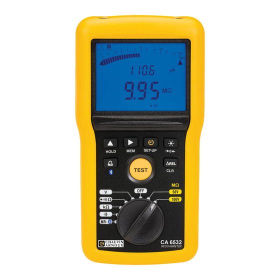
- Page 7 1.4. DESCRIPTION OF THE INSTRUMENTS 1.4.1. CA 6532 Connection terminals. Backlit digital display unit. DARPI T1T2 G VHz % < > M mAµA ALARM k nF/ km G nF µF HOLD 6 function keys. TEST TEST button to start the measurements. Ω...
- Page 8 1.4.2. CA 6534 Connection terminals. Backlit digital display unit. < > M mAµA ALARM HOLD 6 function keys. TEST TEST button to start the measurements. Ω Ω Ω 100V MR - 250V Ten-position switch to choose the function or to switch 500V the instrument off.
- Page 9 1.4.3. ON THE BACK Captive quarter-turn screw. Battery compartment cover. Magnet for attachment to a metallic surface. Non-skid pads. Prop.
- Page 10 The CA 6532 is designed for telecommunication applications (testing telephone lines). The CA 6534 is designed for applications in the electronics industry. It can also be used, with suitable probes, to test the immunity of walls and floors to electrostatic discharges (ESD).
- Page 11 1.8. FUNCTION KEYS In general, the keys have a first function, marked on the key, obtained by a short press, and a second function, marked under the key, obtained by a long press. Function The TIMER key is used to select the , PI, and DAR functions.
- Page 12 2. USE 2.1. GENERAL At start-up, the instrument indicates the remaining battery If the battery voltage is too low to ensure correct operation life. of the instrument, it so reports. G VHz The batteries must then be replaced (see § 5.2)), since the battery life indication is no longer reliable.
- Page 13 2.3. INSULATION MEASUREMENT Ω Ω 100V Set the switch to one of the MΩ positions. Ω The test voltage you should choose depends on the voltage of the installation to be tested. For example, for a network installation at 230 V, insulation measurements MR - will be made at 500 V.
- Page 14 2.3.1. OPERATION OF THE TEST BUTTON The TEST button is pressed to make an insulation measurement. The test voltage is generated for as long as the press is maintained. When the button is released, the measurement stops. In the mode, simply press the TEST button once to start the measurement, then press it a second time to stop; there is no need to keep the button pressed.
- Page 15 Interpretation of the results Condition of insulation DAR < 1,25 PI < 2 Poor or even dangerous 1,25 ≤ DAR < 1,6 2 ≤ PI < 4 Good 1,6 ≤ DAR 4 ≤ PI Excellent Press the TEST key to return to the voltage measurement. TEST 2.3.3.
- Page 16 2.4. CONTINUITY MEASUREMENT The continuity measurement measures a low resistance (< 10 or 100 Ω depending on the current) at a high current (200 or 20 mA). Press the ► key to choose current measurement. Set the switch to Ω. Ω...
- Page 17 2.4.2. ELIMINATION OF THE COMPENSATION OF THE LEADS To eliminate the compensation of the leads, leave the leads open and long-press the key. > 2s The display indicates the resistance of the leads and the symbol goes off. 2.4.3. MAKING A MEASUREMENT Use the leads to connect the device to be tested to the terminals of the instrument.
- Page 18 2.5. RESISTANCE MEASUREMENT The resistance measurement is made with a weak current and can measure resistances up to 1000 kΩ. As for a continuity measurement, connect the device to be Set the switch to kΩ. tested to the terminals of the instrument. The device to be tested must not be live (see §...
- Page 19 2.7. ΔREL FUNCTION For an insulation, resistance, or capacitance measurement, it is possible to subtract a reference value from the measured value and display the difference. To do this, make a measurement, then press the ΔREL. The main display changes to zero and the ΔREL The measurement (Rref) is stored and subtracted from symbol is displayed.
- Page 20 2.9. BACKLIGHTING Pressing the key switches on the backlighting of the display unit. To switch it off, press the key again. Otherwise, it goes off by itself at the end of one minute. 2.10. SET-UP A long press on the SET-UP key is used to enter the configuration (set-up) function of the instrument. >...
- Page 21 2.11. ALARM FUNCTION Pressing the key activates the alarm. The alarm symbol is displayed, along with the threshold, on function is available in insulation, resistance, and continuity the secondary display unit. measurements. < ALARM While it is displayed, you can change this value using the ▲ key, except during insulation measurements. For each position of the switch, there are 3 pre-recorded threshold values: ■...
- Page 22 2.12. AUTOMATIC STOP After 5 minutes of operation with no sign of the user’s presence (key press or rotation of the switch), the instrument switches to standby. Simply press any key to exit from standby. The instrument returns to the state it was in, with no loss information: value of the last measurement, compensation of the leads, ΔRel, timed mode, alarm, etc.
- Page 23 2.13.2. REREADING THE RECORDS Set the switch to MR. The instrument displays the last measurement recorded. Ω Ω 100V Ω MR - To see the other measurements, press the ▲ key. The record number is decremented and the corresponding To see one particular measurement, use the ► key to measurement is displayed.
- Page 24 Then long-press the MEM key to confirm the erasure. The record number blinks and the main display unit displays CLR. > 2s Otherwise, to cancel, long press the CLR key again. 2.13.4. ERASING ALL RECORDS Repeat the record erasure procedure: ■...
- Page 25 2.14.2. OVERSHOOT OF RANGE DURING AN INSULATION MEASUREMENT If, during an insulation measurement, the value to be measured exceeds the measurement range (which depends on the instrument and the test voltage), mAµA the instrument so reports. < In the case of a CA 6532 in the 100 V range, that leads to display of the screen shown opposite.
- Page 26 2.15. RESETTING THE INSTRUMENT If your instrument crashes, it can be reset like a PC. Then turn the switch. Press the ▲ and keys simultaneously. Ω Ω 100V Ω MR - The instrument reboots.
- Page 27 3. MEG APPLICATION SOFTWARE The MEG application software is used to: ■ configure the instrument and the measurements, ■ transfer the data recorded in the instrument to a PC. MEG can also be used to export the configuration to a file and to import a configuration file. Your PC must be equipped with a Bluetooth adapter (V2.0 or higher, supporting the SPP profile).
- Page 28 Then, in the Windows bar, locate the Bluetooth logo , right-click on it, and choose Add a peripheral. The PC searches its environment for Bluetooth-compatible devices. When the megohmmeter is detected, select it and click Next. If a coupling code is requested, enter 1111.
- Page 29 You can then transfer recorded data from the instrument to the computer. If you turn the switch to an insulation position, you can transmit the measurements in real time. To use the MEG software, refer to its help function. Each time the connection with the MEG software is lost, Bluetooth is deactivated on the instrument. Press and hold the key to reactivate it.
- Page 30 Particular reference conditions Capacitance in parallel on resistance: null Measurement ranges as a function of the model of instrument Test voltage CA 6532 CA 6534 10 V 2 kΩ - 1 GΩ 25 V 5 kΩ - 2 GΩ 50 V 10 kΩ...
- Page 31 Intrinsic uncertainty 10 V Test voltage (U Specified 1.000 - 4.00 - 40.0 - 400 - 4.00 - measurement range 999 kΩ 3.999 MΩ 39.99 MΩ 399.9 MΩ 3999 MΩ 20.00 GΩ Resolution 1 kΩ 1 kΩ 10 kΩ 100 kΩ 1 MΩ...
- Page 32 Typical test voltage vs load curve The voltage as a function of the measured resistance takes the following form: I = 1 mA / 1 mA The range of operation per IEC 61557 is from 100kΩ to 2 GΩ (see § 5.2). The maximum capacitance between the terminals is 12 µF.
- Page 33 4.2.6. CAPACITANCE MEASUREMENTS (CA 6532) ■ Capacitance Specified measurement range 0.1 - 399.9 nF 400 - 3999 nF 4.00 - 10.0 µF Resolution 0.1 nF 1 nF 10 nF Intrinsic uncertainty ± (3% + 2 ct) ■ Line length Capacitance per unit length: 40 to 60 nF/km (50 nF/km is default) Specified measurement range 0.000 - 3.999 km 4.00 - 39.99 km...
- Page 34 4.3.2. INSULATION MEASUREMENT Influence Quantities of influence Range of influence Quantity influenced Typical Maximum MΩ R ≤ 3GΩ 2%/10 °C + 2 ct 1%/10°C + 1pt 3GΩ < R < 10GΩ 3%/10 °C + 2 ct Temperature -20 to + 55 °C 10GΩ...
- Page 35 4.3.3. RESISTANCE AND CONTINUITY MEASUREMENT Influence Quantities of influence Range of influence Quantity influenced Typical Maximum at 200mA 2%/10 °C + 2 ct Temperature -20 to + 55 °C at 20mA 2%/10 °C + 2 ct 1%/10 °C + 2 ct at 200mA 4% + 2 ct Relative humidity...
- Page 36 Life between charges ■ 2,500 5-second insulation measurements at 500V with R = 500 kΩ or 6,000 at 100V with R = 100 kΩ, at the rate of one measurement per minute. ■ 3,000 5-second continuity measurements, at the rate of one measurement per minute. 4.6.
- Page 37 5. MAINTENANCE Except for the batteries, the instrument contains no parts that can be replaced by personnel who have not been specially trained and accredited. Any unauthorized repair or replacement of a part by an “equivalent” may gravely impair safety 5.1.
- Page 38 6. WARRANTY Except as otherwise stated, our warranty is valid for 24 months starting from the date on which the equipment was sold. The extract from our General Conditions of Sale is available on our website. www.group.chauvin-arnoux.com/en/general-terms-of-sale The warranty does not apply in the following cases: ■...
- Page 40 FRANCE INTERNATIONAL Chauvin Arnoux Chauvin Arnoux 12-16 rue Sarah Bernhardt Tél : +33 1 44 85 44 38 92600 Asnières-sur-Seine Fax : +33 1 46 27 95 69 Tél : +33 1 44 85 44 85 Fax : +33 1 46 27 73 89 Our international contacts info@chauvin-arnoux.com...
Need help?
Do you have a question about the CA 6534 and is the answer not in the manual?
Questions and answers