Table of Contents
Advertisement
Advertisement
Table of Contents

Summary of Contents for Eliwell Memory 1000
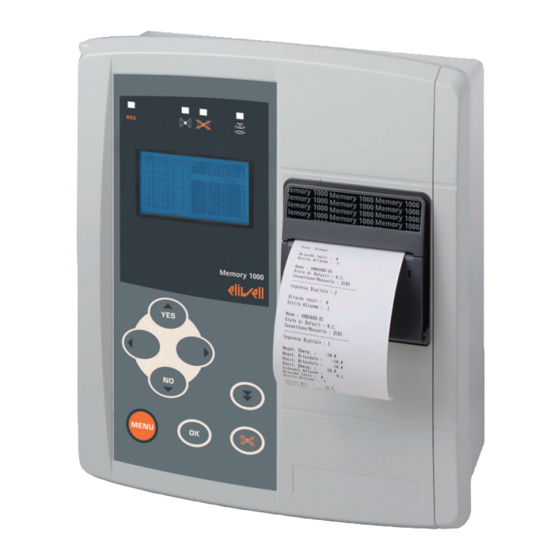
- Page 1 Memory 1000 Multichannel data logger English...
- Page 2 9MA10011 2/52...
-
Page 3: Table Of Contents
Introduction .................................. 5 User interface and menus ............................... 6 Alarms ....................................12 Standard configuration .............................. 13 Advanced configuration .............................. 22 Printer .................................... 25 Download data with SD Card............................ 32 Memory 1000 Data Manager ............................ 33 Electrical connections .............................. 36 10) Mechanical assembly ............................... 41 11) Specifications .................................. 42 12) Applicable Standards ............................... 44 13) Use ...................................... 46 14) Responsability and residual risks .......................... 46 15) Disclaimer ................................... 46 16) Annexe A – Models and Accessories .......................... 47 17) Annexe B – Eliwell Instruments ............................ 50 9MA10011 3/52... - Page 4 9MA10011 4/52...
-
Page 5: Introduction
The 12+ month data logging capacity makes Memory 1000 the ideal solution for small installations requiring HACCP data recording. Memory 1000 is a multi-channel, EN 12830 compatible data logger for recess and The graphic LCD display allows the status of the inputs to be viewed clearly and flush wall-mounting. provides access to the recorded data. Memory 1000 can manage two alarm levels for each analogue channel and can Specifications manage alarm signalling with configurable relay outputs and buzzers. • Power supply 230V a 50Hz • Up to 10 analogue/digital inputs Manual use • Relay and buzzer alarm signalling The screenshots are indicated as follows: • RS-485 port to expand inputs via compatible Eliwell Televis controllers • Graphs and tables printed on integrated printer • RS-232 port to export data using MS Windows® software (supplied) Case A • Compatible with RadioAdapter wireless networks * FIRST ACCESS * (see list of models with RS485 in “Annexe A”) Language English • Real-time measurements on the wide, backlit display • Available languages: AAAA/MM/GG: <date> - Italian, English, Spanish, German, French HH:MM:SS: <hour>... -
Page 6: User Interface And Menus
Case B 2. USER INTERFACE AND MENUS PRINTING Memory 1000 has a green LCD graphic display with backlit functions, contrast control and on/off modes configurable from parameter. The display serves as the main user interface and shows various different types Interrupted of information: • Default / main views (i.e. values of data read). • Selection menu. 2.1 Keys There are 8 keys on the front panel. Each key (see the two tables below) has: • A “direct” action (marked on the key). -
Page 7: Alarms
Description Press once Menu / Description Press once Menu / (press and release) [associated function] Comments (press and release) [associated function] Comments • in the characters See General table, it moves to Menu Only key • Opens general the label on the enabled Not enabled menu far left... - Page 8 2.2 Led and Display 2.3 Main display There are 4 icons (LED). dd/mm/yy hh:mm LEDs ONBOARD – P1 4.5 ONBOARD – P2 5.0 ONBOARD – P3 18.3 - ONBOARD – P4 20.4 - ONBOARD – P5 18.6 - ONBOARD – P6 18.4 - ONBOARD – P7 2.0 Icon Colour Permanently on Blinking ONBOARD – P8 2.3 - ONBOARD – DI Not active Data logging Jogging data ONBOARD – D2 Not active ACTIVE The Main Display on the LCD (when no keys pressed) have been: • Date and current time (dd/mm/yy and hh:mm formats respectively).
-
Page 9: Standard Configuration
2.3.1.1 Analogue inputs display * FIRST SWITCH ON * Language English All analogue inputs are shown with the following information: • Name of analogue input P1, P2,…P8**. AAAA/MM/GG: <date> - ONBOARD Px if the resource is integrated (see section 4.4 Onboard HH:MM:SS: <hour> Resources). Period REC. min : 000 - Px for Televis network resources (see section 4.5 Network 1). EN12830: <=24h / 30s • Value (2 figures with decimal point indicating tenths of a degree ) or Probe Error. • Unit of measure (C degrees centigrade; Bar pressure in bar; etc.). - Page 10 N.B.: Default values = 0 for all three passwords. EN12830 In the example, the Advanced PSW is set to 99. Obviously the 3 passwords can <=24h / 30s all be different. <=24h If you prefer, you can restrict access to menu 5 Adv. Configuration with a password. Then only an Advanced PSW holder will be allowed access to be able <=7dd to modify all three passwords. Storage > 7 dd OUTSIDE EN12380 2.4 Settings - General Menu Furthermore, if the device has onboard inputs, the following will be displayed: • The actual number of Analogue Inputs. Access to system information is organised into menus. • The actual number of Digital Inputs.
-
Page 11: Advanced Configuration
The 1 – Rec On/Off menu allows you to start or suspend data logging for I/O 2.4.7 6 - System Information resources. The menu is password-protected - see the section on how to set the Password. SYSTEM INFO NOTE: Some functions/sections in the following menus are not modifiable when Part numbers data logging is underway. The following message will appear in this case: Software version Release date dd/mm/yy Operating System Total Memory Set REC= Off Free memory To modify Menu 6 - System Information is read-only and provides general information on: IMPORTANT!: if REC = Off and if no keys have been pressed for more • Part numbers. - Page 12 From the 3.0 Active Alarms menu, you can view a list of all active alarms: 3. ALARMS • Alarm: indicates the number of the active alarm (highlighted) / total number of active alarms. In the example 001/004 (1 of 4) active alarms; the highlighted alarm is the onboard digital input 1. The 3-Alarms menu provides access to the list of alarms to view, print or reset • The list of all active alarms follows (if there are more than 4 alarms, use the UP them. and DOWN keys to see them all). • The last two lines (highlighted) show the type of resource (onboard, network) and the date (DD), hours, minutes and seconds (HH) of the start of the ALARMS highlighted alarm. Active Alarms List ------------ 3.1 Not used Print alarm log Clear log 3.2 Print alarm log 3.0 List of active Alarms 3.2 PRINT ALARMS 3.0 ACTIVE ALARMS...
- Page 13 Password-protected menu. 4. STANDARD CONFIGURATION Menu to clear (reset) the alarm log. It is highly recommended that you print the full alarm list (see 3.2) before doing this. In this way, print 3.2 will only print out the alarms that haven’t already been From the General menu, use the UP and DOWN keys to select option 5 then press printed. the OK key to open the “Standard Configuration menu. The following page will open on the display, after the correct PASSWORD has been entered**: Alarm mute To mute the alarm press the “ ” button when the device shows the main Example A: data logging underway. visualization. It is not possible to mute alarms while navigating the menu or while printing. STD CONFIGURATION - - - - - - - - - - - - - Clock & Lang Plant...
- Page 14 Language Italian CLOCK&LANGUAGE AAAA/MM/GG: <date> HH:MM:SS: <hour> AAAA/MM/GG: <data> Period REC. min : 000 HH:MM:SS : <ora> EN12830: <=24h / 30s Num. of probes used: Num. of digits used: Language Italian Reset system 0000H From this menu you can set the date, time and navigation language NOTE: unlike the first real switch on, from this menu you can also reset the system using the ‘Reset System’ field. You are advised to contact Eliwell Technical Support before doing this. 9MA10011 14/52...
-
Page 15: Printer
4.2 Plant 4.4 Onboard resources ONBOARD RESOURCES PLANT 4.4.0 General Info Name of Unit: 4.4.1 Analogue Inputs DATA LOGGER 4.4.2 Analogue Alarms REC. period min : 000 4.4.3 Digital Inputs EN12830: <=24h / 30s 4.4.4. Digital Alarms 4.4.5 Print config. From this menu you can set: • Datalogger name ‘Unit Name’: • Record period ‘REC. period’ (*) Models with no printer Note that menu 4.4.5 is not available - 000 indicates a 30-second record period. - 001 indicates a 1-minute record period. From this menu, you can - 002 indicates a 2-minute record period, and so on. • To set the number and features of Analogue and/or Digital Inputs. On changing the recording period, in real time the line below shows the • Print Analogue and Digital Input configuration (models with Printer only, see degree of conformity with UNI EN 12830 (see First Switch On). - Page 16 4.4.1 Analogue Inputs Value = 20mA 30.0 Offset This menu shows the list of onboard analogue inputs. Read 13.3 View Text 4.4.1 ANALOGUE INPUTS ONBOARD-P1 • Index: Input Index*** ONBOARD-P2 • Name: Name of Input. The default names are ONBOARD-P1 .. ONBOARD-P8 ONBOARD-P3 and can be modified as required (max. 10 characters) ONBOARD-P4 • Probe type: set automatically between [ 4…20mA and NTC 103AT] • Unit of Measure : see Units of Measure table ONBOARD-P5 • Decimal Points : values [0…3] for 4..20mA, [0…1] for NTC ONBOARD-P6 • If Probe Type = 4…20 mA : ONBOARD-P7...
- Page 17 4.4.2 Analogue alarms • Index: Input Index*** • Name: Name of Input*** This menu shows the list of onboard analogue inputs. • Alarm Output : 0=none associated; 1=Output 1; • Delay (min): minutes delay before activating Alarm Output [0…240 min] • Positiv. Emerg: upper threshold and immediate generation of alarm when 4.4.2 ANALOGUE ALARMS limit exceeded ONBOARD-P1 • Positiv. Delay: upper threshold and delayed generation of alarm when limit ONBOARD-P2 exceeded - NOTE: Positiv. Emerg. > Positiv. Delay ONBOARD-P3 • Negativ. Delay: lower threshold and delayed generation of alarm when lower ONBOARD-P4 limit exceeded ONBOARD-P5...
- Page 18 Select the required digital input using the UP and DOWN keys and press OK. 4.4.4 Digital alarms A page displaying the following information will open: This menu shows the list of onboard digital alarms. (example Index 01 Input). 4.4.2 DIGITAL ALARMS 4.4.3 DIGITAL INPUTS ONBOARD-P1 Index ONBOARD-P2 Name ONBOARD-D1 Default state NC N.C. Select the required digital input using the UP and DOWN keys and press OK. Read Open A page displaying the following information will open: (example Index 01 Input, pressure probe). View Text • Index: Input Index*** 4.4.4 DIGITAL ALARMS • Name: Name of Input. The default names are ONBOARD-D1 .. ONBOARD-D2 and can be modified as required. (number. 10 characters). Index • Default State : compressor relay. (Normally Open) or NC (Normally Closed). Name ONBOARD-D1 • Read: Real-time reading of state of input (done before reading is reversed as a Alarm Output result of previous Default State)***...
- Page 19 4.5.1 SELF-CONFIGURATION compatible Televis devices connected via RS485 to Memory 1000 can be modified from this menu. Change data Delete Network configuration NETWORK 1 4.5.0 Network Mode Network type: Televis 4.5.1 Self-configuration Last Address 4.5.2 ----------------------- First Address 4.5.3 ----------------------- 4.5.4 General Info * 4.5.5 units Automatic procedure to recognize compatible Eliwell Televis devices connected via 4.5.6 Print config. * the RS485 serial port to Memory 1000. The procedure may take a few minutes to self-configure depending on the number of devices in the network. Menu available in models with RS485 only. This menu allows you to configure ‘Network 1’ or the network of compatible Eliwell • Last address: set the value for the first address assigned to devices in the network. Televis devices connected via serial port RS485 to Memory 1000. 9MA10011 19/52...
- Page 20 • First address: set the value for the last address assigned to devices in the 4.5.5 Units network. Menu showing the List of Devices, and giving the names of Compatible Televis NOTES: Devices configured for Network 1. • Network configuration is automatic. • When adding or removing instruments from the network, repeat the self- 4.5.4 NETWORK 1 UNITS configuration procedure.
- Page 21 Total devices: (read only) 4.5.4 NETWORK 1 UNITS • Unit Index : ** ANALOGUE INPUTS • Address : ** Televis address in F:D format, resulting from the self-configuration Managed procedure. Name N1f0D1P1-- • Unit Managed : ** YES if the self-configuration process is able to read data from the device, otherwise NO. • Name (max 10 characters) View text YES testo • Alarm Output : 0=no output enabled, 1=Output 1 or 2=Output 2 • Probe info >>> Next menu (press OK) • Managed : **YES if the Televis Device makes the value available, otherwise NO.
- Page 22 5. ADVANCED CONFIGURATION 5.0 View From the General menu, use the UP and DOWN keys to select option 5 then press 5.0.0 Static text Fixed display of all analogue and digital values read. the OK key to open the “Standard Configuration” menu. The following page will You can scroll this list using the UP and DOWN keys. open on the display: 5.0.1 Rotating text Display with automatic scroll of the list of analogue NOTE: The menu is ALWAYS static; to see 5.7 and 5.8 click the DOWN key. and digital values read. ADVANCED CONFIGURATION View Alarms 5.1 Alarms Printer LCD & Buzzer ALARMS Network 1 5.1.0 Exclusion times - - - - - - - - - - - - - 5.1.1 Buzzer & Leds Network 3 5.1.2 Digital output 1 - - - - - - - - - - - - -...
- Page 23 5.1.0 EXCLUSION TIMES 5.1.2 DIGITAL OUTPUT 1 Switch on (mins) Acknowledge (mins) Enabled REC On (min) Switches off when acknowledged Off if ‘REC’ is Of • 5.1.1 BUZZER and ALARM LED functions (shown in UPPER CASE) Normally Open - Enable Buzzer (Yes/No) - Buzzer off/on during acknowledgment - Buzzer off/on if data logging is NOT active - ALARM LED on or blinking in the event of active alarms 5.2 Printer Menu visible in models with integrated printer only. 5.1.1 BUZZER & LEDS See Printer section. BUZZER 5.3 LCD & Buzzer Disabled Switches off when acknowledged Off if ‘REC’ is Of LCD & BUZZER LED IN ALARM Illuminated LCD...
- Page 24 5.6 Network 3 5.4 Network 1 Definition: Network 3 = RS232 port to download data Definition: Network 1 = RS485 to expand inputs NETWORK PARAMETERS Network type: Modbus Slave NETWORK PARAMETERS Baud Rate 19200 Time out (mS) Slave 210 address Attempts Alarm time (S) Menu available for models with RS232 only From this menu, you can set the communication network for Network 3: Network 1 & 2 To ensure the data download software runs correctly, leave the original configuration as shown in the example. Menu available for models with RS485 only From this menu, you can set the operating parameters for Network 1. 5.7 Not used See the self-configuration procedure too: • Timeout (ms) : value of the timeout for the response from controllers.
- Page 25 6. PRINTER 6.3 Printer Configuration The format for data entry is defined in Menu 5.2 Printer. See also section 5 The print function is available in models with printers only. See Annexe A. Advanced Configuration. 6.1 Keys PRINT PROPERTIES The keys to manage the integrated printer are on the bottom left of the Landscape polycarbonate panel, and are used for.
- Page 26 • Print frequency (weekly or daily). Menu 2.0 Periods displays all saved data for print preview purposes along with associated recording intervals. Start recording time (Rec On) is indicated on the left, and end recording time Print data Print (Rec Off) on the right. [Start End] interval resolution N.B.: If the device is currently recording data, the last line will have a start recording date but not an end recording date. Up to 7 recording periods are Daily Data for 1...
- Page 27 6.4.4 2.3 Print text 6.4.3 Menu 2.2 Graph Print Menu 2.3 Print Text allows you to print data for onboard/network resources as text. Same configuration as menu 2.2 (there is no Type of data to print option -see 2.2 GRAPH PRINT section 5.2 Printer). 2.2.0 Onboard resources 2.2.1 Network 1 6.5 Examples of prints 2.2.2 ------------------- N.B.: This is in reverse order compared to a real print, i.e. for Ø 30mm x57mm (integrated printer) thermal paper the print reads from the bottom to the top.
- Page 28 6.5.2 Print text example Example of graph Example of print Description DATA LOGGER Page 01 IPrint header (see graph print) 12/02/2007 Time 15:38 Device Code 0000H 004CH Daily print 12/02/2007 (1) Probe: N0-P4 (C) (2) Alarm thresholds: -10.0 10.0 (3) Emergency thresholds: -20.0 20.0 (5) Alarm acknowledged Description Data sampling for graphical print.
- Page 29 6.5.3 Example of Print Onboard Resource Configuration Example of print Description Example of print Description The print columns display (from left to right): DATA LOGGER Page 01 Print header • Reading date 12/02/2007 Time 13:56 The header appears: • Reading time Device Code 0000H 004CH • at the start of each print; (1) Reading (in the unit of Print Device • at the top of each new page. Date Time (1) (2) (3) (4) (5) measure selected for the Configuration ----------------------------------...
- Page 30 Example of print Description Example of print Description Connector/Terminal: AI01 Connector/Terminal: AI03 • Settings for Digital Inputs and Probe type: 4..20 mA Default State : N.A. Unit of Measure : Bar Name : N0-D1 • …and for Analogue Alarms Decimal Points : 1 Probe name: CONDENSING Alarm Output : • Digital alarms Min.
- Page 31 6.5.4 Example of Print Network 1 Configuration Example of print Description Print header (same as Onboard Resource) Print Configuration is organised hierarchically to make it easier to understand: • Network 1 Configuration (Type, Network Address, Units Found / Configured, Inputs Enabled, etc.) - Unit 1 Index (unit enabled YES/ NO, Analogue Inputs/Enabled), Alarms, Network Addresses, At the end the following message appears MSK/VER codes, etc.) Analogue Input 1 (Probe • End of print End of print Enabled YES/NO/UM decimal points, etc.) Analogue Input 2 •...
- Page 32 Once the controller has recognized it and checked it has been formatted, it will immediately start to download data. Data will be downloaded to this folder: Printer LED Out of paper No print Replace paper roll \\MMDATA\xxxxxxxx\BIN blinking where “xxxxxxxx” is a unique 8-figure code identifying the Memory 1000. During downloading, ‘Downloading Data’ appears on the display. Once downloading is complete, ‘SD CARD Out’ appears on the display. Printer LED Printer not No print blinking connected...
- Page 33 Insert the CDROM. The CD will start • Click “My Computer” • Click the CD (or DVD) drive (E:) automatically. Eliwell provides Memory 1000 DataManager software to enable users to access If it doesn’t where “E” is the CD/DVD drive. data recorded by Memory 1000 from a PC. The system was designed to enable • Click the Start button...
- Page 34 • Download data: to establish a connection between the PC and Memory 1000 • Graphs/Tables : to generate graphs/tables from data downloaded. 8.5 Opening screen • Historical alarm log : lists all alarms recorded by Memory 1000 in the selected period. • Control panel : configuration parameters to export data and selection of application language. Quit Minimize b) Exit program Main Functions 8.6 Barra di navigazione Plant List Download Icon Description Screen Escape starting Chart Exit program (Log-out) Table Quit Minimize Alarm History To reduce to an icon Control Panel...
- Page 35 Icon Description Screen Icon Description Screen Transfer Serial data Print Graphs Data transferred from Memory 1000 to PC Print data Tables Download Print Find Serial data Zoom Graphs Find Memory 1000 on any of the available To enlarge a portion of the graph COMs (x-axis only) Scan Zoom Graphs Tables Configuration Graphs Switch to graphic display Tables Chart Configuration Table Graphs SD Card Data download Switch to table format It allows the data download from SD card Data table X,Y values...
- Page 36 9. ELECTRICAL CONNECTIONS 8.6.2 Serial data Device name Data successfully exported 9.1 General warnings • The first time data is exported, give the Memory 1000 connected a name. IMPORTANT! • Click on transfer: data will be downloaded to the PC (this will take a few Switch off the device before working on the electrical connections. minutes).
- Page 37 Use the RS232 DB9-DB9 nullmodem cable provided or equivalent cable to Signal cables (temperature/pressure/humidity probes, digital inputs) must be connect to a PC. cabled separately from high voltage cables. Eliwell supplied cables are recommended. Contact Eliwell sales department for item availability. 9.1.3 RS485 connection RS485 Use a shielded and “twisted” , twin-conductor 0.5mm2 section cable, plus braiding (i.e. Belden cable model 8762 with PVC sleeve, 2 conductors plus...
- Page 38 9.2 Circuit diagrams The number of analogue inputs, digital inputs and alarm outputs depends on the Memory 1000 model (see section Annexe A - Models and Accessories). Modelli Base Alimentazione Modelli Standard sonde NTC Modelli Standard sonde NTC + Ingressi 4…20mA Modelli RS485 9MA10011 38/52...
- Page 39 9.2.1 Wiring diagram description Terminals Description Models Basic Standard NTC Standard NTC / 4..20mA RS485 1040 F 1045 F 1080 F 1085 F 1080 F 2AI 1085 F 2AI 1180/15F 2AI 1185/15F 2AI 1 – 2 Power Supply 230V~ Power Supply • • • •...
- Page 40 9.2.2 Connections with pressure transducers / humidity probes 4 wires / 4 fili Power Supply from / da Memory 1000 2 wires / 2 fili Power Supply from / da Memory 1000 also for / anche per IN +12 IN +12...
- Page 41 Fig. 3 10. MECHANICAL ASSEMBLY Memory 1000 was designed for wall or panel-mounting (support brackets not Hole A Hole B supplied). Remove the screw caps on the right side of the door, pressing lightly on the points indicated by the arrows in Figure 1. Take out the screws and open the door. Drill holes in the backplate at the top or bottom to pass the wires through. See the example in figure 2: Hole C Hole D...
-
Page 42: Specifications
I/O features 11. SPECIFICATIONS Type Label Description Models General specifications High voltage 1SPDT 5(2)A 250V~ Out1 All models digital relay for alarm output Standard Min. Max. outputs Supply voltage 230V~ ±10% 2 no-voltage digital Digital inputs All models inputs Supply frequency 50Hz/60Hz 5mA contact current Power draw – 2 4...20 mA current Current Memory 1080 F 2AI printer not in use Analogue inputs... - Page 43 Printer Type Label Description Models Impact thermal 6 NTC 103AT Print type printer temperature inputs10k Ω / 25°C , measurement Thermal paper Ø Models with Roll range -45 °C ÷ +105 °C; Memory 1080 F 30mm x57mm printer Analogue 1% full scale accuracy Memory 1085 F Horizontal 384pt inputs Resolution 0.1°C Memory 1080 F 2AI resolution Memory 1085 F 2AI configurable Memory 1180/15F 2AI Mechanical dimensions...
-
Page 44: Applicable Standards
12.2.1 Type of data logging Eliwell monitoring systems in the Memory 1000 family: Suitable for storage. Can be used in EN 12830-compliant applications. 12.2.2 General Requirements 12.1.1 EN12830 compatibility Measurement range • Onboard probes: -40…+ 105°C. Memory 1000 is capable of recording temperatures as per EN12830 regulation at • Network devices: Use only class II rated devices (Eliwell). the following conditions: • recording interval must be set <= 30 minutes Protection rating provided by outer casings • onboard probes must be performed with Eliwell NTC probes • IP 20. • Televis network resources must be provided with Eliwell NTC probes NOTE, FOR PRINTER ENABLE MODELS ONLY: recording of the temperatures from Supply voltage and frequency resources in the Televis network is suspended while printing. In order to guarantee... - Page 45 12.2.3 Requirements for metrological characteristics 12.2.3.1 TABLE A Maximum permissible errors, and temperature measurement resolution STANDBY TABLE FOR EACH MODEL AND FOR VARIOUS RECORDING TIMES and error • RECORDING TIME EXPRESSED IN: MINUTES. • Onboard probes: Class I -40…+ 50°C NTC INPUTS ONLY. • STAND-BY EXPRESSED IN: DAYS. • Network devices: Depends on Class II network devices. • AVERAGE NO. OF PROBES PER DEVICE: 2. STANDBY TIMES IN DAYS ARE APPROXIMATE. Recording frequency Configurable AUTO SAVE (30’’).
-
Page 46: Responsability And Residual Risks
For safety reasons, the device must be installed and used according to the instructions All possible care has been taken to ensure the accuracy of this document; provided. In particular, parts carrying dangerous voltages must not be accessible in nevertheless, Eliwell Controls srl cannot accept liability for any damage normal conditions. resulting from its use. The device must be adequately protected from water and dust according to the application, and must also only be accessible using tools (with the exception of the front panel). -
Page 47: Annexe A – Models And Accessories
16. ANNEXE A – MODELS AND ACCESSORIES 16.2 Accessories Name Part number Description NOTE 16.1 Models Paper roll Total Integrated RS485 serial Serial data Paper roll for 4..20mA Digital Paper roll Model no. of thermal to expand download RC444444 integrated inputs inputs inputs (Paper Roll) inputs printer... - Page 48 Name Part number Description NOTE Name Part number Description NOTE Pressure transducers Set the following Relative humidity parameters: EWPA 030 Set the following transducer 4...20mA parameters: EWHS300 SN520000 for 04mA=0 (measurement TD200130 0/30bar pressure for 04mA=0 for 20mA=100 range 0%...100%) See par 4.4.1 transducer with for 20mA=30 male connector See par 4.4.1 EWPA 030 EWPA 030 Set the following Humidity (range 4...20mA parameters:...
- Page 49 NOTE Wireless connectivity modules Software Tools It comes with MS Windows Memory1000 compatible data Wireless Data logging software connectivity 5555966 Radio Manager to export, save modules Adapter /S BARF0DS00NH00 and view data in RS485 or TTL table and graph / IEE802.15.4 format. converter ) Various items available. Contact Sales Department. ) Various lengths can be requested. GENERAL NOTES: • Eliwell can also supply a variety of different NTC probes depending on the cable type (PVC or silicon) and length. Wireless network RadioKey CCA0B0T01T000 configuration 9MA10011 49/52...
-
Page 50: Annexe B – Eliwell Instruments
17. ANNEXE B – ELIWELL INSTRUMENTS 17.1 Eliwell devices ID11DI0XCH700 ID 961LX NTC NTC / PTC* 230V~ ID11DL0XCH300 ID 961LX NTC BUZ. NTC / PTC* 12V~/c ID16DI0XCH300 ID 961LX NTC 16A NTC / PTC* 12V~/c ID16DI0XCH700 ID 961LX NTC 15A DI NTC / PTC* 230V~ ID23CI0XCH300 ID 974LX PTC DI PTC / NTC* 12V~/c DR35CR0SCD700 EWDR 985LX CS PTC BUZ. PTC/NTC* 230V~ ID23DI0XCH300 ID 974LX NTC NTC / PTC* 12V~/c DR35CR0SCD701 EWDR 985LX CS PTC BUZ FR PTC/NTC*... - Page 51 IC 915LX/R H/D %RH 3SCH143 M1 IWP750 IR12I00XBD300 132 23 4…20mA / 0…10V* WP35DI1XCD707 NTC / PTC* 230V~ 12V~/c 4/20mA ZANOTTI RCP3HDLX1H700 EWRC 300LX - 2Hp BUZ. 289 12 NTC / PTC* 230V~ NOTE: * configurable from parameter EWRC 300LX - 2Hp RCP3HDLX1H710 390 06 NTC / PTC* 230V~ BUZ. V2.0 EWRC 300LX - 2Hp RTC RCP3HDTX1H700 289 12 NTC / PTC* 230V~ HACCP BUZ. EWRC 300LX - 2Hp RTC RCP3HDTX1H710 390 06 NTC / PTC* 230V~ HACCP BUZ. V2.0 EWRC 500LX - 2Hp RTC RCP3UDTX0H700 289 12...
- Page 52 Eliwell Controls S.r.l. Via dell’ Industria, 15 Zona Industriale Paludi 32010 Pieve d’ Alpago (BL) Italy Telephone +39 0437 986 111 Facsimile +39 0437 989 066 Sales: +39 0437 986 100 (Italy) +39 0437 986 200 (other countries) saleseliwell@invensys.com Technical helpline: +39 0437 986 300 E-mail techsuppeliwell@invensys.com www.eliwell.it Memory 1000 2010/07/ Cod: 9MA10011 © Eliwell Controls s.r.l. 2009-2010 All rights reserved. 9MA10011 52/52...
Need help?
Do you have a question about the Memory 1000 and is the answer not in the manual?
Questions and answers