Table of Contents
Advertisement
Quick Links
Download this manual
See also:
Operating Manual
Advertisement
Table of Contents

Related Manuals for Blue-White industries FLEXFLO A-100N


Summary of Contents for Blue-White industries FLEXFLO A-100N
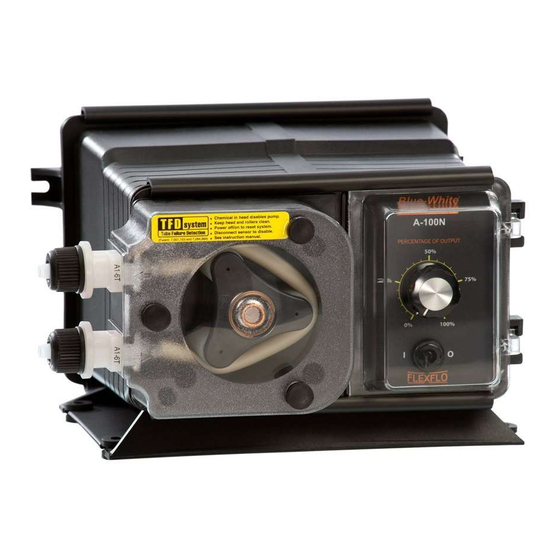
- Page 1 ® INJECTOR MODEL A-100N OPTION-E PERISTALTIC INJECTOR PUMP OPERATING MANUAL BLUE-WHITE INDUSTRIES 5300 Business Drive Huntington Beach, CA 92649 Phone: 714-893-8529 FAX: 714-894-9492 E mail: sales@blue-white.net Web site: www.blue-white.net File Name: BlueWhite_InjectorPump_A100N_E_om_D300...
-
Page 2: Table Of Contents
TABLE OF CONTENTS A-100N Page 2 SECTION HEADING PAGE Introduction Specifications A-100N Features How to install the A-100N Mounting location Electrical connections How to install the tubing and fittings How to operate the A-100N Description of Pump Output Adjustment Controls Mode Setting P1 - Manually Adjusting the output Mode Setting P2 - 4-20 mA input Mode Setting P3 - 20-4 mA input... -
Page 3: Specifications
A-100N Page 3 Specifications Maximum Working Pressure 100 psig / 6.9 bar* Maximum Fluid Temperature 130 F / 54 C Ambient Temperature Range 14 to 110 F / -10 to 43 C Enclosure NEMA 3R (acceptable for outdoor use) Duty Cycle Continuous Maximum Solids 50% by volume... -
Page 4: How To Install The A-100N
A-100N Page 4 How To Install the A-100N Note: All diagrams are strictly for guideline purposes only. Always consult an expert before installing the A-100N into specialized systems. The A-100N should be serviced by qualified persons only. Mounting Location Choose an area located near the chemical supply tank, chemical injection point and electrical supply. Although the pump is designed to withstand outdoor conditions, a cool, dry, well ventilated location is recommended. - Page 5 A-100N Page 5 TOTAL TIME INPUT ADJUST CYCLE WHEN LIT TIME INPUT DOWN STANDBY MODE PRIME 99 SEC. CYCLE RESET TUBE LIFE WARNING TIMER INPUT MODE SELECTION MENU P1 - MANUAL (INPUT OFF) P5 - 10-0VDC INVERTED P2 - 4-20mA NORMAL P6 - SLOW PULSE (X 1) P3 - 20-4mA INVERTED P7 - FAST PULSE (X 100)
-
Page 6: Electrical Connections
A-100N Page 6 Electrical Connections 4.2.1 Input Power Connections - Be certain to connect the pump to the proper supply voltage. Using the incorrect voltage will damage the pump and may result in injury. The voltage requirement is printed on the pump serial label. Note: When in doubt regarding your electrical installation, contact a licensed electrician. -
Page 7: How To Install The Tubing And Fittings
A-100N Page 7 4.2.2 External Input Signal Connections - The Model E will accept any one of four different types of external input signals. All connections are to be made inside of the junction box located on the side of the model E. A liquid-tite connector is sup- plied and should be used for the external signal cable. - Page 8 A-100N Page 8 Remove the tube nut. Push the opaque outlet (discharge) tubing onto the compression barb of the fitting. Use the tube nut to secure the tube. Hand tighten only. Outlet Tubing - (Quick-Connect models) - Locate the beige, high pressure Quick-Connect outlet fitting, see fig 6.1.
-
Page 9: How To Operate The A-100N
A-100N Page 9 How To Operate The A-100N Description of Pump Output Adjustment Controls - Open the control panel door by sliding the upper and lower slide clamps to the left. FIG. 5.2 TOTAL TIME LED - While lit, the LED digital display indicates the Total Time Setting. ON TIME LED - While lit, the LED digital display indicates the On Time Setting.. -
Page 10: Mode Setting P1 - Manually Adjusting The Output
A-100N Page 10 Mode Setting P1 - Manually adjusting the output - In this mode, the pump is turned on and off by an electronic cycle timer. The pump will energize for the duration of the “on time” and de-energize for the remainder of the “total time”... -
Page 11: Mode Setting P4 - 0-10 Vdc Input
A-100N Page 11 Mode setting P4 - 0-10VDC input - In this mode, the “total time” setting is used to set the exact number of seconds (1-99) that the pump will run when 10VDC is input; this setting is also used as the total cycle time. -
Page 12: How To Maintain The A-100N
A-100N Page 12 How to Maintain the A-100N Routine Inspection and Maintenance The A-100N requires very little maintenance. However, the pump and all accessories should be checked weekly. This is especially important when pumping chemicals. Inspect all components for signs of leaking, swelling, cracking, discoloration or corrosion. -
Page 13: How To Replace The Pump Tube
A-100N Page 13 How to Replace the Pump Tube The pump tube assembly will eventually break if not replaced. The tube has been designed for a minimum service life of 500 hours. However, the life of the tube is affected by many factors such as the type of chemical being pumped, the amount of back pressure, the motor RPM, temperature and others. -
Page 14: Replacement Parts Drawing
A-100N Page 14 Replacement Parts Drawing... -
Page 15: Replacement Parts List
A-100N Page 15... - Page 16 Blue-White Industries will not be liable for any damage that may result by the use of chemicals with their injectors and it’s components. Thank you. PROCEDURE FOR IN WARRANTY REPAIR Carefully pack the pump to be repaired, include the foot strainer and injection/check valve fitting.
Need help?
Do you have a question about the FLEXFLO A-100N and is the answer not in the manual?
Questions and answers