
Related Manuals for Blue-White industries CHEM-PRO ProSeries C3 Series


Summary of Contents for Blue-White industries CHEM-PRO ProSeries C3 Series
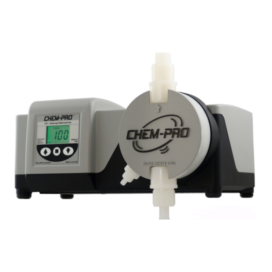
- Page 1 CHEM-PRO Diaphragm Metering Series Pumps by Blue-White Industries Series Variable Speed Positive Displacement Diaphragm Metering Pump ProSeries by Blue-White Ind. Industries, Ltd. www.Blue-White.com...
-
Page 2: Table Of Contents
Page 2 TABLE OF CONTENTS 1..Introduction ..................3 2..Specifications ...................3 3..Features ...................3 4..Unpacking ..................4 5..Installation ..................4 5.1..Mounting location ..............4 5.2..How to install the tubing and fittings. -
Page 3: Introduction
Page 3 1.0 Introduction Congratulations on purchasing the C3 Diaphragm Metering Pump. The C3 is designed to inject chemicals into piping systems and is capable of injecting against a high system pressure up to 175 PSI / 12.1 bar*. 2.0 Specifications Maximum Working Pressure* ....175 psig / 12.1 bar Maximum Fluid Temperature . -
Page 4: Unpacking
Page 4 4.0 Unpacking Your pump package should contain the following: 1 - Metering Pump 1 - 8 foot / 2.4 meter suction tube, clear PVC 1 - foot valve & strainer assembly 1 - Injection fitting with internal back-flow check valve 1 - Mounting hardware kit (two mounting brackets, 4 screws) 1 - 5 Foot / 1.5 meter Priming Tubing 5.0 Installation... - Page 5 Page 5 Typical Installation Discharge Tubing Injection / Check Valve CHEM-PRO C3V | Diaphragm Metering Pump Program MODE Minimum CHEM-PRO Maximum PRIME Blue-White Ind. IP66 Made in the USA NEMA 4X Suction Tubing Chemical Tank Priming / Degassing Tubing Foot Valve Note: All diagrams are strictly for guideline purposes only.
-
Page 6: How To Install The Tubing And Fittings
Page 6 5.2 How To Install the Tubing and Fittings CAUTION: Proper eye and skin protection must be worn when installing and servicing the pump and fittings. Suction (Inlet) Tubing Locate the inlet fitting of the pump head. Push the clear suction tubing onto the fitting barb. -
Page 7: Diaphragm Failure Detection
Made in the USA Made in the USA NEMA 4X Blue-White Industries If the DFD Alarm is triggered, the DFD and ALARM icons will begin flashing. Note: The DFD system will not reset until you have removed all traces of chemical... -
Page 8: Flow Verification System
Page 8 5.4 FVS - Flow Verification System - (sensor sold separately) The C3 is equipped with a Flow Verification System which is designed to stop the pump and provide a contact closure output in the event the sensor does not detect flow during pump operation. -
Page 9: C3F External Input/Output Signal Connection
Page 9 6.0 C3F External Input / Output Signal Connection SIGNAL INPUT/OUTPUT WIRE COLOR CODES INPUT TYPE WIRE COLOR CODE ALARM RELAY connect 2-conductor plug to either normally open (NO) (factory default) PURPLE & PURPLE or normally closed (NC) side of receptacle. 3 AMP MAX @ 125VAC (24VDC) RED/WHITE (+ 20VDC) BLACK (-) -
Page 10: How To Operate The C3F
Diaphragm the Up button Failure NEMA 4X Detection IP66 To decrease the output, press the Down button Blue-White Industries Made in the USA Increase Decrease To stop the pump, press the output speed output speed Start / Stop button Stop and... -
Page 11: C3V External Input/Output Signal Connection
Page 11 7.0 C3V External Input/Output Signal Connection C3V will accept a variety of external control input signals: 4-20mA, 0-10VDC, TTL, CMOS, AC Sine waves, contact closures, Hall Effect, NPN. The 4-20mA and 0-10 VDC loops must be powered. Two types of frequency inputs, AC sine waves (magnetic coils type outputs) and Digital Square waves (Hall Effect signals, contact closures), are acceptable. -
Page 12: How To Operate The C3V
Page 12 7.1 How To Operate The C3V Series Operation MODE Selection Button MODE button is used to Series select the mode you would MODE like to run the pump in. See CHEM-PRO below for more MODE C3V | Diaphragm Metering Pump information. -
Page 13: Operating Mode 1 - Output Adjusted Manually
Page 13 7.2 OPERATING MODE 1 - Output adjusted manually In this mode, the pump’s motor speed is adjusted manually using the front panel touch pad. The motor speed can be adjusted from 0-100%. Mode 1 Set the pump for mode 1. Press the MODE button until MODE 1 CHEM-PRO is shown on the LCD display. - Page 14 Page 14 Mode 2 Set the pump for mode 2. CHEM-PRO Press the MODE button until MODE 2 is shown on the LCD display. MODE C3V | Diaphragm Metering Pump The %SPEED or mA icon will light Program depending on the current display MODE setting.
- Page 15 Page 15 Enter the motor speed at the maximum mA input CHEM-PRO signal value. C3V | Diaphragm Metering Pump Press the DOWN button to select the digit to program. Program The digit will blink when selected. MODE Minimum Maximum Press the UP button to change the selected digit. PRIME Repeat until all digits are programmed.
-
Page 16: Operating Mode 3 - 0-10 Vdc Mode
Page 16 OPERATING MODE 3 - 0-10 VDC Mode In this mode, the pump’s motor speed is adjusted automatically based on the value of the 0-10VDC input signal. Any motor speed can be assigned to either the minimum or maximum DC input signal values. Mode 3 Set the pump for mode 3. - Page 17 Page 17 Repeat until all digits are programmed. Press the MODE button. The VDC icon will stop Program blinking and the % SPEED icon will blink. The MODE Minimum ARROW next to the word MAXIMUM will blink Maximum indicating the maximum value is ready to be programmed.
-
Page 18: Operating Mode 4 - Frequency Mode (Hz)
Page 18 Mode 3 Programming Examples, continued 100% Example 2 Output 0 VDC will result in a pump output of 10 VDC will result in a pump output of Output 0.0% VDC input from external source 100% Example 3 100% Output 0 VDC will result in a pump output of 0.0%... - Page 19 Page 19 Enter the motor speed at the minimum Hz input signal value. Press the DOWN button to select the digit to program. The digit will blink when selected. Press the UP button to change the selected digit. Repeat until all digits are programmed. Program Press the MODE button.
- Page 20 Page 20 Repeat until all digits are programmed. Press the MODE button. Programming is complete. MODE To exit the programming mode, press and hold the MODE button for more MODE than two seconds. The PROGRAM arrow will disappear. Mode 4 Programming Examples 100% Example 1 100%...
-
Page 21: Operating Mode 5 - Batch Mode
Page 21 OPERATING MODE 5 - Batch Mode In this mode, the pump’s ‘motor speed’ and ‘on time’ is configured to be initiated by a single pulse or up to 1,999 pulses. You will configure the pump in the following order: a. - Page 22 Page 22 Once all the digits are programmed, press the DOWN arrow to then select between SEC (seconds) and MIN (minutes). Use the UP arrow to scroll through SEC and MIN. Press the MODE button. The SEC or MIN icon will stop blinking and the Hz icon will blink indicating the number of pulses is ready to be programmed.
-
Page 23: Measuring The Pump's Output - Volumetric Test
Page 23 8.0 Measuring the Pump’s Output - Volumetric Test. This volumetric test will take into account individual installation factors such as line pressure, fluid viscosity, suction lift, etc. This test is the most accurate for measuring the injector’s output in an individual installation. Be sure the Injection Fitting and Footvalve / Strainer are clean and working properly. -
Page 24: How To Maintain The Pump
Page 24 9.0 How to Maintain the Pump CAUTION: Proper eye and skin protection must be worn when installing and servicing the pump. 9.1 Routine Inspection and Maintenance The pump requires very little maintenance. However, the pump and all accesso- ries should be checked regularly. -
Page 25: Pump Head And Valve Exploded View Drawing
Page 25 PUMP HEAD AND VALVE EXPLODED VIEW... -
Page 26: Replacement Parts Drawing
Page 26 Replacement Parts Drawing... -
Page 27: Replacement Parts List
Page 27 PARTS LIST Item Part No. Description Qty. 71000-583 J-Box w/ Cover 90001-157 P-Head Cover “CHEM PRO” logo 90001-158 P-Head Cover no logo 90008-035 Liquid Tight Connector (large) 90008-199 Liquid Tight Connector (small) 90011-081 Screw P-Head Cover SS 71000-584 Cover housing model C3F (Std.) 71000-585 Cover housing model C3V (Deluxe) - Page 28 Page 28 Intentionally left blank...
- Page 29 Page 29 Intentionally left blank...
-
Page 30: Warranty Information
Blue-White Industries will not be liable for any damage that may result by the use of chemicals with their injectors and it’s components. Thank you. -
Page 31: Authorized Service Centers
AUTHORIZED SERVICE CENTERS CALIFORNIA (NORTHERN) Howard E. Hutching co. (Repair Center) 7190 Penryn Plaza Penryn, CA 95663 800-568-3958 CALIFORNIA (SOUTHERN) Blue-White Industries (Repair Center) 5300 Business Drive Huntington Bch. CA 92649 714-893-8529 ILLINOIS Mullarkey Associates (Repair Center) 12346 S. Keeler Ave. - Page 32 ProSeries by Blue-White Ind. Industries, Ltd. 5300 Business Drive Huntington Beach, CA 92649 Phone: 714-893-8529 FAX: 714-894-9492 E mail: sales@blue-white.com or techsupport@blue-white.com Website: www.blue-white.com # 80000-412 Rev. 12/19/2006...
Need help?
Do you have a question about the CHEM-PRO ProSeries C3 Series and is the answer not in the manual?
Questions and answers