Table of Contents
Advertisement
Quick Links
Advertisement
Table of Contents

Related Manuals for Blue-White industries FLEXFLO M1 Series


Summary of Contents for Blue-White industries FLEXFLO M1 Series
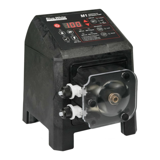
- Page 1 ® Peristaltic Metering Pump Series M1...
-
Page 2: Table Of Contents
Page 2 ® FLEXFLO M1 Introduction Available Models Engineering Specifications Materials of Construction Wetted Components Non-Wetted Components Features Agency Listings Installation Mounting Location Wall Mounting Installing Injection Fitting and Strainer Programming FVS (Flow Verification Sensor) Touchpad Layout IO Connection Programming 4-20mA Input Power Connections Output Adjustment 10.0... - Page 3 ® Page 3 FLEXFLO M1 READ THE ENTIRE OPERATING MANUAL PRIOR TO INSTALLATION AND USE. +1 (714) 893 - 8529 sales@blue-white.com customerservice@blue-white.com 5300 Business Drive Huntington Beach, CA 92649...
-
Page 4: Introduction
NOTE: The pump was pressure-tested at the factory with clean water before it was shipped, so there may be trace amounts of clean water in the pre-installed tube assembly. This is part of Blue-White Industries, Ltd.'s stringent quality assurance process. -
Page 5: Engineering Specifications
® Page 5 FLEXFLO M1 ENGINEERING SPECIFICATIONS Maximum Working Pressure (Excluding pump tubes) 100 PSI (6.89 bar) Maximum Fluid Temperature 185 F (85 C) Maximum Viscosity 5000 centipoise Maximum Suction Lift 30 ft. of water at sea level (14.7 atm psi) Ambient Operating Temperature 14 F to 115 F (-10 C to 46 C) Ambient Storage Temperature... -
Page 6: Materials Of Construction
Page 6 ® FLEXFLO M1 MATERIALS OF CONSTRUCTION Wetted Components Pump Tube Assembly ® ® ® Tubing Flex-A-Prene , Flex-A-Thane , Flex-A-Chem Adapter Fittings PVDF Non-Wetted Components ® Enclosure Valox (PBT) & PA12 ® Pump Head Valox (PBT) Polycarbonate Pump Head Cover Permanently lubricated sealed motor shaft support ball bearing. -
Page 7: Features
Heavy duty display shield protects pump controls. > Remote Start/Stop, which is one non-powered dry contact closure. > Compatible with Blue-White Industries, Ltd.’s output Flow Verification Sensor (FVS) system. > Relay outputs include a single 250V/ 3A and a single solid state. >... -
Page 8: Installation
Page 8 ® FLEXFLO M1 INSTALLATION CAUTION The pump should be serviced by qualified persons only. If equipment is used in a manner not specified in this manual, the protection provided by the equipment may be impaired. CAUTION Risk of chemical overdose. Be certain pump does not overdose chemical during backwash and periods of no flow in circulation system. -
Page 9: Wall Mounting
® Page 9 FLEXFLO M1 Wall Mounting Using the provided #10 self-tapping screws, mount the bracket to a secure wall that is located where it can be easily serviced. 4.50 in. [11.43 cm] #10 Self-Tap (2 X) Wall Mount Bracket (Side View) Mounted Pump (Front View) Lower the pump so that the tab on the wall mount is inserted into the slot located on the back of the pump. -
Page 10: Installing Injection Fitting And Strainer
Page 10 ® FLEXFLO M1 Programming FVS (Flow Verification Sensor) PERISTALTIC METERING PUMP DISPLAY % Speed Signal RUN MODES Manual MIN mA MIN % Speed Local Adjust MAX mA MAX % Speed 4-20mA Remote 1. Press & Hold mA Input to Setup Input 2. -
Page 11: Touchpad Layout
® Page 11 FLEXFLO M1 TOUCHPAD LAYOUT PERISTALTIC METERING PUMP DISPLAY % Speed Signal RUN MODES Manual MIN mA MIN % Speed Local Adjust MAX mA MAX % Speed 4-20mA Remote 1. Press & Hold mA Input to Setup Input 2. -
Page 12: Io Connection
Risk of electric shock - All wiring must be insulated and rated 60V minimum. Pump (Right Side Panel) Item Number Item USB-C Connector M12 Input Connector 1 M12 Input Connector 2 M12 Output Connector M12 connectors not included with product. Blue-White Industries requires any A-Type M12 connector with 5 position female sockets... - Page 13 ® Page 13 FLEXFLO M1 M12 Connector M12 Input Connector 1 Function Specifications Reference 120 Ohm Impedance, Non powered 4-20mA Input (+) (+) Positive loop 120 Ohm Impedance, Non powered 4-20mA Input (-) (-) Negative loop Not Used Not Used Not Used M12 Input Connector 2 Function...
-
Page 14: Programming 4-20Ma Input
Page 14 ® FLEXFLO M1 4-20mA Input CAUTION Proper eye and skin protection must be worn when installing and servicing the pump. Selecting 4-20mA input mode Directions PERISTALTIC METERING PUMP Confirm that pump is in the OFF position DISPLAY % Speed Press 4-20mA Input button Signal RUN MODES... -
Page 15: Power Connections
® Page 15 FLEXFLO M1 POWER CONNECTIONS WARNING Risk of electric shock – cord connected models are supplied with a grounding conductor and grounding-type attachment plug. To reduce risk of electric shock, be certain that it is connected only to a properly grounded, grounding-type receptacle. WARNING Electrical connections and grounding (earthing) must conform to local wiring codes. -
Page 16: Output Adjustment
Page 16 ® FLEXFLO M1 OUTPUT ADJUSTMENT The speed of the pumping mechanism is adjustable from 0.01 to 100 % motor speed (0.01 RPM to 65 RPM). 10.0 ENHANCED TUBE FAILURE DETECTION (TFD+) The pump is equipped with a Enhanced Tube Failure Detection (TFD+) system, Tubing failure which is designed to stop the pump and provide an output alarm in the event the pump tube should rupture, and a chemical enters the pump head. -
Page 17: Pump Maintenance
® Page 17 FLEXFLO M1 11.0 PUMP MAINTENANCE Always wear protective clothing, face shield, safety glasses and gloves when working on or CAUTION near your metering pump. Additional precautions should be taken depending on the solution being pumped. Refer to MSDS precautions from your solution supplier. 11.1 Routine Inspection and Maintenance The pump requires minimal maintenance. -
Page 18: Tube Replacement
Page 18 ® FLEXFLO M1 12.0 TUBE REPLACEMENT Prior to service, pump clean water through the pump and suction / discharge line to remove CAUTION any chemical. Always wear protective clothing, face shield, safety glasses and gloves when working on or CAUTION near your metering pump. - Page 19 ® Page 19 FLEXFLO M1 4. Set the motor speed to 10%. Press the Start/Stop key to start the pump. 5. With the pump running, pull the inlet (suction) fitting out of the pump head. Guide the tube counterclockwise away from the rollers. Pull the outlet (discharge)fitting out of the pump head. 6.
-
Page 20: Tube Installation
Page 20 ® FLEXFLO M1 12.3 Tube Installation NOTE: Thoroughly clean the pump head and rotor. The rotor can be removed by pulling it straight out. After cleaning, push the rotor back on the shaft. 1. Set the motor speed to 10%. Press the Start/Stop key to start the pump. 2. - Page 21 ® Page 21 FLEXFLO M1 4. Place the clear cover onto the pump head. Secure the cover with the provided three thumb screws. The pump is now ready for operation.
-
Page 22: Firmware Update
Page 22 ® FLEXFLO M1 13.0 Updating The Firmware REQUIREMENTS: Download & Install the M1 Progammer file by visiting the Firmware Update section of the M1 product page at www.blue-white.com as well as download the Firmware Update File. 1. Connect the Pump to a computer via USB-A / USB-C cable 2. - Page 23 ® Page 23 FLEXFLO M1 7. Select “.HEX” file M1-M01.hex 8. Click on “Erase-Program-Verify” 9. Once Hex file is loaded successfully 10. Click on “Disconnect”. Your firmware has now been updated.
-
Page 24: Replacement Parts List
Page 24 ® FLEXFLO M1 14.0 REPLACEMENT PARTS LIST Item Description Part Quantity Spacer, back 90011-014 Roller assembly complete (rotor) 71000-350 A1-1T, A1-3T, A1-7T Roller assembly complete (rotor) 71000-159 A1-6T Roller assembly complete (rotor) 71000-255 A1-8T ® Tube assembly, 1/4” OD tube compression, Flex-A-Thane A1-1T ®... -
Page 25: Exploded View
® Page 25 FLEXFLO M1 14.1 EXPLODED VIEW... -
Page 26: Accessories
Page 26 ® FLEXFLO M1 15.0 ACCESSORIES ® The following accessories are available for the M1 FLEXFLO Peristaltic Metering Pump. Please visit Blue- white.com for more information. All accessories are sold separately. KIT-M12 KIT-M12 WIRING INSTRUCTIONS DIAGRAM PIN # WIRE COLOR Kit contains: Two M12 PIN 1 BROWN... - Page 27 ® Page 27 FLEXFLO M1 KIT-S15 Kit contains: One 15 gallon tank, One 3/8” suction tube, One 3/8” discharge tube, One foot valve and strainer and One mounting bracket with screws KIT-S30 Kit contains: One 30 gallon tank, One 3/8” suction tube, One 3/8” discharge tube, One foot valve and strainer and One mounting bracket with screws KIT-S30 STAR III 30 GALLON TANK...
-
Page 28: Troubleshooting
Check power supply output voltage Under Voltage Check power supply output voltage Check ambient conditions, restart pump once cooled Temperature exceeds 75°C at control to ambient temperature Contact Blue-White Industries (714) 893-8529 Inverter Error customerservice@blue-white.com Contact Blue-White Industries (714) 893-8529 No Motor Connection customerservice@blue-white.com... -
Page 29: Warranty
® Page 29 FLEXFLO M1 17.0 WARRANTY 17.1 LIMITED WARRANTY Your new FLEXFLO pump is a quality product and is warrantied for 36 months from date of purchase (proof of purchase is required). The pump will be repaired or replaced at our discretion. Failure must have occurred due to defect in material or workmanship and not as a result of operation of the product other than in normal operation as defined in the pump manual. -
Page 30: Appendix A: Acronyms
Page 30 ® FLEXFLO M1 APPENDIX A: ACRONYMS Return Material Authorization °C Celsius Revolutions per minute °F Fahrenheit Steam-in-place Alternating current Solid state Unit of pressure TFD+ Enhanced Tube Failure Detection Clean-in-place TFE/P Tetrafluoroethylene propylene Centimeters Underwriters Laboratories Cash on Delivery United States Depth Volt... -
Page 31: Appendix B: Model Number Matrix
® Page 31 FLEXFLO M1 Model Number Matrix FLEXFLO ® Model Number FLEXFLO ® Peristaltic Metering Pump Power Cord (Operating voltage requirement 96VAC to 264VAC) 115V 50/60Hz, power cord NEMA 5/15 plug (US) 230V 50/60Hz, power cord NEMA 6/15 plug (US) 220V 50/60Hz, power cord CEE 7/V11 plug (EU) 240V 50/60Hz, power cord AS 3112 plug (Australia/New Zealand) 230V 50/60Hz, power cord BS 1363/A plug (United Kingdom) - Page 32 Users of electrical and electronic equipment (EEE) with the WEEE marking per Annex IV of the WEEE Directive must not dispose of end of life EEE as unsorted municipal waste, but use the collection framework available to them for the return, recycle, recovery of WEEE and minimize any potential effects of EEE on the environment and human health due to the presence of hazardous substances.
Need help?
Do you have a question about the FLEXFLO M1 Series and is the answer not in the manual?
Questions and answers