Table of Contents
Advertisement
Advertisement
Table of Contents

Related Manuals for Blue-White industries FlexFlo A-100N


Summary of Contents for Blue-White industries FlexFlo A-100N
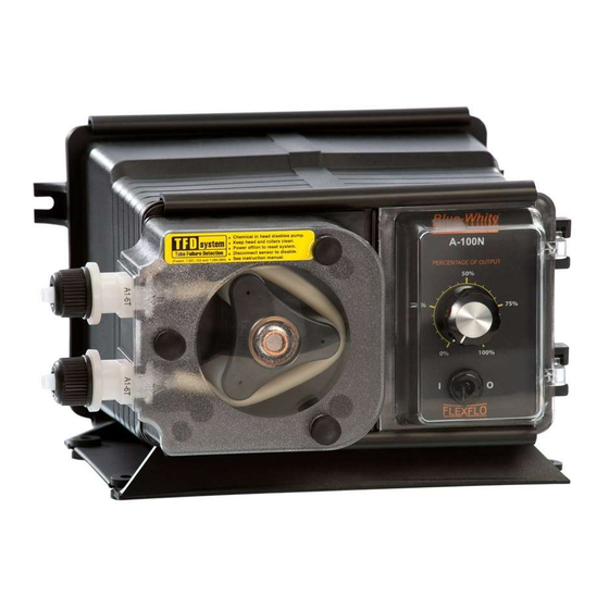
- Page 1 ® INJECTOR MODEL A-100N PERISTALTIC INJECTOR PUMP OPERATING MANUAL BLUE-WHITE INDUSTRIES 5300 Business Drive Huntington Beach, CA 92649 Phone: 714-893-8529 FAX: 714-894-9492 E mail: sales@blue-white.net Web site: www.blue-white.net File Name: BlueWhite_InjectorPump_A100N_om_D699...
-
Page 2: Table Of Contents
A-100N Page 2 TABLE OF CONTENTS SECTION HEADING PAGE Introduction Specifications A-100N Features How to install the A-100N Mounting location Electrical connections How to install the tubing and fittings How to operate the A-100N How to adjust the output -Digital Timers How to adjust the output -Fixed Timers How to adjust the output -Variable Speed Control How to maintain the A-100N... -
Page 3: Specifications
A-100N Page 3 Specifications Maximum Working Pressure 100 psig / 6.9 bar* Maximum Fluid Temperature 130 F / 54 C Ambient Temperature Range 14 to 110 F / -10 to 43 C Enclosure NEMA 3R (acceptable for outdoor use) Duty Cycle Continuous Maximum Solids 50% by volume... -
Page 4: How To Install The A-100N
A-100N Page 4 How To Install the A-100N Note: All diagrams are strictly for guideline purposes only. Always consult an expert before installing the A-100N into specialized systems. The A-100N should be serviced by qualified persons only. Mounting Location Choose an area located near the chemical supply tank, chemical injection point and electrical supply. Although the pump is designed to withstand outdoor conditions, a cool, dry, well ventilated location is recommended. - Page 5 A-100N Page 5 TOTAL TIME ADJUST CYCLE WHEN LIT TIME STANDBY DOWN PRIME 99 SEC. CYCLE RESET TUBE LIFE WARNING TIMER TOTAL TIME CYCLE TIME 1 TO 99 SECONDS ADJUSTMENT ON TIME .1 TO 99 SECONDS RECOMMEND TUBE CHANGE WHEN DISPLAY BLINKS 10 10 1.
-
Page 6: Electrical Connections
A-100N Page 6 Electrical Connections Be certain to connect the pump to the proper supply voltage. Using the incorrect voltage will damage the pump and may result in injury. The voltage requirement is printed on the pump serial label. Note: When in doubt regarding your electrical installation, contact a licensed electrician. The A-100N is supplied with either a ground wire conductor and a grounding type attachment plug (power cord) or a junction box for field wiring. - Page 7 A-100N Page 7 Cycle Adjustment Potentiometer Timer Power Board Switch Common AC/LOAD Input Ground (green) Power LOAD JB2 JB3 Jb1, Jb2, Jb3 = Voltage Selector Jumpers Neutral Jumpers Configuration Install Jb1 & Jb3, (Jb2 left open) = 115 V AC input Motor Remove all jumpers (Jb1, Jb2, &...
-
Page 8: How To Install The Tubing And Fittings
A-100N Page 8 How To Install the Tubing and Fittings 4.3.1 Inlet Tubing - (Compression tube models) -Locate the inlet fitting of the Pump Tube, see fig 6.1. Remove the tube nut. Push the clear PVC suction tubing onto the compression barb of the fitting. Use the tube nut to secure the tube. -
Page 9: How To Operate The A-100N
A-100N Page 9 4.3.4 Injection/Check Valve Fitting Installation - The Injection/Check valve fitting is designed to install directly into either 1/4” or 1/2” female pipe threads. This fitting will require periodic cleaning, espe- cially when injecting fluids that calcify such as sodium hypochlorite. These lime deposits and other build ups can clog the fitting increasing the back pressure and interfering with the check valve operation. - Page 10 A-100N Page 10 5.1.2 Digital Timer Adjustment - Open the control panel door by sliding the upper and lower slide clamps to the left. FIG. 5.1 To Adjust the Total-Time Cycle, press the up or down arrow button while the Total-Time Cycle LED indicator is lit.
-
Page 11: How To Adjust The Output -Fixed Timers
A-100N will either auto- matically begin to pump using the last speed setting, or maintain power-off status, depending on the power switch BLUE-WHITE INDUSTRIES status when the input power was disconnected. FIG. 5.2 5.3.2 Variable Speed Controller Adjustment - Slide the slide clamps to the left only far enough to open the... -
Page 12: How To Maintain The A-100N
A-100N Page 12 How to Maintain the A-100N Routine Inspection and Maintenance The A-100N requires very little maintenance. However, the pump and all accessories should be checked weekly. This is especially important when pumping chemicals. Inspect all components for signs of leaking, swelling, cracking, discoloration or corrosion. - Page 13 A-100N Page 13 6.3.1 How to Remove the Old Pump Tube The pump roller assembly spins in a counter clockwise direction. The pump head inlet (suction) side is located at the bottom of the pump and the outlet (discharge) is located at the top of the pump head. 6.3.1.1 Release any pressure that may be in the discharge Pump Head Outlet Adapter...
-
Page 14: Replacement Parts Drawing
A-100N Page 14 Replacement Parts Drawing... -
Page 15: Replacement Parts List
A-100N Page 15... - Page 16 Blue-White Industries will not be liable for any damage that may result by the use of chemicals with their injectors and it’s components. Thank you. PROCEDURE FOR IN WARRANTY REPAIR Carefully pack the pump to be repaired, include the foot strainer and injection/check valve fitting.
Need help?
Do you have a question about the FlexFlo A-100N and is the answer not in the manual?
Questions and answers