Table of Contents
Advertisement
Advertisement
Table of Contents

Subscribe to Our Youtube Channel
Related Manuals for Aruba S3500-24P


Summary of Contents for Aruba S3500-24P
- Page 1 Aruba S3500 Series Mobility Access Switch...
- Page 2 Legal Notice The use of Aruba Networks, Inc. switching platforms and software, by all individuals or corporations, to terminate other vendors’ VPN client devices constitutes complete acceptance of liability by that individual or corporation for this action and indemnifies, in full, Aruba Networks, Inc.
-
Page 3: Table Of Contents
Table or Shelf Installation ..................30 Required Tools and Equipment ..............30 Installation Steps...................30 Connecting the AC Power Cord ................30 Installing and Removing a Fan Tray ..............31 Installing and Removing a Power Supply ............32 Aruba S3500 Series Wired Access Point | Installation Guide... - Page 4 United States ..................46 Canada ....................47 Japan ......................47 Europe ....................47 Battery Statements ..................47 Proper Disposal of Aruba Equipment ..............48 Waste of Electrical and Electronic Equipment ..........48 European Union RoHS ..................48 China RoHS ....................48 Aruba S3500 Series Wired Access Point | Installation Guide...
-
Page 5: Preface
Preface This document describes the hardware features of the Aruba S3500 Series Mobility Access Switch. It provides a detailed overview of the physical and performance characteristics of each mobility access switch model and explains how to install the mobility access switch and its accessories. -
Page 6: Contacting Support
Universal Free Phone Service Number (UIFN): Australia, Canada, China, +800-4WIFI-LAN (+800-49434-526) France, Germany, Hong Kong, Ireland, Israel, Japan, Korea, Singapore, South Africa, Taiwan, and the UK All other countries +1 (408) 754-1200 | Preface Aruba S3500 Series Wired Access Point | Installation Guide... -
Page 7: S3500 Mobility Access Switch
Chapter 1 S3500 Mobility Access Switch The Aruba S3500 Mobility Access Switch is a multiport Ethernet mobility access switch that offers Layer 2 and Layer 3 switching and the capability to act as a wired access point (AP). Models The S3500 series includes four models that provide varying levels of functionality. Additionally, all models can be modified using available modules to upgrade the device’s functionality to suit your needs. -
Page 8: Front Panel
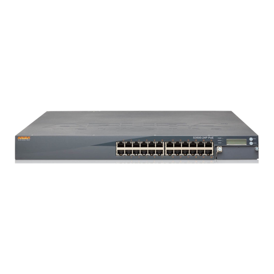
Aruba S3500 Installation Guide (Printed) End User License Agreement (Printed) Aruba Document Pointer (Printed) Optional accessories, such as SFP modules, are available for use with the Aruba S3500 Series and are sold separately. Contact your Aruba sales representative for details and assistance. Front Panel... - Page 9 Figure 1 Front Panel of the Aruba S3500 24-Port Figure 2 Front Panel of the Aruba S3500 48-Port Table 6 Front Panel Components Callout Component Description Power, Status, Stack LEDs Used for basic monitoring of the S3500 LCD Screen Used for the Quick Setup, controlling the LED behavior, and other...
-
Page 10: 10/100/1000 Ethernet Ports
Table 7 10/100/1000 Ethernet Port LEDs Function LCD Mode Indicator Status LINK/ACT Link status Green (Solid) Link has been established Green (Blinking) Activity on link No link | S3500 Mobility Access Switch Aruba S3500 Series Wired Access Point | Installation Guide... -
Page 11: Management/Status Led Indicators
Device is loading software (on initial start only) Amber (Blinking) Major Alarm Amber (Solid) Critical Alarm No power Stack Stacking indication Green (Solid) Primary Green (Blinking) Secondary Linecard (Stack Member) Aruba S3500 Series Wired Access Point | Installation Guide S3500 Mobility Access Switch |... -
Page 12: Lcd Panel
Maintenance: Allows you to execute some basic operations of the S3500 such as uploading an image or rebooting the system. Table 10 LCD Panel Mode: Boot Function/Menu Options Displays Displays boot status “Booting ArubaOS... | S3500 Mobility Access Switch Aruba S3500 Series Wired Access Point | Installation Guide... - Page 13 Uploads the mobility access switch’s current configuration to a predefined location on the attached USB flash device. Standalone: Upload Config [no | yes] Primary: Upload Config [no | yes] Non-Primary: N/A Aruba S3500 Series Wired Access Point | Installation Guide S3500 Mobility Access Switch |...
-
Page 14: Disabling The Lcd Screen
(S3500) #configure terminal (S3500) (config) #lcd (S3500) (lcd-menu) #disable menu maintenance ? factory-default media-eject quick-setup system-halt system-reboot upgrade-image upload-config (S3500) (lcd-menu) #disable menu maintenance upgrade-image ? parition0 partition1 | S3500 Mobility Access Switch Aruba S3500 Series Wired Access Point | Installation Guide... -
Page 15: Rear Panel
Rear Panel The rear panel of the Aruba S3500 mobility access switch consists of the following components: 10/100/100BASE-T Management port RJ-45 Console port USB 2.0 interface Temperature LED One Fan Tray Slot Two Power Supply Slots ... -
Page 16: Console Port
The console port is equipped with two LEDs, however these LEDs do not have a function and will not turn on. Figure 8 Serial Console Port Pin-Out Serial RJ-45 Female Console Port Pin-Out Direction Input Output | S3500 Mobility Access Switch Aruba S3500 Series Wired Access Point | Installation Guide... -
Page 17: Serial Console Port Adaptor
USB functions are controlled through the LCD panel on the front of the mobility access switch. For more information on the LCD panel and its functions, “LCD Panel” on page 12. Aruba S3500 Series Wired Access Point | Installation Guide S3500 Mobility Access Switch |... -
Page 18: Shutdown Led
Right Latch Used to secure the right side of the fan tray to the chassis. Handle Used to insert and remove the fan tray from the chassis. | S3500 Mobility Access Switch Aruba S3500 Series Wired Access Point | Installation Guide... -
Page 19: Power Supply
The Aruba S3500-series Power Supply adapts electrical power for use with the S3500. The device chassis has two slots that can hold individual power supplies to support load sharing, redundancy, and fault tolerance. -
Page 20: Hot Swapping
Power Supply Blanking Plate Covers the extra power supply slot. Do not operate your S3500 without this blanking plate or a power supply in either slot. | S3500 Mobility Access Switch Aruba S3500 Series Wired Access Point | Installation Guide... -
Page 21: Leds
The S3500-P models support PoE (802.3af) and PoE+ (802.3at) to provide power to connected devices. PoE/ PoE+ is enabled by default to provide plug and play capability for PoE capable devices. The S3500 has three PoE Management Modes: Aruba S3500 Series Wired Access Point | Installation Guide S3500 Mobility Access Switch |... -
Page 22: Poe
If interface 0/0/4 and interface 0/0/10 have the same priority but there is not enough power for both, the S3500 will eliminate 0/0/10 first. For more information on PoE and PoE management, see the ArubaOS 7.1 User Guide. | S3500 Mobility Access Switch Aruba S3500 Series Wired Access Point | Installation Guide... -
Page 23: Installation
Installation of the device should be performed by a trained installation professional. This chapter describes how to install an Aruba S3500 mobility access switch using the many mounting options available. The S3500 ships with an accessory kit that includes the equipment required to install the mobility access switch in standard, two-point 19-inch telco rack. -
Page 24: Selecting A Location
For best operation, keep the S3500 and all cords and cables at least 0.7 meters (2 feet) from fluorescent lighting fixtures, and 2 meters (6 feet) from photocopiers, radio transmitters, electric generators, and other sources of strong electromagnetic interference. | Installation Aruba S3500 Series Wired Access Point | Installation Guide... -
Page 25: Two-Point Rack Mounting
S3500. Failure to do so can result in damage to the device. Required Tools and Equipment The following tools and equipment are required for installation of an Aruba S3500 mobility access switch: Rack Mount Bracket (x2, not used for tabletop installation) ... - Page 26 S3500’s airflow requirements. 6. Leave additional space in front and back of the unit to access power cords, network cables, LCD panel, and LED status indicators | Installation Aruba S3500 Series Wired Access Point | Installation Guide...
-
Page 27: Four-Point Rack Mounting
Each S3500 should have its own mounting equipment. Do not place other networking equipment directly on top a mounted S3500. Failure to do so can result in damage to the device. The Four-Point Rack Mount kits not included in the box and is sold separately. Please contact your Aruba representative for more information. - Page 28 Figure 8. Secure the front mount brackets by inserting and tightening four (two per bracket) M6 x 15mm phillips flat head screws using a suitable Phillips Head screwdriver. | Installation Aruba S3500 Series Wired Access Point | Installation Guide...
- Page 29 12. Leave a minimum of four inches (10cm) of space on the left and right side of the unit for proper air flow and ventilation. See Figure 11 on page 19 for more information about the S3500’s airflow requirements. Aruba S3500 Series Wired Access Point | Installation Guide Installation |...
-
Page 30: Required Tools And Equipment
To turn the device off: 1. Lift the power cord retaining clip off the AC power cord. 2. Pull the AC power cord from the power supply module. | Installation Aruba S3500 Series Wired Access Point | Installation Guide... -
Page 31: Installing And Removing A Fan Tray
4. Slide the fan tray module into the mobility access switch. 5. Lift both the hinged captive screws into the lock position then secure the fan tray module by tightening the captive screws. Figure 19 Installing a Fan Tray Aruba S3500 Series Wired Access Point | Installation Guide Installation |... -
Page 32: Installing And Removing A Power Supply
Phillips Head screwdriver. Take care not to over-tighten the screw. Figure 20 Installing a Power Supply 8. Insert the power cord and secure it by lowering the power cord retaining clip over the power cord. | Installation Aruba S3500 Series Wired Access Point | Installation Guide... -
Page 33: Removing A Power Supply
6. If you are not replacing the removed power supply module, install a blanking plate that was include with your S3500 by following the installation procedure under “Installing a Power Supply” on page 32. Aruba S3500 Series Wired Access Point | Installation Guide Installation |... - Page 34 | Installation Aruba S3500 Series Wired Access Point | Installation Guide...
-
Page 35: Chapter 3 Uplink Module And Stacking
Latch Handle 10GBASE-X Port Each uplink module is equipped with four 10GBASE-X ports. These ports are intended for use with Aruba SFPs. SFPs are 10Gb hot-swappable, optical transceivers, which convert serial electrical signals to external serial optical or electrical signals. -
Page 36: 10Gbase-X Port Leds
Aruba tests and supports Aruba approved optics within their mobility access switch systems. Non-approved, third party optics are not tested or supported; therefore, Aruba does not guarantee proper functionality of non-approved, third party optics when used in an Aruba system. For a complete list of Aruba approved optics, contact your Aruba sales representative. -
Page 37: Direct Attach Cables
3m Direct Attach Cable; 10G SFP+ for stacking SFP+, Direct Attach, 5M 5m Direct Attach Cable; 10G SFP+ for stacking SFP+, Direct Attach, 7M 7m Direct Attach Cable; 10G SFP+ for stacking Aruba S3500 Series Wired Access Point | Installation Guide Uplink Module and Stacking |... -
Page 38: Installing An Uplink Module
5. Lift the left hinged captive screw and secure the uplink module by tightening both screws with a Phillips Head screwdriver. Figure 22 Uplink Module Installation | Uplink Module and Stacking Aruba S3500 Series Wired Access Point | Installation Guide... -
Page 39: Removing Uplink Module
Removing an SFP To remove an SFP module: 1. Open and release the latch on the SFP module. 2. Pull and remove the module from the port. Aruba S3500 Series Wired Access Point | Installation Guide Uplink Module and Stacking |... -
Page 40: Connecting An Lc Fiber Optic Cable
Figure 24 Connecting an LC Fiber Optic Cable M E N U E N T E P O W S T A T S T A C | Uplink Module and Stacking Aruba S3500 Series Wired Access Point | Installation Guide... -
Page 41: Installing A Direct Attach Cable
2. Pull the tab on the top of the DAC and pull the DAC out of the port (see Figure 26). Some DACs will have a rubber ring, instead of the white tab shown in Figure 26, for removal. Figure 26 DAC Removal Aruba S3500 Series Wired Access Point | Installation Guide Uplink Module and Stacking |... -
Page 42: Stacking
Mobility Access Switches, 10 Gigabit uplink ports 2 and 3 on the uplink module are pre-provisioned to be stacking ports. Once a port is provisioned for stacking, it is no longer available to be managed as a network port. A stacking port can only be connected to other Mobility Access Switches running the Aruba Stacking Protocol (ASP). -
Page 43: Creating A Stack
6. Once all the S3500s have booted up, execute the show stacking members and show stacking topology commands to view stack member assignments. Figure 27 Ring Topology Aruba S3500 Series Wired Access Point | Installation Guide Uplink Module and Stacking |... - Page 44 | Uplink Module and Stacking Aruba S3500 Series Wired Access Point | Installation Guide...
-
Page 45: Chapter 4 Specifications, Safety, And Compliance
Operating Humidity Range: 5% to 95% (RH), non-condensing Storage Specifications Storage Temperature Range: 0°C to 50°C (32°F to 122°F) Storage Humidity Range: 5% - 95% (RH), non-condensing Aruba S3500 Series Wired Access Point | Installation Guide Specifications, Safety, and Compliance |... -
Page 46: Uplink Module Specifications
Aruba products. This document can be viewed or downloaded from the following location: www.arubanetworks.com/safety_addendum Aruba wired access points must be installed by a professional installer. The professional installer is responsible for ensuring that grounding is available and it meets applicable local and national electrical codes. CLASS 1... -
Page 47: Canada
See www.dtsc.ca.gov/hazardouswaste/perchlorate for more information. Risk of explosion if battery is replaced by an incorrect type. Dispose of used batteries according to the instructions. Aruba S3500 Series Wired Access Point | Installation Guide Specifications, Safety, and Compliance |... -
Page 48: Proper Disposal Of Aruba Equipment
Proper Disposal of Aruba Equipment Waste of Electrical and Electronic Equipment Aruba products at end of life are subject to separate collection and treatment in the EU Member States, Norway, and Switzerland and therefore are marked with the symbol shown at the left (crossed-out wheelie bin). The treatment applied at end of life of these...
Need help?
Do you have a question about the S3500-24P and is the answer not in the manual?
Questions and answers