Sign In
Upload
Manuals
Brands
ADLINK Technology Manuals
Desktop
MXE-1401
ADLINK Technology MXE-1401 Manuals
Manuals and User Guides for ADLINK Technology MXE-1401. We have
1
ADLINK Technology MXE-1401 manual available for free PDF download: User Manual
ADLINK Technology MXE-1401 User Manual (100 pages)
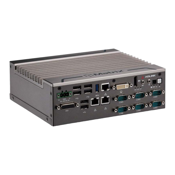
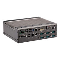
MXE-1400 Series. Fanless Embedded Computer
Brand:
ADLINK Technology
| Category:
Desktop
| Size: 5 MB
Table of Contents
Revision History
2
Preface
3
Table of Contents
5
List of Tables
9
List of Figures
11
1 Introduction
13
Overview
13
Features
14
Specifications
15
Unpacking Checklist
17
Mechanical Drawings
17
Figure 1-1: MXE-1400 Functional Block Diagram
17
Figure 1-2: Top View
18
Figure 1-3: Front View
19
Figure 1-4: Rear View
19
Figure 1-5: (Left) Side View
19
Front Panel I/O Connectors
20
Figure 1-6: Front Panel I/O
20
Table 1-1: Front Panel I/O Legend
20
LED Indicators
21
Power Button
21
Power Button Header
21
Reset Button
21
Table 1-2: LED Indicator Legend
21
Displayport Connector
22
Table 1-3: Displayport Pin Assignment
22
Multi-Display Option
23
Optional Accessories for DP to VGA/DVI Adapters
23
Audio Connector
23
Table 1-4: Multi-Display Configuration
23
DVI-I Connector
24
Table 1-5: DVI-I Connector Pin Assignment
24
Figure 1-7: Gigabit Ethernet Ports
25
Gigabit Ethernet Ports
25
COM Port Connectors
26
Figure 1-8: COM Port Connector
26
Table 1-6: Gigabit Ethernet Port LED Function
26
Cfast Port
27
Table 1-7: COM Port Pin Assignments
27
USB 2.0 Ports
27
USB 3.0 Ports
27
DB-26P Digital I/O Connector
28
DC Power Connector
28
Figure 1-9: DB-26P Digital I/O Connector
28
Table 1-8: DC Power Supply Connector Signals
28
Table 1-10: Digital I/O Specifications
29
Figure 1-10: Isolated/Differential Digital Input Circuit
30
Isolated Digital Input Circuits
30
Isolated Digital Output Circuits
30
Optional Accessories for DB-26P Digital I/O Connector
30
Figure 1-11: Isolated Digital Output Circuits
31
Figure 1-12: Isolated Digital Output Sample Application Circuit
31
Table 1-9: DB-26P Connector Pin Assignment
29
Rear Panel
32
Cfast Slot
32
HDD Fast Plug Slot
32
Table 1-11: MXE-1400 Rear Panel I/O Connector Legend
32
Figure 1-13: Rear Panel I/O
32
Internal I/O Connectors
33
Figure 1-14: Internal I/O
33
Table 1-12: Internal I/O Legend
33
Clearing CMOS Jumper
34
DC 5V and 3.3V Connectors for GPS Module
34
Figure 1-15: Clear CMOS Jumper Pin Settings
34
Table 1-13: Clear CMOS Jumper Pin Assignment
34
Figure 1-16: DC 5V and 3.3V Connectors Configuration
35
SATA Connectors
35
Table 1-14: DC 5V and 3.3V Connectors Pin Assignments
35
USIM Port
35
Extended Power/Reset/Led
36
Figure 1-17: Extended Reset/Led Configuration
36
Table 1-15: Extended Reset/Led Pin Assignments
36
2 Getting Started
37
Unpacking Checklist
37
Adaptors & Additional Accessories
37
Installing a Hard Disk Drive
37
Installing a Mini-Pcie Device
40
Installing Cfast Card
42
Connecting DC Power
43
Wall-Mounting the MXE-1400
43
Cooling Considerations
46
Driver Installation
47
A Appendix: Watchdog Timer (WDT)
49
DI/O Function Libraries
49
WDT with Api/Windows
49
Initwdt
49
Setwdt
50
DI/O with Api/Windows
52
Gpio_Init
52
Gpi_Read()
52
Gpo_Write()
53
Gpo_Read()
53
B Appendix: BIOS Setup
55
Main
56
BIOS Information
56
System Time/System Date
56
B.1 Main
56
Advanced
57
B.2 Advanced
57
CPU Configuration
58
Memory Configuration
60
Onboard Device Configuration
61
Advanced Power Management
63
Table B-1: Restore on Power Loss Settings
63
SATA Configuration
64
Serial Port Console Redirection
65
CSM Configuration
68
System Management (SEMA)
70
Chipset
71
B.3 Chipset
71
High Precision Timer
72
USB Configuration
72
Intel IGD Configuration
73
Security
74
B.4 Security
74
Boot
75
Boot Configuration
75
B.5 Boot
75
Boot Option Priorities
76
Exit
76
C Appendix: SEMA Utility GUI
79
System Overview Tab
79
Board Information
79
System Health Tab
80
Temperatures & Fan Speed
80
Power Consumption
81
Runtime Statistics
81
Flags
81
C.2.2 Power Consumption
81
User Flash Memory Tab
82
Memory
83
Write Memory
83
C.3.1 Memory
83
Hardware Control Tab
85
Watchdog
85
Backlight Control
86
Smart Fan
86
C.4.2 Backlight Control
86
Hardware Monitor Tab
88
I2C Bus Tab
89
GPIO Tab
91
C.7 GPIO Tab
91
C.7.1 GPIO Information
92
GPIO Information
92
IO Read
93
IO Write
93
IO Xorandxor
93
Status Bar
93
C.7.2 IO Read
93
Important Safety Instructions
95
Getting Service
99
Advertisement
Advertisement
Related Products
ADLINK Technology MXE-1300 Series
ADLINK Technology MXE-1301
ADLINK Technology MXE-1302
ADLINK Technology Matrix MXE-1200 Series
ADLINK Technology Matrix MXE-1212-232
ADLINK Technology Matrix MXE-1212-422
ADLINK Technology Matrix MXE-1212-485
ADLINK Technology MXE-211
ADLINK Technology MXE-5300 Series
ADLINK Technology MXE-5303
ADLINK Technology Categories
Computer Hardware
Motherboard
PCI Card
Control Unit
Desktop
More ADLINK Technology Manuals
Login
Sign In
OR
Sign in with Facebook
Sign in with Google
Upload manual
Upload from disk
Upload from URL