Sign In
Upload
Manuals
Brands
Thermo Scientific Manuals
Laboratory Equipment
5030i SHARP
Thermo Scientific 5030i SHARP Manuals
Manuals and User Guides for Thermo Scientific 5030i SHARP. We have
1
Thermo Scientific 5030i SHARP manual available for free PDF download: Instruction Manual
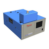
Thermo Scientific 5030i SHARP Instruction Manual (403 pages)
Synchronized Hybrid Ambient Real-time Particulate Monitor
Brand:
Thermo Scientific
| Category:
Laboratory Equipment
| Size: 3 MB
Table of Contents
Table of Contents
11
Chapter 1 Introduction
29
Principle of Operation
31
Figure 1-1. SHARP Monitor Sample Path
31
Figure 1-2. Nephelometer Sample and Zero Flow Schematic
33
Specifications
36
Table 1-1. Model 5030I Specifications
36
Installation
39
Packaging and Transport
39
Lifting
40
Unpacking and Inspection
40
Acceptance Testing and Startup Procedures
41
Figure 2-1. Remove the Packing Material
41
Acceptance Test
42
Table 2-1. Pressure Units Conversion
44
One-Point Temperature Verification
45
One-Point RH Sensor Verification
45
Figure 2-2. Model 5030I Sampling Room Air under Stable Conditions
45
One-Point Barometric Pressure Verification
46
One-Point Volumetric Flow Rate Verification
46
Leak Check Procedure
47
Nephelometer Source Verification
47
Nephelometer Zero Check
47
Setup
48
Inlet System
48
Figure 2-3. Model 5030I Side View-Inches [Millimeters]
48
Heater
49
Figure 2-4. Model 5030I Top View-Inches [Millimeters]
49
Figure 2-5. Model 5030I Vertical View
50
Sample Tube Extension Lengths
51
Rack Mounting Option
51
Monitor Installation
51
Figure 2-6. Heater Assembly
52
Figure 2-7. Rear Panel Plumbing Schematic
54
Connecting External Devices
55
Terminal Board PCB Assemblies
55
I/O Terminal Board
55
Figure 2-8. I/O Terminal Board Views
56
Table 2-2. I/O Terminal Board Pin Descriptions
56
D/O Terminal Board
57
Figure 2-9. Pin-Out of Rear Panel Connector
57
Table 2-3. Default Analog Outputs
57
Figure 2-10. D/O Terminal Board Views
58
Table 2-4. D/O Terminal Board Pin Descriptions
58
Figure 2-11. 25-Pin Terminal Board Views
59
Table 2-5. 25-Pin Terminal Board Pin Descriptions
59
Power Connections
60
Startup
60
Data Content
61
Shutdown
61
Important Tips
61
Operation
63
Display
63
Pushbuttons
64
Figure 3-1. Front Panel Display
64
Figure 3-2. Front Panel Pushbuttons
64
Soft Keys
65
Table 3-1. Front Panel Pushbuttons
65
Alphanumeric Entry Screen
66
Firmware Overview
66
Figure 3-3. Flowchart of Menu-Driven Firmware
67
Power-Up Screen
68
Run Screens
68
Ambient Conditions Run Screen
69
Mass Sensor Data Run Screen
70
Hybrid Data Run Screen
71
Main Menu
71
Range Menu
72
Concentration Units
72
Table 3-2. Standard Ranges
73
SHARP Range
73
Set Custom Ranges
74
Figure 3-4. Pin-Out of Rear Panel Connector
74
Table 3-3. Default Analog Outputs
74
Custom Ranges
75
Integration Time
75
24-Hour Average
76
24-Hour Average Start Time
76
Calibration Factors Menu
76
PM Background
77
PM Coefficient
77
SHARP Background
78
SHARP Coefficient
78
Nephelometer Background Values
78
Nephelometer Mode
79
Values
79
Restore Previous Values
79
Nephelometer Coefficient
80
Instrument Controls Menu
80
Set Flow/Pump
81
Flow
81
Pump
81
Set Heater
82
Control
82
RH Threshold
82
Temperature Threshold
83
Filter Tape Control
83
Manual
83
Mass Limit
84
Next Time
84
Period
84
Counter
85
Tape/Zero Ratio
85
Volumetric Conditions
86
Temperature Compensation
86
Standard Temperature
86
Pressure Compensation
87
Standard Pressure
87
Datalogging Settings
87
Select Srec/Lrec
88
View Logged Data
88
Number of Records
89
Date and Time
89
Erase Log
90
Select Content
90
Choose Field Data
91
Concentrations
91
Other Measurements
92
Analog Inputs
93
Figure 3-5. Common Flags
93
Figure 3-6. Detector a Flags
93
Commit Content
94
Reset to Default Content
94
Configure Datalogging
95
Logging Period Min
95
Memory Allocation Percent
95
Data Treatment
96
Flag Status Data
96
Communication Settings
97
Serial Settings
97
Baud Rate
98
Data Bits
98
Parity
98
Stop Bits
98
RS-232/RS-485 Selection
99
Instrument ID
99
Gesytec Serial Nunber
100
Communication Protocol
100
Streaming Data Configuration
100
Streaming Data Interval
101
Choose Stream Data
102
Concentrations
102
Other Measurements
102
Analog Inputs
102
TCP/IP Settings
104
Use DHCP
105
Netmask
105
Default Gateway
105
Host Name
106
Network Time Protocol Server
106
I/O Configuration
106
Output Relay Settings
106
Logic State
107
Instrument State
107
Alarms
108
Non-Alarm
108
Digital Input Settings
109
Logic State
109
Instrument Action
109
Analog Output Configuration (Select Channel)
110
Allow Over/Under Range
110
Analog Output Configuration (Select Action)
111
Select Range
111
Minimum and Maximum Value
111
Choose Signal to Output
111
Table 3-4. Analog Output Zero to Full-Scale
112
Table 3-5. Signal Type Group Choices
113
Analog Input Configuration
114
Descriptor
115
Units
115
Decimal Places
115
Number of Table Points
116
Volts
117
User Value
117
Table Points
117
Screen Contrast
118
Service Mode
118
Date/Time
119
Timezone
119
Diagnostics Menu
120
Program Versions
120
Voltages
121
Motherboard Voltages
121
Interface Board Voltages
122
I/O Board Voltages
122
Detector Board Voltages
122
Nephelometer Board Voltages
122
Rh/Temperature
123
Pressure/Vacuum
123
Flow
123
Detector Status
124
Nephelometer Status
124
Crn
124
Analog Input Readings
125
Analog Input Voltages
125
Digital Inputs
125
Relay States
126
Test Analog Outputs
126
Set Analog Outputs
127
Instrument Configuration
127
Contact Information
127
Alarms Menu
128
Instrument Alarms
128
Filter Tape Counter
129
Max Filter Tape Counter
129
Detector Alarms
129
Min and Max Alpha Alarms
130
Min and Max Beta Alarms
130
Nephelometer Alarms
130
Nephelometer Temperature
131
Nephelometer RH
132
LED Current
133
Min and Max LED Source Current Limits
133
Rh/Temperature Alarms
134
Ambient RH
134
Min and Max Ambient RH Limits
134
Sample RH
135
Ambient Temperature
136
Min and Max Ambient Temperature Limits
136
Flow Temperature
137
Min and Max Flow Temperature Limits
137
Board Temperature
137
Min and Max Board Temperature Limits
137
Pressure/Vacuum Alarms
138
Barometric Pressure
138
Vacuum
139
Flow
140
Min and Max Flow Limits
140
Flow Alarms
140
Flow
141
Min and Max Flow Limits
141
Concentration Alarms
141
Average PM
142
Average SHARP
143
Min and Max Average SHARP Concentration Limits
143
Average Nephelometer
143
Instant PM
144
Min and Max Average Nephelometer Concentration Limits
144
Instant SHARP
145
Min and Max Instant SHARP Concentration Limits
145
Instant Nephelometer
146
Service Menu
147
Rh/Temperature Calibration
147
Restore Factory Defaults
147
Chapter 4 Calibration
147
Ambient Temperature
148
Flow Temperature
148
Ambient Relative Humidity
148
Pressure/Vacuum Calibration
149
Barometer Pressure Calibration
149
Calibrate Barometer Pressure Offset
150
Calibrate Barometer Pressure Span
150
Vacuum/Flow Calibration
151
Calibrate Vacuum/Flow Offset
151
Calibrate Vacuum Pressure Span
151
Calibrate Vacuum/Flow Zero
151
Calibrate Flow Pressure Span
152
Flow Calibration
153
Auto Flow Calibration
153
Manual Flow Calibration
154
Mass Calibration
154
Mass Coefficient
154
Thermal Mass Coefficient
155
Vacuum Mass Coefficient
155
Barometer Mass Coefficient
155
Mass Coefficient
155
Auto Mass Coefficient
156
Manual Mass Coefficient
156
Alpha Efficiency Coefficient
156
Detector Calibration
157
Auto Detector Calibration
157
Manual Detector Calibration
158
Beta/Ref/Alpha Counts
158
High Voltage
158
Beta Ref Threshold
158
Alpha Threshold
159
Nephelometer Calibration
159
Nephelometer RH
160
Nephelometer Temperature
160
Nephelometer Source Level
160
Analog Output Calibration
161
Analog Input Calibration
162
Analog Output Calibrate Full-Scale
162
Analog Input Calibrate Zero
163
Analog Input Calibrate Full-Scale
163
Display Pixel Test
164
Restore User Defaults
164
Figure 4-1. Differential Pressure and Vacuum Calibration Ports
174
Flow Calibration
175
Detector Calibration
180
Chapter 5 Preventive Maintenance
184
Replacement Parts
184
Cleaning the Outside Case
184
Cleaning the Inlets
184
EPA PM Inlet
184
European PM /PM Inlet
185
Figure 5-1. U.S. EPA PM Inlet
185
Figure 5-2. European PM
186
Heater and Sample Tube
187
Weather Proofing
187
Fan Filter Inspection and Cleaning
187
Pump Rebuilding
188
Leak Test
188
Figure 5-4. Inspecting and Cleaning the Fan
188
Filter Tape Replacement
189
Greasing the Cam
190
External Pump Exhaust Filter
190
Figure 5-5. Replacing the Filter Tape
190
Figure 5-6. Replacing the External Pump Exhaust Filter
191
Cleaning the SHARP Optics Assembly
192
Chapter 6 Troubleshooting
194
Troubleshooting Guides
194
Table 6-1. Troubleshooting - General Guide
194
Table 6-2. Troubleshooting - Alarm Messages
197
Board-Level Connection Diagrams
200
Figure 6-1. Board-Level Connection Diagram - Common Electronics
200
Figure 6-2. Board-Level Connection Diagram - Measurement System
201
Connector Pin Descriptions
202
Figure 6-3. Board-Level Connection Diagram - SHARP
202
Table 6-3. Motherboard Connector Pin Descriptions
202
Table 6-4. Measurement Interface Board Connector Pin Descriptions
207
Table 6-5. Front Panel Board Connector Pin Diagram
212
Table 6-6. I/O Expansion Board (Optional) Connector Pin Descriptions
213
Table 6-7. Digital Output Board Connector Pin Descriptions
215
Table 6-8. SHARP Measurement Interface Board Pin Connections
216
Service Locations
217
Servicing
219
Safety Precautions
221
Firmware Updates
222
Accessing the Service Mode
222
Figure 7-1. Properly Grounded Antistatic Wrist Strap
222
Replacement Parts List
223
Table 7-1. Model 5030I Replacement Parts
223
Cable List
225
Table 7-2. Model 5030I Cables
225
External Device Connection Components
226
Table 7-3. External Device Connection Components
226
Figure 7-2. Model 5030I Component Layout
227
Figure 7-3. SHARP Optics Component Layout
228
Removing the SHARP Optics Assembly
229
Figure 7-4. Removing the SHARP Optics Assembly
229
Removing the Measurement Case Assembly and Lowering the Partition Panel
230
Figure 7-5. Removing the Measurement Case Assembly and Lowering the Partition Panel
230
Fuse Replacement
232
Fan/Filter Replacement
232
Detector Amplifier Assembly Replacement
233
Figure 7-6. Replacing the Fan
233
Figure 7-7. Replacing the Detector Amplifier Assembly
234
Detector Amplifier Board Calibration
235
External Pump Replacement
235
Pressure Board Replacement
236
Figure 7-8. Replacing the Pump
236
Figure 7-9. Replacing the Pressure Board Assembly
237
Pressure Board Calibration
238
Figure 7-10. Replacing the Pressure Board Assembly Plumbing Connection
238
Analog Output Testing
239
Figure 7-11. Rear Panel Analog Input and Output Pins
241
Table 7-4. Analog Output Channels and Rear Panel Pin Connections
241
Table 7-5. Analog Input Channels and Rear Panel Pin Connections
241
Analog Output Calibration
242
Analog Input Calibration
243
Calibrating the Input Channels to Zero Volts
243
Calibrating the Input Channels to Full-Scale
244
Themistor Replacement
244
I/O Expansion Board (Optional) Replacement
245
Figure 7-12. Replacing the Thermistor
245
Figure 7-13. Replacing the I/O Expansion Board (Optional)
246
Digital Output Board Replacement
247
Figure 7-14. Rear Panel Board Connectors
247
Motherboard Replacement
248
Measurement Interface Board Replacement
249
Photo Interrupt Board Replacement
250
Figure 7-15. Replacing the Measurement Interface Board
250
Proportional Valve Replacement
251
Figure 7-16. Replacing the Photo Interrupt Board
251
Detector Assembly Replacement
252
Figure 7-17. Replacing the Proportional Valve
252
Flow RTD Replacement
254
Figure 7-18. Replacing the Detector Assembly
254
Transformer Replacement
255
Figure 7-19. Replacing the RTD
255
Radius Tube Replacement
256
Figure 7-20. Replacing the Transformer
256
Ambient Rh/Temperature Replacement
257
Figure 7-21. Replacing the Radius Tube
257
Front Panel Board Replacement
259
Figure 7-22. Replacing the Ambient Rh/Temperature Assembly
259
LCD Module Replacement
260
Figure 7-23. Replacing the Front Panel Board and the LCD Module
260
Removing the SHARP Optics Cover
262
Figure 7-24. Removing the SHARP Optics Cover
262
External Solenoid Valve Replacement
263
Figure 7-25. Replacing the External Solenoid Valve
263
SHARP Rh/Temp Sensor Replacement
264
SHARP Interface Board Replacement
265
Figure 7-26. Disconnecting the Rh/Temp Connector
265
Figure 7-27. SHARP Interface Board Connections
266
Delrin Nut Replacement
267
Figure 7-28. Replacing the SHARP Optics Board
267
Figure 7-29. Replacing the Delrin Nut
268
Internal SHARP Cable Assembly Replacement
269
Case Cable Replacement
270
Figure 7-30. Replacing the Internal SHARP Cable Assembly
270
External Zeroing Filter
271
Figure 7-31. Replacing the Case Cable
271
Service Locations
272
Figure 7-32. Replacing the External Zeroing Filter
272
Chapter 8 System Description
273
Hardware
273
Figure 8-1. Model 5030I Hardware Components
274
Figure 8-2. SHARP Optics Component
275
Nephelometer Assembly
276
Primary Measurement Head
276
Detector Amplifier
276
Cam Photo Interrupt Board
276
Counter Wheel Interrupt Board Assembly
276
Proportional Valve
276
Cam Motor
276
Tape Motor
276
Pressure Board
277
External Solenoid
277
Pump Intake T-Fitting
277
Firmware
277
Instrument Control
277
Monitoring Signals
278
Output Communication
278
Electronics
278
Motherboard
278
Nephelometer Interface Board
279
Nephelometer Interface Board Connectors
279
Measurement Interface Board
279
Measurement Interface Board Connectors
280
Flow Sensor System
280
Pressure Sensor Assembly
280
Detector Amplifier Assembly
280
Digital Output Board
280
I/O Expansion Board (Optional)
281
Front Panel Connector Board
281
I/O Components
281
Analog Voltage Outputs
281
Analog Current Outputs (Optional)
282
Analog Voltage Inputs (Optional)
282
Digital Relay Outputs
282
Digital Inputs
283
Serial Ports
283
RS-232 Connection
283
Ethernet Connection
284
External Accessory Connector
284
Table 8-1. RS-232 DB9 Connector Pin Configuration
284
Table 8-2. RS-485 DB9 Connector Pin Configuration
284
RS-485 Connection
284
Optional Equipment
285
Inlet Assemblies
285
Sampling Tube Extensions
285
I/O Expansion Board Assembly
285
Pin Terminal Board Assembly
285
Terminal Block and Cable Kits
286
Cables
286
Table 9-1. Cable Options
286
Mounting Options
287
Table 9-2. Color Codes for 25-Pin and 37-Pin Cables
287
Table 9-3. Mounting Options
287
Figure 9-1. Bench Mounting
288
Figure 9-2. EIA Rack Mounting
289
Figure 9-3. Retrofit Rack Mounting
290
Figure 9-4. Rack Mount Option Assembly
291
Roof Flange Assembly
292
Figure 9-5. Roof Flange Assembly
292
Figure 9-6. Securing the Roof Flange
293
Chapter 10 Model 5014I to 5030I Upgrade Procedures
295
Instrument Preparation
295
SHARP Connection Bracket Assembly Installation
296
Figure 10-1. SHARP Optics Connection Bracket
296
Figure 10-2. Tape Pick-Up Spool Removal
297
Figure 10-3. Filter Tape Installation Pathway
298
Figure 10-4. Connecting Connection Bracket Wiring to Measurement Interface Board
299
Radius Tube Adapter Installation
299
Figure 10-5. Radius Tube Adapter Install
300
Figure 10-6. Radius Tube Adapter Alignment Check
300
SHARP External Valve Installation
301
Figure 10-7. Rear Valve Assembly Installation
301
Figure 10-8. Plumbing Diagram
302
SHARP Optics Assembly Installation
303
Figure 10-9. Optics Installation
303
Figure 10-10. Connecting the Optics to the Optics Connector
303
Upgrade of the Heater Tube Assembly
304
Figure 10-11. Upgrading 5030I Heater Assembly
304
Model Label Change
305
Power on Instrument
305
Figure 10-12. Connecting Heater to Optics Assembly Cover
305
Figure 10-13. Front Panel Label Replacement
305
Appendix A Warranty
307
Appendix B C-Link Protocol Commands
309
Instrument Identification Number
309
Commands
310
Commands List
311
Table B-1. Error Response Messages
311
Table B-2. C-Link Protocol Commands
311
Measurements
319
Figure B-1. Flags Field
320
Alarms
322
Diagnostics
331
Datalogging
335
Table B-3. Record Output Formats
339
Calibration
342
Table B-4. Stream Time Values
342
Keys/Display
352
Measurement Configuration
353
Table B-5. Standard Ranges
357
Hardware Configuration
359
Table B-6. Contrast Levels
359
Communications Configuration
362
Table B-7. Allow Mode Command Values
364
Table B-8. Reply Termination Formats
366
Table B-9. Set Layout Ack Values
367
Table B-10. Power up Mode Values
368
I/O Configuration
369
Table B-11. Analog Current Output Range Values
369
Table B-12. Analog Voltage Output Range Values
370
Table B-13. Default Analog Output Channel Assignments
371
Record Layout Definition
374
Format Specifier for ASCII Responses
374
Format Specifier for Binary Responses
374
Format Specifier for Erec Layout
375
Text
375
Value String
375
Value Source
375
Alarm Information
376
Translation Table
376
Selection Table
376
Button Designator
376
Examples
377
Appendix Cmodbus Protocol
379
Serial Communication Parameters
379
TCP Communication Parameters
380
Application Data Unit Definition
380
MBAP Header
380
Function Code
380
Data
380
Error Check
380
Function Codes
381
(0X01/0X02) Read Coils/Read Inputs
381
(0X03/0X04) Read Holding Registers/Read Input Registers
383
(0X05) Force (Write) Single Coil
385
MODBUS Parameters Supported
386
Table C-1. Read Coils for 5030I
386
Table C-2. Read Registers for 5030I
387
Table C-3. Write Coils for 5030I
389
Appendix D Gesytec (Bayern-Hessen) Protocol
392
TCP Communication Parameters
392
Instrument Address
392
Abbreviations Used
392
Basic Command Structure
392
Block Checksum Characters <BCC
393
Gesytec Commands
394
Data Sampling/Data Query Command (DA
394
Measurements Reported in Response to DA Command
397
Operating and Error Status
398
Table D-1. Operating Status for Model 5030I
398
Table D-2. Error Status for Model 5030I
398
Appendix Eesm Protocol Commands
399
ESM Commands Supported
399
Table E-1. Read Commands for 5030I
399
Table E-2. Write Commands for 5030I
400
Table E-3. Control Commands for 5030I
400
Advertisement
Advertisement
Related Products
Thermo Scientific Jewett 5030
Thermo Scientific 50131300
Thermo Scientific 50131302
Thermo Scientific 50131254
Thermo Scientific 50131317
Thermo Scientific 50131315
Thermo Scientific 50131296
Thermo Scientific 50131323
Thermo Scientific 50094596
Thermo Scientific 50093557
Thermo Scientific Categories
Laboratory Equipment
Measuring Instruments
Accessories
Freezer
Refrigerator
More Thermo Scientific Manuals
Login
Sign In
OR
Sign in with Facebook
Sign in with Google
Upload manual
Upload from disk
Upload from URL