Table of Contents
Advertisement
Quick Links
Advertisement
Table of Contents

Related Manuals for Commell FS-975M


Summary of Contents for Commell FS-975M
- Page 1 FS-975M Full-size PICMG CPU Card User’s Manual Edition 1.1 2004/08/05...
- Page 2 FS-975M User’s Manual Packing List Copyright © Copyright 2003 - 2004. All rights reserved. This document is copyrighted and all rights are reserved. The information in this document is subject to change without prior notice to make improvements to the products.
-
Page 3: Packing List
FS-975M User’s Manual Packing List Packing List Hardware: FS-975M CPU Card............Cable Kit: 40-pin UltraATA/100 IDE Cable 1 x COM / 1 x LPT Port DB9 / DB25 Cable (VL only) 2 x COM Port DB9 Cable (VL2 only) Dual-USB Port Cable with Bracket... -
Page 4: Table Of Contents
FS-975M Use’s Manual Index Index Chapter1 < Introduction > ..................7 1.1 < Product Overview >................7 1.2 < Product Specifications >................ 8 1.3 < Component Placement > ..............11 Chapter 2 < Hardware Setup >................13 2.1 < Connector location > ................13 2.2 <... - Page 5 FS-975M User’s Manual Index Appendix A < I/O Port Pin Assignment > .............. 31 A.1 < IDE Port > ................... 31 A.2 < Floppy Port > ..................32 A.3 < Parallel Port > ..................33 A.4 < Serial Ports> ..................34 A.4.1 <...
- Page 6 FS-975M Use’s Manual Index (This page is left for blank) (This page is left for blank)
-
Page 7: Chapter1 < Introduction
FS-975M User’s Manual Introduction Chapter1 < Introduction > 1.1 < Product Overview > FS-975 SBC (Single Board Computer) is an all-in-one industrial full-size PICMG (PCI/ISA)-bus CPU card based on Intel mPGA478 Pentium 4 architecture. With Intel 845 chipset, FS-975 offers the value solution with Intel NetBurst micro-architecture, 400 MHz of FSB, 3GB PC133 SDRAM, SiS315 built-in advanced 3D SVGA, and dual Intel PRO/100+ LAN and USB 1.1 I/O interfaces. -
Page 8: Product Specifications
FS-975M Use’s Manual Introduction 1.2 < Product Specifications > General Specification Form Factor Full-size PICMG-bus CPU Card / Slot PC PICMG version 1.0 (Rev. 2.0), PCI version 2.0 compliant Intel FCPGA2 Pentium 4 Processor at 400MHz FSB Intel FCPGA2 Pentium 4 processor –M at 400MHz FSB... - Page 9 FS-975M User’s Manual Introduction Solid State Disk Interface Flash Type M-systems DiskOnChip 2000, DiskOnChip Millennium, IDE Pro and DiskOnModule (DOM) solid state flash disk Package 32-pin DIP JEDEC (DiskOnChip) 40-pin IDE port (IDE Pro, DiskOnModule) Capacity 576 MB of DiskOnChip and 512 MB of DiskOnModule...
- Page 10 FS-975M Use’s Manual Introduction Power and Environment Power Req. +5V, +12V, -12V DC input from PICMG backplane Onboard 20-pin ATX power connector Additional +12V on 4-pin connector for Pentium 4 PSU ATX Function 3-pin ATX interface with 5V standby and power-on...
-
Page 11: Component Placement
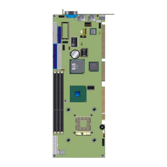
FS-975M User’s Manual Introduction 1.3 < Component Placement > Dual Intel PRO/100+ Intel ICH2 with 82562ET DiskOnChip Socket and Intel 82559ER SiS 315 4xAGP Intel 82801BA ICH2 VGA Controller With 32MB VRAM Intel 82845 MCH System Memory mPGA479 CPU Socket... - Page 12 FS-975M Use’s Manual (This page is left for blank) (This page is left for blank)
-
Page 13: Chapter 2 < Hardware Setup
FS-975M User’s Manual Hardware Setup Chapter 2 < Hardware Setup > This chapter contains the information for installation of hardware. The install procedure includes jumper settings, CPU and memory installation, fan, I/O and panel connections. 2.1 < Connector location >... -
Page 14: Jumper Reference
FS-975M Use’s Manual Hardware Setup 2.2 < Jumper Reference > Jumper Function Section JRTC COMS Operate / Clear Setting JWDT Watchdog Timer NMI / Reset Setting JDOC DiskOnChip SSD Address Setting JDOM DiskOnModule SSD Power Setting J82559 Secondary LAN Enable/Disable Setting... -
Page 15: Connector Reference
FS-975M User’s Manual Hardware Setup 2.3 < Connector Reference > Internal Onboard Connectors Connector Function Remark MicroPGA478 478 CPU Socket Standard DIMM1/2/3 168-pin DIMM Socket Standard IDE1/2 40-pin Primary / Secondary IDE Port Standard Floppy 34-pin FDD Port Standard Printer... -
Page 16: Cpu And Dram Setting
FS-975M Use’s Manual Hardware Setup 2.4 < CPU and DRAM setting > The board is based on Intel Socket 478 architecture, supports Intel mPGA478 Pentium 4 / Pentium 4 processor –M / Celeron CPU at 400 MHz FSB. The FS-975 is based on Intel 845 MCH, supports 400 MHz FSB. - Page 17 FS-975M User’s Manual Hardware Setup Unless you set the jumper and lock the processor well, the board will not work properly. Lock switch Unlock Lock Notice! Before you install the processor on the socket, please check the pin director well...
-
Page 18: Cmos Setting
FS-975M Use’s Manual Hardware Setup 2.5 < CMOS Setting > The board’s data of CMOS can be setting in BIOS. If the board refuses to boot due to inappropriate CMOS settings, here is how to proceed to clear (reset) the CMOS to its default values. -
Page 19: Watchdog Timer Setting
FS-975M User’s Manual Hardware Setup 2.6 < Watchdog Timer Setting > The watchdog timer makes the systems auto-reset while it stops to work for a period. The onboard watchdog timer can be setup as system reset or active NMI mode by jumper JWDT. -
Page 20: Embedded Solid State Disk
FS-975M Use’s Manual Hardware Setup 2.7 < Embedded Solid State Disk > The board supports both 32-pin M-systems DiskOnChip 2000 and IDE-based DiskOnChip IDE Pro and DiskOnModule (DOM) embedded flash disk. The onboard 32-pin socket, DOC, supports DiskOnChip 2000 single chip flash disk in 32-pin DIP JEDEC with jumper selectable address on jumper JDOC;... -
Page 21: Power And Fan Connectors
FS-975M User’s Manual Hardware Setup 2.8 < Power and Fan Connectors > The board provides one standard 20-pin ATX power connector and one 4-pin P4 use +12V power connector and one 3-pin ATX power-on connector. You can use this board with a backplane or simply connect it with a standard ATX power supply. - Page 22 FS-975M Use’s Manual Hardware Setup Connector: ATXR1 Type: 4-pin Standard Pentium 4 Additional +12V Power Connector Description Description Ground Ground +12V +12V Connector: JPS Type: 3-pin ATX Function Connector Description Description Description 5V Standby Ground Power On Connector: CPUFAN, SYSFAN...
-
Page 23: Display Interface
FS-975M User’s Manual Hardware Setup 2.9 < Display Interface > The board is integrated with SiS315 Graphic Controller with 256-/128-bit 3D/2D engine and 32MB physical video memory. The CRT / analog VGA interface includes one external DB15 female connector on bracket. -
Page 24: Ethernet Interface
FS-975M Use’s Manual Hardware Setup 2.10 < Ethernet Interface > The board is integrated with dual Intel PRO/100+ Fast Ethernet interfaces at the type of 10Base-T/100Base-TX auto-switching Fast Ethernet with full duplex and IEEE 802.3U compliant. Both of them connect via RJ45 connectors on bracket. The LAN2 can enable or disable by jumper J82559. -
Page 25: Serial Ports
FS-975M User’s Manual Hardware Setup 2.11 < Serial Ports > The board offers two serial ports including one RS232 COM1 and one jumper selectable RS232/422/485 COM2. The configuration of COM2 can be setting with jumper J1, J2 and JCSEL. Jumper: J1, J2, JCSEL... -
Page 26: Switch And Indicator
FS-975M Use’s Manual Hardware Setup 2.12 < Switch and Indicator > Connector: JFRNT Type: onboard 14-pin (2 x 7) 2.54-pitch header Function Signal Signal Function Vcc (+) (+) Vcc IDE LED Power Active Reset Reset Speaker Power PWRBT Button SPKIN... -
Page 27: Chapter 3 < Bios Setup
FS-975M User’s Manual BIOS Setup Chapter 3 < BIOS Setup > The single board computer uses the Award BIOS for the system configuration. The Award BIOS in the single board computer is a customized version of the industrial standard BIOS for IBM PC AT-compatible computers. It supports Intel x86 and compatible CPU architecture based processors and computers. - Page 28 FS-975M Use’s Manual (This page is left for blank) (This page is left for blank)
-
Page 29: Chapter 4 < Driver Installation
FS-975M User’s Manual Driver Installation Chapter 4 < Driver Installation > Install Chipset Software (Intel) This item will install the chipset drivers. Install VGA driver (SIS) This item will install the VGA driver to get the display properly. Install LAN driver (82562ET) This item will install the Intel 82562ET Ethernet controller driver. - Page 30 FS-975M Use’s Manual (This page is left for blank) (This page is left for blank)
-
Page 31: Appendix A < I/O Port Pin Assignment
FS-975M User’s Manual Appendix Appendix A < I/O Port Pin Assignment > A.1 < IDE Port > Connector: IDE1, IDE2 Type: 40-pin (2 x 20) box header Description Description Reset Ground Ground N/C (VCC) Ground IOW-/STOP Ground IOR-/HDMARDY Ground IORDY/DDMARDY... -
Page 32: Floppy Port
FS-975M Use’s Manual Appendix A.2 < Floppy Port > Connector: Floppy Type: 34-pin (2 x 17) header Description Description Ground DRIVE DENSITY SELECT 0 Ground DRIVE DENSITY SELECT 1 Ground Ground INDEX- Ground MOTOR ENABLE A- Ground DRIVER SELECT B-... -
Page 33: Parallel Port
FS-975M User’s Manual Appendix A.3 < Parallel Port > Connector: Printer Type: 26-pin box header Description Description STROBE- AUTO FEED- ERROR- INITIALIZE- SELECT INPUT- Ground Ground Ground Ground Ground ACKNOWLEDGE- Ground BUSY Ground PAPER EMPTY Ground SELECT+ I/O Port Pin Assignment... -
Page 34: Serial Ports
FS-975M Use’s Manual Appendix A.4 < Serial Ports> A.4.1 < Onboard RS232 Serial Ports > Connector: JCOM1, JCOM2 Type: 10-pin header Description Description Ground A.4.2 < External RS232 Serial Port > Connector: COM1 (FS-975MVL only) Type: 9-pin D-sub male connector on bracket... -
Page 35: Irda Port
FS-975M User’s Manual Appendix A.6 < IrDA Port > Connector: JIR Type: 5-pin (1 x 5) header for SIR Port Description Description CIRRX IRRX 5V Standby Ground IRTX A.7 < VGA Port > Connector: VGA Type: 15-pin D-sub female connector on bracket... -
Page 36: At Keyboard Port
FS-975M Use’s Manual Appendix A.9 < AT Keyboard Port > Connector: JATKB Type: 5-pin box header Description DATA Ground A.10 < PS/2 Keyboard and Mouse Port > Connector: PS2 Type: 6-pin MiniDIN connector on bracket Description Ground Note: The PS/2 connector supports standard PS/2 keyboard directly or both PS/2 keyboard and mouse through the PS/2 Y-type cable. -
Page 37: Appendix B < Flash Bios
FS-975M User’s Manual Appendix Appendix B < Flash BIOS > B.1 Flash Tool The board is based on Award BIOS and can be updated easily by the BIOS auto flash tool. You can download the tool online at the address below: http://www.award.com... - Page 38 FS-975M Use’s Manual (This page is left for blank) (This page is left for blank)
-
Page 39: Appendix C < System Resources
FS-975M User’s Manual Appendix Appendix C < System Resources > C.1 < I/O Port Address Map > Address Range Device x0000 - x000F Direct Access Memory Controller x0010 - x001F Motherboard Resource x0020 - x0021 Programmable Interrupt Controller x0022 - x003F... -
Page 40: System Resources
FS-975M Use’s Manual Appendix Address Range Device x03F8 - x03FF Communication Port (COM1) x0400 - x04BF Motherboard Resource x04D0 - x04D1 Motherboard Resource x0500 - x050F Intel(R) 82801BA/BAM SMBus Controller - 2443 x0778 - x077B Printer Port (LPT1) x0A78 - x0A7B... -
Page 41: Memory Address Map
FS-975M User’s Manual Appendix C.2 < Memory Address Map > Device Physical Address Length 0xA0000-0xBFFFF PCI bus x00000000 - x0009FFFF System board extension for ACPI BIOS x000A0000 - x000AFFFF SiS315 x000B0000 - x000BFFFF SiS315 x000C0000 - x000CFFFF SiS315 x000E0000 - x000EFFFF... -
Page 42: System Irq And Dma Resources
FS-975M Use’s Manual Appendix C.3 < System IRQ and DMA Resources > C.3.1 < IRQ > IRQ Number Device System Clock Standard 101/102-Key or Microsoft Natural Keyboard Programmable Interrupt Controller Communication Port (COM2) Communication Port (COM1) Intel(R) 82801BA/BAM USB Universal Host Controller - 2444... -
Page 43: Contact Information
FS-975M User’s Manual Contact Information Contact Information Any advice or comment about our products and service, or anything we can help you please don’t hesitate to contact with us. We will do our best to support you for your products, projects and business.
Need help?
Do you have a question about the FS-975M and is the answer not in the manual?
Questions and answers